1
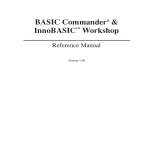
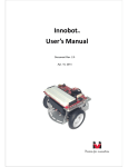
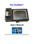
Servo Commander™ 8
User’s Guide
Document Rev 1.11
Mar. 30, 2011
Trademark
Innovati®,
, and BASIC Commander® are registered trademarks of Innovati, Inc.
™
InnoBASIC™, cmdBUS™ and Servo Commander are trademarks of Innovati, Inc.
Copyright © 2011 by Innovati, Inc. All Rights Reserved.
Due to continual product improvements, Innovati reserves the right to make modifications to its products without prior
notice. Innovati does not recommend the use of its products for application that may present a risk to human life due
to malfunction or otherwise.
No part of this publication may be reproduced or transmitted in any form or by any means without the expressed
written permission of Innovati, Inc.
Disclaimer
Full responsibility for any applications using Innovati products rests firmly with the user and as such Innovati will not be
held responsible for any damages that may occur when using Innovati products. This includes damage to equipment or
property, personal damage to life or health, damage caused by loss of profits, goodwill or otherwise. Innovati products
should not be used for any life saving applications as Innovati’s products are designed for experimental or prototyping
purposes only. Innovati is not responsible for any safety, communication or other related regulations. It is advised that
children under the age of 14 should only conduct experiments under parental or adult supervision.
Errata
We hope that our users will find this user’s guide a useful, easy to use and interesting publication, as our efforts to do
this have been considerable. Additionally, a substantial amount of effort has been put into this user’s guide to ensure
accuracy and complete and error free content, however it is almost inevitable that certain errors may have remained
undetected. As Innovati will continue to improve the accuracy of its user’s guide, any detected errors will be published
on its website. If you find any errors in the user’s guide, please contact us via email [email protected]. For the
most up-to-date information, please visit our web site at http://www.innovati.com.tw.
1
Table of Contents
Product Overview ………………………………………..………….………….……………… 3
Applications …........………………………………………….……………...………….……… 3
Product Features ….............…………………….……….........…….....….….………… 3
Product Specifications …..................…………………….………...........…………… 4
Servo and Power Connection ....…………….……….........……...….….…………… 5
Precautions for Operations .......…………….……….........……...….….…………… 6
Absolute Maximum Ratings .......…………….……….........…….....…..…………… 6
Command Set …........................….............….............….............…............. 6
Appendix A --- Tutorial Programs
Ex. 1 --- Control Servo Movement by Frames …………………………….….. 11
Ex. 2 --- Control Servo Movement by Commands …………..…..…….….. 12
2
Product Overview
Innovati’s Servo CommanderTM 8 (SC8) module incorporates the BASIC Commander® and
a ServoRunner8 module with 8 general purpose I/Os controlling up to 8 servos
simultaneously. The simple and integrated software functions enable users to directly
control the servo movement by fixed speed or common time. There are up to 60 frames
for storing the positions and motion configurations (speed or time), thus various ways of
motions can be achieved through the combinations of actions.
Note that this manual mainly describes the functionality of the servo control. For
details of the BASIC Commander® system and usage of the innoBASIC™ language, please
refer to “BASIC Commander & innoBASIC Workshop User’s Manual.”
Applications
Up to 8 Degree of Freedom RC servo applications
Up to 8 General-purpose digital I/Os applications
Up to 31 CmdBUS™ smart modules applications
Combinations of above applications
Product Features
Using the BASIC Commander® as controller, users can modify their program and
download to the Servo CommanderTM 8 board via a USB cable.
Built-in ServoRunner8 cmdBUS™ module with ID number 0.
CmdBUS™ connectors for additional Innovati’s Smart Peripheral modules.
Capable of controlling up to 8 servos for position ranging from 0.5 ms to 2.5 ms with
2μs resolution.
Software fine-tune commands in the range of -128~127 μs.
A maximum of 60 frames to store the positions, speeds or the time parameters up to
8 servos.
4 events available notifying the completion of servo travel
Module Dimensions: 40.5 mm x 50.5 mm
3
Product Specifications
Fig. 1 Servo Commander™ 8
Item
Description
1
Eight Servo Connectors numbering from 0 through 7. Please check the pin
label on the board, incorrect servo pin insertion may cause device damages.
2
6~12V Power Input: It will be regulated to 5V for the electronics on the board
and unregulated for direct servo power use. Make sure the input voltage
range is within the servo input voltage rating, otherwise the servos will be
easily damaged.
3
A cmdBUS™ connector for other Innovati’s Smart module connection.
Please check the label on board when connecting the cmdBUS cable,
incorrect insertion may damage the modules.
4
Same as item 2. May be used as power input or output pins.
5
Regulated 5V 200mA output pin and ground pin for power in your
application.
6
Eight general-purpose digital I/Os with labeled pin numbers on the board.
Through the built-in software commands, they can be used as I2C or UART
pins.
7
Red LED will be lit when power is on.
8
Yellow LED will be lit when Master/Slave is in communication.
9
Green LED will be lit when USB is in communication.
4
10
Mini USB connector: via a USB cable connecting to computer for
downloading and debugging programs.
11
RESET Button. To restart the program while the program is in
execution. Note that it is prohibited to press this button during
downloading, which will result in download failure.
Table 1 Servo Commander™ 8 Description
Servo and Power Connection
The module has 8 servo connectors with 3 pins for each connector. The servo connectors
provide power and control signals to the servos, and are placed in two groups labeled 0
through 3 and 4 through 7. To control the servos, connect the proper pins from of servo’s
connector cable to these connectors. The power supply connection is shown in Figures 2.
Before connecting the power, please check the servo operating voltage and current
ratings to avoid damages to the servos.
Fig. 2 Servo and power connection
Precautions for Operations
Please make sure of the voltage and current ranges required for the servos before connecting
them. Select a suitable power supply ranging 6V~12V and connect correctly to green terminal
block.
The Pulse pins of the servos should be connected to the module in a way complying with the
requirements shown in Table 2.
5
Symbol
Parameter
Min.
Typ.
Max.
Unit
VOH
I/O Output High Voltage
No Load
-
5
-
V
VOL
I/O Output Low Voltage
No Load
-
0
-
V
IOL
I/O Sink Current
VLOAD=0.1VOH
10
20
-
mA
IOH
I/O Source Current
VLOAD=0.9VOH
-5
-10
-
mA
INL
Operating Current
No Servo Connected
-
33
-
mA
Table 2
Test Conditions
DC Characteristics (VIN=7.5V, Ta=25°C)
Absolute Maximum Ratings
Operating Temperature of the Module: 0 °C ~ 70 °C
Storage Temperature of the Module: -50 °C ~ 125 °C
Please check servo manufacturer’s related datasheets for their servo’s absolute
maximum ratings.
Command Set
The following table lists all the unique commands provided with the ServoRunner8
Module. Note that essential words in the commands will be written in bold type and
italics in bold type. The bold type word must be written exactly as shown, whereas the
italic bold type words must be replaced with the user values. Note that the innoBASIC™
language is case-insensitive.
To execute functions related to ServoRunner8 module, please declare the module ID
number as 0 in the program, i.e. Peripheral ModuleName As ServoRunner8A @ 0
Command Syntax
Description
Servo Position Commands
SetPos (ID, Pos)
Sets the servo with ID, ranging from 0 to
7, for operation. The target position is set
by Pos ranging from 499~2500 in μs unit.
If the given value is out of this range, the
command will not be executed.
SetPosAndRun(ID, Pos)
Same as command above. Except after
settings are done, the servo will start to
move.
6
Sets the servo with ID, ranging from 0 to
7, for operation. The target position is set
by Pos ranging from 499~2500 in μs unit
SetPosSpd(ID, Pos, Spd)
and traveling at a speed of Spd ranging
0~65535 with unit μs/s. The larger the
Spd value is, the faster the servo travels.
Note that the Spd with value 0 will be
regarded as full speed.
SetPosSpdAndRun(ID, Pos, Spd)
Same as command above. Except after
settings are done, the servo will start to
move.
SetPosTime(ID, Pos, Time)
Sets the servo with ID, ranging from 0 to
7, for operation. The target position is set
by Pos ranging from 499~2500 in μs unit
and traveling to the target position in
Time ranging from 0~65535 milliseconds.
Note that if the value of Time is too short,
including 0, the servo will travel at full
speed.
SetPosTimeAndRun(ID, Pos, Time)
Same as command above. Except after
settings are done, the servo will start to
move.
Servo Start Commands
Run1Servo(ID1)
Run2Servo(ID1, ID2)
Run3Servo(ID1, …, ID3)
:
Run7Servo(ID1, …, ID7)
RunAllServo()
According to the set value of servo IDs,
ranging from 0 to 7, each corresponding
servo will perform the preset operation. If
the servo starts without the speed or
time settings but only the position
setting, the servo will travel at the
maximum speed. If any ID value is out of
its range, this command will not be
executed.
Run1ServoWithEventA(ID1)
Run2ServoWithEventA(ID1, ID2)
Run3ServoWithEventA(D1, …, ID3)
:
Run7ServoWithEventA(ID1, …, ID7)
RunAllServoWithEventA()
Same as above, except that the event A
will be triggered when all the indicated
servos reach their target positions.
7
Run1ServoWithEventB(ID1)
Run2ServoWithEventB(ID1, ID2)
Same as above, except that the event B
will be triggered when all the indicated
Run3ServoWithEventB(D1, …, ID3)
:
servos reach their target positions.
Run7ServoWithEventB(ID1, …, ID7)
RunAllServoWithEventB()
Run1ServoWithEventC(ID1)
Run2ServoWithEventC(ID1, ID2)
Same as above, except that the event C
will be triggered when all the indicated
Run3ServoWithEventC(D1, …, ID3)
:
Run7ServoWithEventC(ID1, …, ID7)
servos reach their target positions.
RunAllServoWithEventC()
Run1ServoWithEventD(ID1)
Run2ServoWithEventD(ID1, ID2)
Run3ServoWithEventD(D1, …, ID3)
:
Run7ServoWithEventD(ID1, …, ID7)
RunAllServoWithEventD()
Same as above, except that the event D
will be triggered when all the indicated
servos reach their target positions.
Servo Stop Commands
Pause1Servo(ID1)
Pause2Servo(ID1, ID2)
Pause3Servo(ID1, …, ID3)
:
Pause7Servo(ID1, …, ID7)
PauseAllServo()
According to the set value of servo IDs,
ranging from 0 to 7, each corresponding
servo will stop and hold at the present
position. If any ID value is out of its range,
this command will not be executed.
Stop1Servo(ID1)
Same as above, except that the module
Stop2Servo(ID1, ID2)
Stop3Servo(ID1, …, ID3)
:
Stop7Servo(ID1, …, ID7)
StopAllServo()
will cease sending control signal to the
servo. As a result, the servo will stop but
not hold at the present position. External
force might be able to change its position.
Servo Status and Setting Commands
Get1ServoReadyStatus(ID1, Status)
Get2ServoReadyStatus(ID1, ID2, Status)
Get3ServoReadyStatus(ID1, …, ID3, Status)
:
Get7ServoReadyStatus(ID1, …, ID7, Status)
GetAllServoReadyStatus(Status)
Gets the operation status of the servo(s)
indicated by IDs, ranging from 0 to 7, and
stores the status in Status. When all the
servos reach their target positions, the
returned status will be 1, otherwise value
0 will be returned.
8
GetNowPos (ID, Pos)
Gets the current position of the servo
indicated by ID, ranging from 0 to 7, and
then stores it in the variable Pos of type
Word. Note that the position returned is
an estimated position.
GetPos(ID, Pos)
Gets the target position of the servo
indicated by ID, ranging from 0 to 7, and
then stores it in the variable Pos of type
Word.
GetPosOffset(ID, Offset)
Gets the offset position of the servo
indicated by ID, ranging from 0 to 7, and
then stores it in the variable Offset of
type Short, ranging form -128 to 127 μs.
GetSpdAndTime(ID, Type, Value)
Gets the motion type of the servo
indicated by ID, ranging from 0 to 7, and
stores the values in Type. The
corresponding setting values are stored in
the variable Value of type Word. If the
servo travel type is set as speed, then the
returned value for Type will be 1. If the
servo travel type is set as time, then the
returned value for Type will be 0.
LoadFrame(FrameID)
Loads the servo operation settings from
the frame memory block indicated by
FrameID, ranging from 0 to 59, as the
current target position and motion type
of the servos.
LoadOffset()
Loads the servo offset settings from
EEPROM.
SaveFrame(FrameID)
Saves the current settings of servo
operations into the frame indicated by
FrameID, ranging from 0 to 59.
SaveOffset()
Saves the servo offset settings into
EEPROM.
SetPosOffset(ID, Offset)
Sets the offset of the servo indicated by
ID with the value Offset, ranging from
-128 to 127.
9
Events Name
Description
Executes the RunNServoWithEventA command, where N can be
ServoPosReadyEventA
literally 1~7 or All. When all the indicated servos reach their target
positions, event A will be triggered.
Executes the RunNServoWithEventB command, where N can be
ServoPosReadyEventB
literally 1~7 or All. When all the indicated servos reach their target
positions, event B will be triggered.
ServoPosReadyEventC
Executes the RunNServoWithEventC command, where N can be
literally 1~7 or All. When all the indicated servos reach their target
positions, event C will be triggered.
ServoPosReadyEventD
Executes the RunNServoWithEventD command, where N can be
literally 1~7 or All. When all the indicated servos reach their target
positions, event D will be triggered.
10
Appendix A --- Tutorial Programs
To help you be familiar with the Servo CommanderTM 8 module, some tutorial programs
with brief introduction are provided in this section.
To maintain the tutorial programs free of error and up-to-date, they are subject to
change without notice. For new users, who are not familiar with the BASIC Commander®,
please refer to the “BASIC Commander® and innoBASICTM Workshop User's Manual” for
more detailed information.
Ex. 1 --- Control Servo Movement by Frames
For multiple-servo applications, the related positions of each servo become abstract and
difficult to understand when designing the motion control. To solve this problem, the
frame scheme is the widely employed. This program gives the basics of servo control by
using the frames.
, The frame feature is supported on the Servo CommanderTM 8 module. The
innoBASICTM Workshop provide a software utility called “Motion Editor” which helps you
set up the positions of the servos. You can access this tool from the Tools menu in
innoBASICTM Workshop.
Assuming you have designed three frames with frame ID 0, 1 and 2. The execution
time between each movement is set to 1 second in the frame. Now let’s see how to
invoke the frame in the program. Note that the frame scheme is the easiest and fastest
way to make your multiple-servo applications work.
Peripheral mySer As ServoRunner8A @ 0
‘ Set the module ID as 0
Sub Main()
mySer.LoadFrame(0) ‘ load frame 0 data from the EEPROM on the module
mySer.RunAllServo()
‘ let all servos to execute frame 0
Pause 1000
‘ wait 1 second for servo traveling
mySer.LoadFrame(1)
mySer.RunAllServo()
Pause 1000
‘ load frame 1 data from the EEPROM on the module
‘ let all servos travel to frame 1 position
‘ wait 1 second for servo traveling
11
mySer.LoadFrame(2)
mySer.RunAllServo()
Pause 1000
‘ load frame 2 data from the EEPROM on the module
‘ let all servos to execute frame 2
‘wait 1 second for servo traveling
End Sub
The program shown above is very straight forward, which helps you understand how
the frames work intuitively. Nevertheless, you may add your own code in the program to
make it run more efficiently, more flexible motion or function combination.
Ex. 2 --- Control Servo Movement by commands
Instead of using the pre-defined movement frames, you may assign the positions of the
servos at run-time, such as the robot arm application. This program shows the usages of
the basic commands. This program might not be very meaningful in application, but it
shows you the differences among the commands in their performance.
In this example program, the position value is set according to the range of the
majority of the servos. Please adjust the allowed position range for the servos that have a
narrower travel range to avoid the damage to the servos.
Peripheral mySer As ServoRunner8A @ 0
Sub Main()
mySer.SetPosOffset(0, 30)
mySer.SetPosAndRun(0, 1500)
Pause 1000
mySer.SetPos(0, 2200)
mySer.Run1Servo(0)
Pause 1000
‘ Set the module ID as 0
‘set servo 0 mechanical offset of 30us
‘ move servo 0 to position 1500 us
‘ pause 1 second for the servo to travel
‘ set the target position of servo as 2200
‘move servo 0 to current settings
‘ pause 1 second for the servo to travel
mySer.SetPosSpdAndRun(0, 700, 1000) ‘move to position 700us, at speed 1000us/s
Pause 2000
mySer.SetPosTimeAndRun(0, 2200, 1000) ‘ move to position 2200us in 1 second
End Sub
12