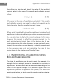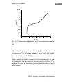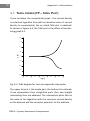
1
MOP-X1 Corrosion
Rate Meter
User Manual
Version 1.0 English, Grudzień 2012
TERCJA – Systemy Pomiarowe i Komputerowe
In case of problems
Contact the device’s producer.
TERCJA – Systemy Pomiarowe i Komputerowe
80-534 Gdańsk, ul. Starowiejska 63
Poland
tel.: +48 340 88 41
fax: +48 340 88 41
e-mail: [email protected]
website: http://www.tercja.gda.pl
Warranty
The MOP-X1 corrosion rate meter is covered by a 2 year limited
warranty from the moment of purchase. The warranty does not cover
defects resulting through fault of the user. Any signs of mechanical
damage along with internal interference will invalidate the device’s
warranty.
The TERCJA Company reserves the right to change the device’s
configuration and the programming of its products without requiring
the introduction of these changes to the already purchased products.
Any changes can be made without further information.
Disclaimer
The information contained in this manual has been thoroughly
checked and appeared to be correct at the time of the publication of
this document. TERCJA Company assumes no responsibility for any
errors that may be revealed in the future.
Copyright
Copyright 2013 by TERCJA – Measurement and Computer Systems
All rights reserved. Without the consent of the author, copyright
owner and also the publisher, no part of this publication may be
reproduced or be relayed in any form or by any means, electronic,
mechanical, photocopying, or through other means.
TERCJA – Systemy Pomiarowe i Komputerowe
TERCJA – Systemy Pomiarowe i Komputerowe
5
MOP-X1 User Manual
TABLE OF CONTENTS
1
Introduction ..........................................................................7
2
Technical specification ..........................................................9
3
Meter functions...................................................................11
4
Package contents.................................................................13
5
Measurement sensors.........................................................15
5.1
Dedicated sensor .........................................................17
5.2
Custom sensor .............................................................18
6
Front panel ..........................................................................21
7
Connector ............................................................................23
7.1
8
Preparation for use .............................................................25
8.1
9
Connecting your own sensors .....................................23
Battery replacement ...................................................26
Measurement ......................................................................27
10 User menu ...........................................................................31
10.1 Meter options..............................................................31
10.1.1
Date and time ......................................................31
10.1.2
Automatic shutoff ................................................31
10.1.3
Setting the dispaly and sound..............................32
10.1.4
Resetting to default values ..................................33
10.2 Measurement options .................................................33
10.2.1
Measurement units..............................................34
10.2.2
Automatic measure mode ...................................34
10.2.3
Sensor settings .....................................................35
10.2.4
Environment resistance .......................................38
10.2.5
Electrode order ....................................................38
TERCJA – Systemy Pomiarowe i Komputerowe
6
Table of contents
10.2.6
Calibration ........................................................... 40
10.3 Reading measurements results .................................. 41
11 Measurement results ......................................................... 43
12 Method for calculating corrosion rate ............................... 47
13 Additional adapters ............................................................ 53
13.1 MOP-X1-US ................................................................. 53
13.2 MOP-X1-USB ............................................................... 54
14 References .......................................................................... 55
15 Appendix A – Basics of a method ....................................... 57
TERCJA – Systemy Pomiarowe i Komputerowe
7
MOP-X1 User Manual
1 INTRODUCTION
Thank you for your interest in our product. A corrosion rate
meter is used to determine the rate at which material diminishes due to corrosion, which is inevitable. The results are given in very simple units of mm / year. This allows you to estimate the life expectancy of an existing installation. The measurement is instantaneous and reflects the corrosion rate at the
moment of measurement. As a result, it is possible to test the
performance of applied corrosion protection e.g. inhibitors.
The meter operates on the generally accepted method of linear polarization (LPR - Linear Polarization Resistance) and is
used in conductive environments. It can be used in assessing
the corrosion rate of all water pipes made of various metals
such as structural steel, stainless steel, brass, copper etc.
Should you require the measurement of corrosion rate in nonconductive media such as liquid hydrocarbons or gases we
invite you to examine our other products – electrical resistance meter to measure corrosion rate. It also operates on a
generally accepted principle – electrical resistance method.
The meters can also be produced in a stationary version and,
together with sensors, possess the appropriate certificates
allowing operation in explosion hazard areas.
TERCJA – Systemy Pomiarowe i Komputerowe
8
Introduction
TERCJA – Systemy Pomiarowe i Komputerowe
9
MOP-X1 User Manual
2 TECHNICAL SPECIFICATION
Power
4 ‘AA’ Batteries
Operating time on fully-charged batteries:
Up to 400 hours*
Standby time
Approximately 1 year
Power consumption in standby mode:
0.1 mA
Power consumption in active mode:
4 mA
Power consumption during test:
6 mA
Backlight power consumption
6 mA
Clock backup time
3 minutes
Dimensions (length X width X height)
185 x 80 x 45 mm
Weight (without batteries)
570 g
Degree of Protection
IP67
Display
Monochromatic
Display 128x64
Signal
Sound
* when backlight is deactivated
TERCJA – Systemy Pomiarowe i Komputerowe
10
Technical specification
TERCJA – Systemy Pomiarowe i Komputerowe
11
MOP-X1 User Manual
3 METER FUNCTIONS
The MOP-X1 corrosion rate meter contains the following functions:
- Corrosion rate measurement using the linear polarization
method
- Display of measurement results in mm/year (mmpy) or
mils/year (mpy)
- Temperature measurement if the sensor is equipped with
this feature.
- Measurement of the quality assessment algorithm (scale 0100) based on multiple parameters, such as the potential
difference between the electrodes, voltage and current
fluctuations, and the exceeding of ranges, etc.
- Automatic signaling for suspected pitting corrosion, and
also for damage or measurement sensor wear.
- Automatic connection with the measurement sensor and
collect from it, data with respect to the test material, geometrical properties and the properties of the corrosive environment.
- The ability to change the functions of the individual electrodes in the measurement sensor, and thus executing
three independent measurements with one sensor.
- The ability to connect your own corrosion sensors and set
up data with respect to the test material, geometrical
properties, and the properties of the corrosive environment.
(OPTIONAL – using an MOP-X1-US adapter)
TERCJA – Systemy Pomiarowe i Komputerowe
12
Meter functions
- The ability of quick measurements with your own sensors,
using the empirical relationship for structural steel and
brass.
(OPTIONAL – using an MOP-X1-US adapter)
- The ability to save up to 100 results in the device’s memory
along with a description and allowing their later reading.
- The ability to record the results to a computer, export them
to a text file, and analyze them in MOPCorr dedicated
software.
(OPTIONAL – using an MOP-X1-USB adapter)
TERCJA – Systemy Pomiarowe i Komputerowe
13
MOP-X1 User Manual
4 PACKAGE CONTENTS
The basic set consists of:
-
MOP-X1 corrosion rate sensor
Calibration tip
4 X NiMH 2200mAh batteries
Battery charger
4 mm Allen key
Instruction Manual
Carrying case for the device
Optional items in the set include:
- MOP-X1-USB Adapter
Allows for connection of the meter to a computer
- MOP-X1-US Adapter
Allows for the use of your own corrosion sensors.
TERCJA – Systemy Pomiarowe i Komputerowe
14
Package contents
TERCJA – Systemy Pomiarowe i Komputerowe
15
MOP-X1 User Manual
5 MEASUREMENT SENSORS
Apart from just the meter, measurement sensors are also necessary in performing measurements; these are also known as
corrosion sensors.
The most important element of the sensor is the electrodes. It
is on them where the corrosion reaction occurs. At least one
of the electrodes, that on which the corrosion reaction will be
measured, should be comprised of a material for which the
corrosion rate is being tested. Naturally, it is most often the
metal from which the construction element is made and on
which the sensor is mounted. This electrode is called the testing, or working electrode.
The remaining two electrodes are an auxiliary electrode and a
reference electrode which is also known as the reference.
It is most common to find that sensors have three electrodes.
Sometimes a dual electrode system is also used, in which the
auxiliary and reference electrodes are shorted.
In addition to the electrode, the sensor is comprised of a
housing on which is most commonly found a thread used to
screw in a probe which extends from the structure. Of course,
it is possible to apply other methods for installing the sensor
on a structure required in a given situation.
From the sensor extends a cable which ends in a DIN tip.
There should be free access to this tip for the purpose of connecting the MOP-X1 meter and performing a measurement.
TERCJA – Systemy Pomiarowe i Komputerowe
16
Measurement sensors
An option is equipping the device with a temperature sensor.
Then there is the option of simultaneous measurement of the
corrosion rate and the temperature, and the results are then
correlated and can be read later, and processed.
A common practice is to use three electrodes of the same
(test) material. This allows for performing up to three measurements on a single sensor, changing the functions of the
individual electrodes. As a result, it is possible to average the
results of these three measurements. This is of great importance for the sensors already mounted for some time on
the installation, since the electrode in such a sensor are covered with various sediments from corrosion and also from the
environment. In this case, the electrode continually operating
as a test electrode could lose its properties. Changing the
function of the electrode allows for a sequential measurement
of all the electrodes as testing electrodes.
The process for setting up the order of the electrodes is described in chapter 10.2.5.
Of course, in the case of sensors where the electrodes are not
made of the same material, enabling this feature distorts the
results, and, in extreme cases, can lead to the destruction of
the electrodes.
TERCJA – Systemy Pomiarowe i Komputerowe
17
MOP-X1 User Manual
ATTENTION: Averaging the results of the three measurements
is not just simply arithmetic averaging. You should consider
the quality of each individual measurement. Therefore, if on
any electrode configurations the result is of a low quality, then
to a lesser degree this will influence the overall result. The
concept of the quality of results and averaging algorithm is
explained in Chapter 11.
The calculation of corrosion rate requires the input of much
information with respect to the sensor itself along with the
environment in which it operates. This information can be determined once and stored permanently in the sensor so that
the meter will be able to use them during each measurement.
It is also possible to just enter these parameters manually. It
depends on the type of sensor used. Environmental parameters are described in Chapter 12. In the case of the MOP-X1
device, there are two main types of sensors – dedicated sensors and your own sensors.
5.1 DEDICATED SENSOR
Dedicated sensors are the basic sensors intended to work with
the device itself. Each sensor is constructed for the specific
needs of the user. It has the required shape, size, and type of
mounting for the structure. The most important thing is that
it contains saved electrochemical environmental parameters
and information on the type and size of the electrodes used.
This information is read from the sensor whilst connected and
is used to calculate the correct rate of corrosion. . Amazingly,
TERCJA – Systemy Pomiarowe i Komputerowe
18
Measurement sensors
it eases work, as it eliminates the need to enter the sensor
parameters before each consecutive measurement on another
sensor. In the case of using a sensor with a temperature sensor, it is detected automatically, and the result of the temperature measurement is included in the result of the corrosion
rate measurement.
In Conclusion: With this meter, customers are supplied with
the appropriate amount of sensors and the proper required
framework. The sensors are configured to work in a specific
location. To complete such a configuration, our company
needs to be provided with data on the type of metal that
makes up the structure at the measurement location, information on the size of the flow or lack of a medium, and preferably a sample of the medium for a laboratory to determine
the electrochemical factors of the environment.
For customers who wish to use their own corrosion sensors
(purchased from another supplier or produced by their own
means) this has been provided for.
5.2 CUSTOM SENSOR
It is possible to use your own sensors that contain the information about the environment and the electrodes. These are
classical sensors from other companies or those made by
hand.
To be able to use such sensors you need to connect them via a
special MOP-X1-US adapter (see Chapter 13).
TERCJA – Systemy Pomiarowe i Komputerowe
19
MOP-X1 User Manual
In this case, all the information needed to properly determine
the corrosion rate should be entered into the meter before
measurements. One should know the surface of the test electrode, the environmental resistance, Tafel coefficients for the
given metal in the given environment, coefficients associated
with the corrosive metal, and the coefficient associated with
the distribution of the electrical field between the electrodes.
These parameters are described in further detail in Chapter
12; and the basics of electrochemical methods for linear polarization in Appendix A
It is necessary to remember, that accurate determination of
Tafel coefficients is possible with a professional potentiostat
and, in general, they are most conveniently carried out in a
laboratory on a sample of the metal and the environment; although in some cases it is possible to assume some approximate values of these coefficients.
For convenience, it is possible for the meter to make measurements without entering Tafel coefficients, of which the determination can be difficult. It is a measurement method reserved for measuring ordinary carbon steel, or MC70-type
brass in a typical, moderately corrosive water. Incorporating
this option is described in Section 10.2.3.
This became possible thanks to the empirical formulas given
by the Industrial Chemistry Institute in Warsaw. These patterns are the result of the correlative results of more than a
hundred different waters with different inhibitors. The use of
these empirical models provides an accuracy of 30%, which
TERCJA – Systemy Pomiarowe i Komputerowe
20
Measurement sensors
very often is an acceptable value. For better accuracy, however, it is necessary to determine the Tafel characteristics, and
count the corrosion rate with their help.
ATTENTION: Use of empirical formulas only allows the
avoidance of entering Tafel coefficients and the alpha
coefficients for metal. One should still enter the electrode
surface, environmental resistance, and the coefficient of the
electrical field distribution between the electrodes (see
Chapter 11).
ATTENTION: The use of empirical formulas is reserved for
measuring the normal corrosion rate of carbon steel or MC70type brass in typical, moderately corrosive water.
In the case of using your own sensors you should keep in mind
a proper connection to the meter (via adapter MOP-X1-US). It
should be noted that the electrodes are hooked up to the appropriate pins on the plug. A description of connections in the
case of using your own sensors is presented in Section 7.1.
TERCJA – Systemy Pomiarowe i Komputerowe
21
MOP-X1 User Manual
6 FRONT PANEL
The diagram presents a front view of the device.
The ON/OFF button is used to activate and de-activate the
meter.
In order to activate or de-activate the
device, one should hold the button for
approximately three seconds.
The buttons ↑↓←→ are used to move
to the options menu and set the numerical and letter values.
The OK and C keys’ effects are dependent on the options displayed in the
lower, extreme positions on the screen.
The most frequently used OK button is
used to enter the menu and accept the
changes, whilst the C button is used to
cancel the changes and return to the
previous menu.
The START button, in effect, is used to start the measurement
of corrosion rate, unless another application is indicated on
the screen.
The meter has a monochrome backlit display with a resolution
of 128x64 pixels.
TERCJA – Systemy Pomiarowe i Komputerowe
22
Front panel
TERCJA – Systemy Pomiarowe i Komputerowe
23
MOP-X1 User Manual
7 CONNECTOR
Connectors
onnectors used to connect to the
measurement device, as well as to
connect
ect the meter to a computer
with the help of a MOP-X1
X1-USB
adapter can be found on
n the bo
bottom of the device. A 6-pin
pin screw
screwtype DIN 45 322 female connector
is used, with an internal thread that
assures an IP67 airtight classific
classification.
Correct connection of the plug and tightening of the screw
allows for protection against the entry of water and protection
against IP67 solid bodies.
ATTENTION: During connection of any additional devices to
the meter, the message CONNECTION should appear on the
screen. Upon disconnection
disconnection, the message DISCONNECT will
appear. In the case of any other type of problem with the
additional device the message FAILURE will appear on the
screen.
7.1 CONNECTING YOUR OWN S
SENSORS
By using an MOP-X1-US adapter
adapter, it is possible to use your own
corrosion sensors. The sensors should be tri-electrode. One
electrode should be made of the same metal as the metal being measured and is referred to as the tested electrode. The
TERCJA – Systemy Pomiarowe i Komputerowe
24
Connector
remaining two are respectively referred to as the reference
electrode (reference) and the auxiliary.
With the plug design, one should know that the sensor electrodes should be connected to connector pins 1, 2 and 3.
The meter offers the possibility of switching the electrode’s
function as described in section 10.2.5. With respect to the
above, each configuration of the electrode’s individual pins on
the connector also changes their function.
Configuration A
Pin 1 – working electrode
Pin 2 – reference electrode
Pin 3 – auxiliary electrode
Configuration B
Pin 1 – reference electrode
Pin 2 – auxiliary electrode
Pin 3 – working electrode
Configuration C
Pin 1 – auxiliary electrode
Pin 2 – working electrode
Pin 3 – reference electrode
TERCJA – Systemy Pomiarowe i Komputerowe
25
MOP-X1 User Manual
8 PREPARATION FOR USE
The device communicates with the user only in English. Even
so, the interface was prepared in such a way, to make it simple
and intuitive.
Before its first use, the meter should be calibrated; the correct
date and time should be set.
When you activate the device, it will prompt you to perform
these activities. You can also do it yourself. These options are
respectively:
MENU → MOP SETTINGS → DATE/TIME
MENU → MEASURE SETTINGS → MOP CALIBRATION
The procedure for setting these options is described in Sections 10.1.1 and 10.2.6.
ATTENTION: You should be careful in the correct setting of the
date and time to maintain a continuous series of
measurements.
ATTENTION: An incorrect calibration may lead to erroneous
measurement results.
TERCJA – Systemy Pomiarowe i Komputerowe
26
Preparation for use
8.1 BATTERY REPLACEMENT
The meter is powered by four AA batteries (big finger). Both
conventional alkaline batteries with a voltage of 1.5 V and batteries with a voltage of 1.2 V can be used. A fully charged battery with a capacity of 2200 mAh allows up to 400 hours of
use.
In the case of nearing the moment of battery depletion, the
message LOW BATTERY will be displayed in the upper left corner of the display.
To replace the battery, remove the black round caps and unscrew the two screws indicated in the figure below. To loosen
them, use a 4mm Allen key.
ATTENTION: To maintain an IP67 airtight classification, after
replacing the batteries, you should tighten the casing.
ATTENTION: After removal of the batteries for a period longer
than the standby, it may be possible that the correct date and
time settings may disappear. In such a case, the device will
inform of this upon start-up.
TERCJA – Systemy Pomiarowe i Komputerowe
27
MOP-X1 User Manual
9 MEASUREMENT
After activating the meter with the ON/OFF button, one may
immediately begin performing measurements. After connecting the meter to a properly installed corrosion sensor the meter will detect its presence:
The word CONNECTION will appear on the screen, and after a
short time, if the sensor connections are correct – the message SENSOR DETECTED.
At this point it is possible to review the information stored in
the sensor, scrolling through the screens by pressing MORE.
The Information will include the sensor and its serial number,
the material from which the sensor is made, the active surface
of the electrodes, and the environmental resistance and electrochemical coefficients specifically designated for the sensor
and its mounted location.
To begin the measurement, click the large START button on
the keypad. At this point the device begins a measurement or
a series of measurements (depending on the setting of the
order of electrodes - see section 10.2.4). When the progress
bar reaches the end, the value of the corrosion rate and the
estimated quality of the measurement will be displayed on the
screen.
At this moment it is also possible to see a report on the measurement sequence. The device can detect any irregularities
associated with the measurement. To view the report, although it is not written on the screen, press the large START
TERCJA – Systemy Pomiarowe i Komputerowe
28
Measurement
button. Therein will be contained messages informing of both
correct operation and noted irregularities. To scroll through
these information pages you should press MORE. More about
these messages and measurement quality can be found in
Chapter 11.
Once a measurement has been taken, you can save the measurement result in the device’s memory under any name. As a
default, when entering the name of the measurement, the
most recently entered name appears. For convenience, it is
suggested that the name consist of a descriptive part and a
sequential number such as "valve 1 - 1", "valve 1 - 2", "valve 1
- 3", etc.
To move between lettered fields, you should use the ←→
keys. Yet, to select a respective symbol, you should use the
↑↓ keys.
One can easily and automatically record to a PC. To connect
the meter to a computer via USB one needs an MOP-X1-USB
adapter. The included software allows you to collect and
export the results to a text file. For each result, the sensor
number is stored which thus allows one to independently
follow the progress of corrosion for each individual sensor.
MOPCorr software is also included, allowing for data
visualization.
TERCJA – Systemy Pomiarowe i Komputerowe
29
MOP-X1 User Manual
ATTENTION: The meter contains memory for the last 100
measurements. Further results are recorded in the next
available space. At the moment of exhaustion of all of the
available space the oldest results are overwritten. Keep this in
mind so as not to lose the oldest, and yet to be archived,
measurement results.
TERCJA – Systemy Pomiarowe i Komputerowe
30
Measurement
TERCJA – Systemy Pomiarowe i Komputerowe
31
MOP-X1 User Manual
10 USER MENU
The device has a menu where you can set options for the meter, measurement options, and read recorded measurement
results.
10.1 METER OPTIONS
It is possible to set the following parameters associated with
this meter.
10.1.1 DATE AND TIME
To set the date and time you should sequentially enter:
MENU → MOP SETTINGS → DATE/TIME
There, use the ←→↑↓ keys to set the correct date and time.
The date should be re-set after each battery change. In the
case of incorrect settings, the meter itself informs you of the
necessity of settings during start-up.
ATTENTION: One should maintain the correct date and time
settings to keep a continuous series of measurements.
10.1.2 AUTOMATIC SHUTOFF
It is possible to activate an automatic shut-off feature in the
meter, which turns it off the after a set period of time. To do
this, next enter:
TERCJA – Systemy Pomiarowe i Komputerowe
32
User menu
MENU → MOP SETTINGS → AUTO OFF
Set the ACTIVE feature to ON. The TIME parameter corresponds to the time after which the meter should turn off. The
time is measured in minutes. The possible values are: 1, 2, 3,
4, 5, 7, 10, 15, 20, 30, 45 and 60.
10.1.3 SETTING THE DISPALY AND SOUND
In this menu, you can set the display contrast, the backlight
time, and enable or disable sounds.
MENU → MOP SETTINGS → DISPLAY & SOUND
The contrast is set by changing the CONTRAST setting to the
range 0 - 60.
The Backlight time is set by changing the BACKLIGHT setting.
It is possible to turn it on permanently (ON), turn it off completely (OFF), or set if for a certain period. The possible values
are: 5, 10, 20, 30 seconds; and 1 or 5 minutes.
ATTENTION: Working with a fully backlit meter consumes
twice as much power than when working with the backlight
off entirely. As a result, the maximum operating time is
reduced to approximately 200 hours.
TERCJA – Systemy Pomiarowe i Komputerowe
33
MOP-X1 User Manual
It is possible for the meter to emit a short sound signal. The
possible values for the BEEP option are:
OFF – no sound
MEASURE – sound signal after completing a measurement.
KEYS – sound signal when keys are depressed.
BOTH – sound signal when keys are depressed and upon
measurement completion.
10.1.4 RESETTING TO DEFAULT VALUES
To reset the meter to default values, one should sequentially
enter:
MENU → MOP SETTINGS → LOAD DEFAULTS
To the question "ARE YOU SURE TO LOAD DEFAULTS?" one
should confirm by pressing OK. The meter will be returned to
its default values.
10.2 MEASUREMENT OPTIONS
Using these options, it is possible to set measurement parameters such as environmental characteristics and the sensor
used. During standard use, the only available options from the
entire menu are the options for automatic measurement
mode and electrode order. By using an adapter, you can activate the other options (see the information in the boxes).
TERCJA – Systemy Pomiarowe i Komputerowe
34
User menu
10.2.1 MEASUREMENT UNITS
The meter can present the rate results in two units - mm /
year or mils / year. To select the displayed units, one should
enter:
MENU → MEASURE SETTINGS → MEASURE MODE
Set the respective UNITS option. The possible settings are:
mmpy – millimetres per year
mpy – one thousandth of an inch (mils per year)
ATTENTION: Setting this option only affects the display of the
results. Results are always stored using the mmpy unit in the
meter’s memory. When setting the units to mpy, the results
are converted to mpy for the purpose of displaying them on
the screen only.
10.2.2 AUTOMATIC MEASURE MODE
It is possible to set the meter so that it performs a measurement by itself at a specified time interval. To do this, one
should sequentially enter:
MENU → MEASURE SETTINGS → MEASURE MODE
Then, set the MODE option to AUTO and define how many
hours the meter should automatically awaken and perform a
measurement. This time is set via the INTERVAL option. The
possible values are: 1, 2, 4, 6, 8, 12, 24, 48, 72 and 96 hours.
TERCJA – Systemy Pomiarowe i Komputerowe
35
MOP-X1 User Manual
The final step is to set the hour of the first measurement–
START option.
Measurements are performed in a daily cycle, which means
that during the first 24 hours the first measurement will be
performed at the hour set in the START option. In a case
where the setting of time between measurements exceeds 24
hours, the measurements will be performed at the hour set in
the START option, every 2, 3, or 4 days.
ATTENTION: All measurements are automatically stored in
memory under the name AUTOMEASURE.
To disable the automatic measurement mode, one should set
the MODE option to MANUAL.
10.2.3 SENSOR SETTINGS
In the case of using your own measurement sensors, one
should define their parameters so that the corrosion rate will
be properly calculated.
ATTENTION: These options are only available with an
additional MOP-X1-US adapter, which allows you to connect
any custom sensor and set all its parameters. In the case of an
absence of this adapter, the meter automatically downloads
the information from a compatible sensor and bases its
measurement on it. The possibility to change the above
options is then inactive, and some of them remain invisible.
TERCJA – Systemy Pomiarowe i Komputerowe
36
User menu
To get to the sensor settings, one should next enter:
MENU → MEASURE SETTINGS → SENSOR SETTINGS
It is possible to configure:
AREA - allows you to set the surface of the test electrode. The
maximum value is 600.00 cm2.
MATERIAL – allows the setting of the method of determining
the corrosion rate. The meter is able to use empirical formulas
developed on the basis of years of observation. In the case of
measuring the corrosion rate of St3S-type structural steel in
standard tap water, one can choose the STEEL option. When
performing measurements on the corrosion rate of brass in
tap water, one can choose the BRASS option. Measuring the
corrosion rate of practically any metal can be done by selecting the COMMON option. The meter then uses the theoretical
correlation of the underlying theoretical linear polarization
technique. In this case, however, one needs to know the appropriate electrochemical properties of the environment,
which should be determined by another electrochemical
method, such as using Tafel constants. These properties are:
- Ba – Tafel anodic coefficient. Range 0 – 6000 mV.
- Bc – Tafel cathodic coefficient. Range 0 – 6000 mV.
- ALPHA – coefficient associated with corrosive metal Range
0 – 60000.
- GEOM – electrical field distribution coefficient. Range 0 –
6000.
TERCJA – Systemy Pomiarowe i Komputerowe
37
MOP-X1 User Manual
The importance of the above parameters, as well as empirical
formulas, is described in Chapter 12 – Method for calculating
corrosion rate.
ATTENTION: These parameters are only visible after
connecting an MOP-X1-US adapter. Without it, one can only
see the size of the electrode surface permanently stored in
the dedicated sensor, and the electrochemical properties of
the environment stored in the sensor can be seen when
connecting the sensor to the meter (see Chapter 9).
1
With the use of an MOP-X1-US adapter, measurements are
possible when using any corrosion rate sensor, including those
produced by you. The possibility of using empirical formulas
for setting the MATERIAL option to STEEL or BRASS, exempts
one from having to know the above electrochemical
coefficients.
Actually, one most frequently measures common St3S
structural steel or similar non-alloy steel in environments with
aggressiveness similar to that of tap water. In such a case, the
possibility of using the STEEL setting greatly simplifies
measurements on non-standard electrodes.
ATTENTION: Setting the MATERIAL option on STEEL or BRASS
further requires the defining of the electrode surface as well
as environmental resistivity (see section 10.2.4).
TERCJA – Systemy Pomiarowe i Komputerowe
38
User menu
10.2.4 ENVIRONMENT RESISTANCE
In the case of using non-standard sensors one should know
the resistance between the electrodes. Its value can be estimated or determined. To determine it, one should measure
the resistivity of the environment, for example, with a
conductometer, and then calculate the value of resistance on
the section between the surfaces of the electrodes. Setting a
value significantly lower than a real one may result in a large
measurement error, or the inability to complete the measurement. To set an appropriate value, one should next enter:
MENU → MEASURE SETTINGS → ENVIRONMENT SETTINGS
Set RESISTANCE. The range of setting is 0 – 60 000 Ω.
ATTENTION: The changing of this parameter is only possible
by using your own sensor. Standard sensors have the value
permanently stored, and in such a case this menu you can
only preview without the possibility of editing.
10.2.5 ELECTRODE ORDER
This is a setting of the previously mentioned sensor setup
menu (see Section 10.2.3). It has been described separately as
the menu can only be changed when an MOP-X1-US is not
connected.
The measurement sensor is in most cases composed of three
electrodes. One of them (the test electrode) is made of the
material being tested, the other (the reference electrode and
TERCJA – Systemy Pomiarowe i Komputerowe
39
MOP-X1 User Manual
auxiliary electrode) are also usually of the same material. In
such a case, it is possible to exchange the functions of the individual electrodes and conduct three measurements, where
each electrode will make its own measurement. This approach
allows the extraction of an average corrosion rate value from
three measurements. This is often the best solution as over
time, the electrodes wear and with some configurations, can
produce results of poor quality.
To access these electrode settings, one should next enter:
MENU → MEASURE SETTINGS → SENSOR SETTINGS
Here, one should change the CONFIG option.
Possible settings are A, B, C and ALL. The ALL option performs
a sequential measurement on all configurations and provides
an averaged result. The remaining options are used to include
just one particular configuration of electrodes called A, B or C.
ATTENTION: In the case of using the ALL option, the averaging
of the results from the three measurements is not just simple
arithmetic averaging.
The quality of the individual
measurements is also taken into account. Therefore, when
with any of the electrode configurations the result is of a low
quality, to a lesser degree it will have an influence on the
overall result. The concept of result quality and averaging
algorithm is explained in Chapter 11.
TERCJA – Systemy Pomiarowe i Komputerowe
40
User menu
ATTENTION: The ALL option is turned on by default and is
recommended, but only under the assumption that all of the
sensor electrodes being used are made of the same material.
When the electrodes that are used are made of different
materials, which is possible in certain specific applications,
one should perform the measurement on a single and
appropriate setting. Using the ALL option can cause incorrect
results during averaging.
10.2.6 CALIBRATION
After each battery replacement the device should be calibrated. Calibration means short-circuiting with each other, the tips
of three measurement electrodes. To simplify this, a calibration tip is included in the set supplied with the meter.
To calibrate the meter, one should next enter:
MENU → MEASURE SETTINGS → MOP CALIBRATION
Next, put on the calibration tip and press the CALIBRATE button.
ATTENTION: Improper calibration can result in incorrect
measurement results.
TERCJA – Systemy Pomiarowe i Komputerowe
41
MOP-X1 User Manual
10.3 READING MEASUREMENTS RESULTS
In this menu, you can review the recorded corrosion rate
measurements. The menu can be navigated by using the ↓
and ↑ keys. Saved data includes:
-
Measurement name (entered by the user)
Date and Time of Measurement
Measurement Result
Measurement Quality
Temperature (when the sensor was used with a temperature sensor)
TERCJA – Systemy Pomiarowe i Komputerowe
42
User menu
TERCJA – Systemy Pomiarowe i Komputerowe
43
MOP-X1 User Manual
11 MEASUREMENT RESULTS
Corrosion rate can be ideally determined by measuring with
new, clean electrodes in good laboratory conditions. The
working environment of real sensors strongly deviates from
laboratory conditions. The electrodes sometimes get covered
with corrosion products and the results of the measurements
can vary.
The ability to assess the accuracy of a measurement is essential. The MOP-X1 meter has been implemented with an innovative method for evaluating the quality of a performed
measurement. After each measurement, its quality is calculated as a number in the range from 0 to 100.
The quality of a measurement is determined based on a number of factors automatically measured before the actual performing of the measurement. These include the value of the
potential between the electrodes, both potential and current
fluctuations, any exceeding of measurement ranges, etc.
This data, apart from it use in calculating the quality of the
result, are also used to inform the user about the correctness
of the measurement. This information is available immediately
after performing the measurement (see Chapter 9).
Possible information is:
TERCJA – Systemy Pomiarowe i Komputerowe
44
Measurement results
Current values in range in all measured configurations.
This message states that the values of the current
measurement are in the range of the measuring device.
Voltage values in range in all measured configurations.
This message states that the values of the potential
measurement are in the range of the measuring device.
General corrosion observed in all measured configurations.
This is a correct message indicating that the corrosion being
monitored has the form of general corrosion, and therefore
that to which is adapted the linear polarization method. In the
case of potential fluctuation where corrosion pitting overlap is
suspected, the device will communicate the message Pitting
corrosion observed and skips such a result.
Normal anode current in all measured configurations.
Information states, that the current direction is consistent
with the direction of polarization (positive polarity, positive
current). When poorly defined starting potential, such as
those arising from large fluctuation, it may happen that the
current will have a negative value, which will disqualify such a
result.
TERCJA – Systemy Pomiarowe i Komputerowe
45
MOP-X1 User Manual
Proper environment
configurations.
parameters
in
all
measured
This message states that the environmental resistance is not
set to a value which is too low.
The information above is displayed when there are no problems with the configuration of all the electrodes (A, B and C).
Otherwise, the device will inform about specific problems with
the configurations in which they occur. As a result, it is possible to quickly detect problems with the sensor or the measurement destabilizing factors (e.g. local corrosion).
Yet another message which may be displayed is Electrodes
disconnected. This message states that the electrodes are not
connected. This signals that there is a physical problem with
the sensor connection (e.g. damaged cable) or the actual electrode tips in the sensor housing.
ATTENTION: The above information is displayed on the screen
immediately after performing the measurement, albeit being
stored in memory together with rate results. There is no
possibility of seeing them in the result browser menu. Access
to this data is possible after recording the results to a
computer. It is then possible to observe the result history
together with noticed problems, which allows quick
assessment of the nature of problems encountered while
monitoring corrosion.
TERCJA – Systemy Pomiarowe i Komputerowe
46
Measurement results
As previously mentioned, for each result its quality is provided. This quality is in the range of 0 to 100, and is calculated
based on several factors. As a result, it becomes possible to
orientate how reliable the result is. Observing the trend of
quality is equally essential. If it drops it usually implies the
need for sensor replacement due to wear.
In the case of using three consecutive measurements on the
same sensor with an exchange of the functions of the individual electrodes as described in Section 10.2.5, the results are
averaged, yet this averaging is weighed, where the weight is
the quality of each of the individual measurements involved.
As a result, the final result will be influenced by these measurements, or measurement, which has the highest quality.
Average score also has its average quality. This is done using
the below general equations.
=
∙
+ ∙
+
=
,
,
+
+
∙
(11.1)
(11.2)
A single result which has quality equal to zero has no influence
on the overall result. The higher the quality, the more each
measurement will have an impact on the averaged result. For
this reason, it is worth using the function of performing measurement on the following configurations. Averaging the three
results gives a more reliable result.
TERCJA – Systemy Pomiarowe i Komputerowe
47
MOP-X1 User Manual
12 METHOD FOR CALCULATING
CORROSION RATE
Presented below is the correlation used to determine the corrosion rate in the classical way (using Tafel coefficients). Empirical formulas (see Section 5.2) have not been cited.
Corrosion rate is directly proportional to the so-called corrosion current
, the coefficient associated with a corroding
metal , and the inverse of the surface area.
=
S
(12.1)
Measurement of the corrosion rate relies on producing excitement between the electrodes in the form of the voltage
difference and measuring the value of the current induced
by the excitation. Knowing the value of the excitation and its
response, it is possible to determine the polarization resistance .
=
(12.2)
In fact, the polarization resistance value is influenced by the
so-called ohmic drop , which occurs during the flow of current through the resistance. In the case of measuring LPR resistance there is electrolyte resistance , that is, the liquid in
which the measurement is performed.
TERCJA – Systemy Pomiarowe i Komputerowe
48
Method for calculating corrosion rate
=
−
(12.3)
Knowledge of the electrolyte resistance between the electrodes is essential to perform a correct measurement. The
dedicated sensors are ready for the environment and have
these values stored within it. In the case of using one’s own
sensors it is necessary to input the resistance into the settings
(see section 10.2.4).
The ohmic drop is also influenced by electrode placement relative to each other. One should therefore take into account
the geometric coefficient .
=
−
(12.4)
The most used sensors are those in which the electrodes are
arranged at the vertices of an equilateral triangle. In this case,
the geometrical coefficient takes the value of 0.5. As in the
previous case, the dedicated sensors have this parameter
stored within, while for one’s own sensors it should be entered in the settings (GEOM coefficient - see section 10.2.3).
The corrosion current
is directly proportional to the corrosion rate (equation 12.1) and is determined from Ohm's law
using the following correlations:
=
(12.5)
The parameter itself has the same voltage dimensions and is
associated with the specific environment.
TERCJA – Systemy Pomiarowe i Komputerowe
49
MOP-X1 User Manual
=
2,303
+
(12.6)
Found in the equation are
and coefficients and Tafel coefficients, the anodic and cathodic, respectively. These coefficients are determined through the laboratory testing of the
given metal in the environment in which it operates. As with
the previously mentioned parameters, the dedicated sensors
have the coefficients stored within, and as a result are ready
to operate in a specific environment. In the case of using one’s
own sensors you should estimate the Tafel coefficients themselves. Before taking a measurement they should be entered
into the device settings (parameters Ba and Bc - see Section
10.2.3)
ATTENTION: Because of the difficulty in determining Tafel
coefficients, in certain circumstances, it is possible to perform
a measurement without any knowledge of them, by using
empirical formulas. More information can be found in Section
5.2.
Another essential parameter of equation 12.1 is the coefficient associated with the corroding metal . It is dependent
on the electrochemical equivalent of the metal ! and the
metal density ".
=
3,27
"
!
(12.7)
TERCJA – Systemy Pomiarowe i Komputerowe
50
Method for calculating corrosion rate
The model shows the constant value 3,27 defining the corrosion rate unit. In this case, it is millimeters per year (mmpy –
millimeters per year).
ATTENTION: One should always calculate the value of the
corrosion rate in mmpy because the device stores the results
in this particular unit and has the ability to convert them to
other units.
The electrochemical equivalent of the metal ! is dependent
on the molecular weight of the corroding metal $% and the
quantity of electrons & that are exchanged during the oxidation reaction (galvanic corrosion).
!
=
$%
&
Below is an example of calculating the coefficient
and the corrosion rate millimetre/year:
=
3,27 ∙
'(
7,86
)
= 11,65
(12.8)
for iron
(12.9)
Similar calculations for brass produce the value 12,28.
In dedicated sensors, the coefficient associated with the corroding metal , is stored permanently. For one’s own sensors
one should calculate it according to the above calculation and
input it into the setting (ALPHA parameter - see Section
10.2.3)
TERCJA – Systemy Pomiarowe i Komputerowe
51
MOP-X1 User Manual
The corrosion rate calculated in the above-noted way should
be adjusted by the amount of the surface corrosion, that is,
the electrode surface area as the test electrode. This is the
.parameter in equation 12.1. It is given in /0). For one’s own
sensors this size should be input into the settings (AREA parameter - see section 10.2.3).
TERCJA – Systemy Pomiarowe i Komputerowe
52
Method for calculating corrosion rate
TERCJA – Systemy Pomiarowe i Komputerowe
53
MOP-X1 User Manual
13 ADDITIONAL ADAPTERS
The meter can be connected to additional equipment in the
form of an adapter (adapters). We currently offer two such
devices.
13.1 MOP-X1-US
This adapter allows for the use of non-standard corrosion sensors. Standard sensors provided by our company automatically communicate with the meter. Contained within them is information concerning the sensor, such as the electrochemical
values associated with the test metal or environmental electrochemical parameters of the sensor’s environment are used
to calculate the corrosion rate, and releases the user from the
necessity of their individual input on each occasion.
However, should the need arise to use a custom sensor, for
example, made on your own, one can disable the automatic
configuration mechanism by connecting one’s sensor to an
MOP-X1-US adapter. In this case, one should input all the environmental parameters. To do this, activate the relevant option in the user menu. This has been described in Section
10.2.3.
After connecting the adapter to the meter this message
should message should be displayed - CONNECTION, and after
a short time - ADAPTER DETECTED.
TERCJA – Systemy Pomiarowe i Komputerowe
54
Additional adapters
13.2 MOP-X1-USB
This adapter allows one to connect the meter to a computer
to record data. Connection is made by a USB interface. The
included software allows you to archive measurement results
and grouping them depending on the sensor number. In this
way it is possible to observe corrosion rate values for each
sensor separately for any length of time. Results can be saved
in the form of a table in a text file making them easy to visualize with any software that creates charts or with the dedicated
MOPCorr software.
After connecting the MOP-X1-USB adapter to the meter it will
not indicate any action. It is not until it is entirely connected to
a computer and initiating a connection with software that the
message CONNECTION will appear on the meter’s display, an
after a short time the message PC-LINK DETECTED. At this
point, you can save data with the MOPCorr software.
We cannot exclude the fact that in the future new adapters
may appear that offer additional functionality. For further
information we encourage you to contact our company.
TERCJA – Systemy Pomiarowe i Komputerowe
55
MOP-X1 User Manual
14 REFERENCES
[1] Koryta J., Dworak J., Bohackova V., Elektrochemia. PWN
Warszawa 1980
[2] Kisza A., Elektrochemia: Tom I Jonika. WNT Warszawa
2001
[3] Kisza A., Elektrochemia: Tom II Elektrodyka. WNT
Warszawa 2001
[4] Krakowiak S., Korozja wżerowa (ćwiczenia laboratoryjne).
Gdańsk 1995
[5] Pourbaix M., Wykłady z korozji elektrochemicznej. PWN
Warszawa 1978
[6] Stern M., Geary A. L., Electrochemical Polarization: I. A
Theoretical Analysis of the Shape of Polarization
Curves.Journal of the Electrochemical Society, Vol. 104,
No. 1, 56-63, 1957
[7] Stern M., A Method For Determining Corrosion Rates From
Linear Polarization Data. Corrosion, Vol. 14, No. 9, 1958,
pages 440t-444t
[8] Jurak K., Projekt urządzenia do wielopunktowego badania
szybkości korozji w warunkach przemysłowych metodą
polaryzacji linowej, Politechnika Gdańska 2008
TERCJA – Systemy Pomiarowe i Komputerowe
56
References
TERCJA – Systemy Pomiarowe i Komputerowe
57
MOP-X1 User Manual
15 APPENDIX A – METHOD BASICS
The linear polarization method for measurement of corrosion
rate relies on electrochemical reactions. Therefore, before explaining the method itself, this chapter will discuss the electrochemistry basics that are required to understand the issue.
A.1 INTRODUCTION TO ELECTROCHEMICAL
METHODS
Electrochemical methods are based on the study of redox processes in relation to the environment in which we are interested. Oxidation and reduction reactions accompany a clear
flow of charge between reactive substances. In general, the
process of corrosion depends on the oxidation of the metal
according to the reaction below:
$1 2 → $1 45 + &1 6
(A.1)
The resultant process of the release of electrons is the formation of an electric current. What is easily noticed is that the
amount of transferred electrons and thus the value of the current is directly proportional to the amount of metal that has
oxidized. This current is called the corrosion current and is
named Icorr. If its value is divided by the surface area of the
corroding metal (electrode surface area) then we get a value
of the corrosion current density named jcorr.
TERCJA – Systemy Pomiarowe i Komputerowe
58
Appendix A – Method basics
7
=
8
(A.2)
where:
8
- electrode surface area
From its value, it is possible to calculate the mass of oxidized
metal. Used for this purpose is the well-known and common
Faraday's Law, which associates the amount of transferred
charge and the amount of the substance that has oxidized or
reduced.
= 9&:
(A.3)
where:
- charge associated with corrosion current, C
9
&
- number of electrons exchanged during the process
- mole count of the substance which created or reacted
:
- Faraday Constant (load of one mole of electrons),
96485= ∙ 0>? 6@
Unfortunately, there is no possibility of directly measuring the
corrosion current, since for this purpose one would have to
place an ammeter between the oxidation molecule and the
TERCJA – Systemy Pomiarowe i Komputerowe
59
MOP-X1 User Manual
reduction, which is obviously unrealistic. Fortunately, it is possible to indirectly determine this value by measuring changes
in the electrical parameters of the test system (potential, current flowing through the working electrode).
Thanks to the electrochemical method there exists a possibility to obtain an instantaneous corrosion rate value and not, as
in the case of non-electrochemical methods, averaged values
over time, which will be explained later in this work.
A.2 EQUILIBRIUM POTENTIAL ER AND CORROSION
POTENTIAL ECORR
To further discuss methods for measuring corrosion rate we
should begin by recalling the basic facts in the field of electrochemistry.
For instance, when an iron plate is immersed in a solution of
iron ions, the plate will gain an electric potential. It is associated with the reactions that occur. The oxidation of iron takes
place:
:1 2 → :1 )5 + 21 6
(A.4)
That is, metallic iron releases ions into the solution, and leaves
electrons in its crystal lattice, which obviously gives the plate
potential.
One should not forget that every chemical reaction is accompanied, to a greater or lesser degree, by a reverse reaction:
TERCJA – Systemy Pomiarowe i Komputerowe
60
Appendix A – Method basics
:1 )5 + 21 6 → :1 2
(A.5)
In the case of the discussed system the reverse reaction rate is
so large that one can speak of thermodynamic equilibrium.
That is to say, simultaneously with the oxidation of iron, its
reduction also equally occurs. The reaction rate of both is described as a kinetic equation:
A
C
=B
=B
A
∙=
C
∙=
C
A
(A.6)
(A.7)
where:
A,
C
B A, B C
tion rates
- oxidation and reduction rates
- coefficients of the oxidation and reduction reac-
- molar concentrations of the oxidized and re= A, = C
duced forms
After a while, the rates will equalise:
A
=
C
(A.8)
Simultaneously therefore, the same amount of iron will be
oxidized as will be reduced. The system obtains a state of
thermodynamic equilibrium. Observing this at the macro level, it is possible to get the impression that the iron dissolution
reaction stopped after a while because the plate no longer
TERCJA – Systemy Pomiarowe i Komputerowe
61
MOP-X1 User Manual
reduces its mass, and the concentration of Fe2+ ions does not
change.
Under such conditions as previously mentioned, the potential
does not change, so it is called the equilibrium potential Er. Its
value can be calculated using the Nernst equation:
=
2
+
D E
?&
9: E
A
C
(A.9)
where:
- equilibrium potential, V
- standard potential, V, for Fe/Fe2+ is -0.76V
2
- universal gas constant, 8,31 J∙mol-1∙K-1
D
E
E
- temperature, K
A
C
- activity of the oxidized form, in this case Fe2+ ions
- activity of the reduced form, in this case iron plate
Without any objection, at low concentrations of substances
one can assume that the active ions are equal to the molar
concentrations, and the activity of the solid metal is always
equal to 1, thus equation (A.9) simplifies to the form:
=
2
+
D
?&/
9:
A
(A.10)
TERCJA – Systemy Pomiarowe i Komputerowe
62
Appendix A – Method basics
Considering corrosion processes, which in most cases differ
from the above-noted simple example, imagine therefore, that
the opposite reaction to oxidation is not the reduction of Fe2+
to Fe, but the reduction of another substance, known as a depolarizer. Such depolarizers are all molecules capable of receiving electrons, and so very often, for example in water hydrogen cations, oxygen reduces itself according to the equations:
2F) G + 21 6 → F) + 2GF6
(A.11)
2F5 + 21 6 → F)
(A.12)
G) + 4F5 + 41 6 → 2F) G
G) + 2F) G + 41 6 → 4GF6
(A.13)
(A.14)
In such a case, it is also possible to mention thermodynamic
equilibrium, since the rates of the oxidation of iron and the
rate of the depolarizer reduction are equal. Unfortunately, the
electrons produced in the oxidation of iron (A.4) do not cause
its re-reduction (A.5), and that is why it can be stated in very
simple terms, that the iron plate gradually disappears, passing
into the solution. However, in such a system with a depolarizer, it constantly retains certain potential, called the corrosion
potential Ecorr, which is a special case of equilibrium potential.
It is also called mixed potential, because the oxidation process
and the depolarization process equally have influence on its
value.
TERCJA – Systemy Pomiarowe i Komputerowe
63
MOP-X1 User Manual
To sum up, metal found in an electrolytic corrosive environment irreversibly changes into an oxidized state, that is to say,
corrodes and obtains a certain potential called corrosion potential, and depends on many factors - the type of metal, the
qualitative and quantitative composition of the corrosive environment, and temperatures.
A.3 EXCHANGE CURRENT IO AND CORROSION
CURRENT ICORR
In section A.1 it was written, that a redox reaction accompanies the flow of charge, where the carrier is electrons, and we
therefore have to deal with the flow of electric current.
During equilibrium potential, the oxidation rate is the same as
the reduction rate, that is, the current associated with the oxidation reaction, called the anode current Ia is identical to the
value of the current associated with the reduction reaction –
the cathode current Ic. The current flowing at equilibrium is
called the exchange current I0.
Electrochemistry has adopted a way to distinguish the anode
from the cathode current, by treating the anode current as
positive, while the cathode current as negative. Therefore,
the value of exchange current is equal to the absolute value of
the anodic or cathodic current during equilibrium potential:
2
=| |=| |
(A.15)
TERCJA – Systemy Pomiarowe i Komputerowe
64
Appendix A – Method basics
Something can also be said about the value of the resultant
current, which is the sum of the anodic and cathodic current
values:
=
=
(A.16)
Of course, in the case of equilibrium potential, if the anodic
and cathodic currents are equal in value, but opposite as to
their character, then the resultant current is zero:
=
=
=0
(A.17)
When metal is oxidized, but another substance is reduced and
equilibrium is determined during a certain corrosion potential
Ecorr, we also have to deal with current exchange. In this case,
however, this current is called the corrosion current Icorr. In
each electrochemical study, there is the obvious aim of precisely determining this value because, as was previously mentioned, the corrosion current density is directly proportional
to the corrosion rate, and just calculating the rate of loss
comes down to the simple use of Faraday's Law.
A.4 OVERPOTENTIAL, POLARIZATION CURVES,
BUTLER-VOLMER EQUATION
The state of equilibrium can be easily upset, for example, it is
enough that an external current is connected to a system in
equilibrium. Various effects will be obtained depending on the
value of the applied voltage. If a potential higher than the
equilibrium potential is applied to the system, it is said to be
anodic polarization, in which case the anodic reaction rate beTERCJA – Systemy Pomiarowe i Komputerowe
65
MOP-X1 User Manual
comes higher than the cathodic reaction, which manifests itself in a positive resultant current; as is apparent in equation
A.16. In this case the anodic current is higher than cathodic
current. Conversely, when the applied potential is lower than
the equilibrium potential, it is said to be cathodic polarization,
and the reduction reaction is faster than the oxidation reaction – the cathodic current is higher than the anodic, the resultant current is therefore negative. The deviation of potential from equilibrium is called the overpotentialη.
I=
−
(A.18)
where:
I
- overpotential, V
- applied potential, V
- equilibrium potential, V
It is extremely essential that the correlation of the current values of the overpotential is exponential or, the faster the
overpotential value changes, the faster the corrosion current
changes. This is illustrated in Chart A.1.
TERCJA – Systemy Pomiarowe i Komputerowe
66
Appendix A – Method basics
0.02
0.015
I [mA/cm2]
0.01
0.005
0
gałąź katodowa
gałąź anodowa
-0.005
-0.01
-0.015
-0.02
-0.3
-0.1
-0.2
0.1
0
0.3
0.2
n [mV]
Fig. A.1. Sample graph of the Butler-Volmer Equation
The anodic branch has been highlighted in red. One will notice
that for negative and low positive overpotential the current
associated with the oxidation process is insignificant, almost
zero, but begins to grow strongly with a positive overpotential.
Similarly, an opposite situation takes a place in the reduction
process, where the value of the cathodic current, highlighted
in blue, is the highest in the case of negative overpotential.
TERCJA – Systemy Pomiarowe i Komputerowe
67
MOP-X1 User Manual
The course of the black line is the graph of the sum of anodic
and cathodic currents, or the resultant current in the
overpotential field. This graph (A.1) is formed from solving a
Butler-Volmer equation:
J = J2 K1LM N
1−
D
:I
O − 1LM P
− :I
QR
D
(A.19)
where:
J
J2
- resultant current density, A
- exchange current density for the system, A
- symmetry coefficient
The first part of the exponential equation describes the anodic
curve, while the second exponential part is the cathodic curve.
A graph analysis provides some interesting conclusions. When
there is negative overpotential the cathodic current is many
times larger than the anodic, which means that in such a polarization reaction the reduction is many times much faster than
the oxidation reaction. It can be said, that there is practically
only a reduction.
It is similar for positive overpotential, where it is possible to
neglect the rate of the reduction reaction, however, oxidation
occurs very quickly. One can see that with an equlibrium potential, and therefore with an overpotential of zero, the resultant current is zero and therefore only an exchange current is
TERCJA – Systemy Pomiarowe i Komputerowe
68
Appendix A – Method basics
flowing. The value of the exchange current is represented by
an arrow on the chart - red for the anodic exchange current,
and blue for the cathodic exchange current. Of course, their
absolute values are equal.
It should be noted, that the above-mentioned form of the Butler-Volmer equation (A.19) makes sense only when the halfreaction rate is activation controlled , and therefore when the
slowest of its steps is the electron transfer step from/to the
elecroactive substance. In a case where other factors, such as
the rate of ions reaching the electrode surface (diffusion control) are slower than the charge-transfer reaction, then the
current-voltage graph has a completely different appearance.
Figure (A.1) presents a model of a Butler-Volmer equation
graph , with a symmetry coefficient β=0.5, assuming a reversible redox reaction. Of course a true graph is obtained in the
laboratory, polarizing the sample negatively and positvely
from the equilibrium potential and measuring the flowing current. It should also be noted, that in the case of a multi-stage
reaction, the Butler-Volmer equation symmetry coefficient β is
replaced by the general charge transfer coefficient α separate
for the cathodic and anodic process (αc i αa). Its value may
exceed the value of 1.
TERCJA – Systemy Pomiarowe i Komputerowe
69
MOP-X1 User Manual
8E-005
6E-005
4E-005
i [A/cm2]
2E-005
0
-2E-005
-4E-005
-6E-005
-8E-005
-0.2
-0.15
-0.1
-0.05
0
η [V]
0.05
0.1
0.15
0.2
Fig. A.2. Polarization diagram for cast-iron exposed to tap water
Figure A.2 shows an actual polarization graph of iron exposed
to tap water. The corrosion potential, from which the equilibrium deviated, was -0.835 V.
After quickly reminding oneself of the fundamentals of electrochemistry, one can begin to discuss specific methods to estimate the value of corrosion current, and therefore the rate
of corrosion.
TERCJA – Systemy Pomiarowe i Komputerowe
70
Appendix A – Method basics
A.5 TAFEL CURVES (TP – TAFEL PLOT)
If you introduce the overpotenial graph - the current density
in a decimal logarithm form with an absolute value of current
density to overpotential, the so called Tafel plot is obtained.
As shown in Figure A.3, the Tafel plot is the effect of transforming graph A.2.
0.2
0.15
0.1
η [V]
0.05
0
-0.05
-0.1
-0.15
-0.2
-9
-8.5
-8
-7.5
-7
-6.5
-6
-5.5
-5
-4.5
-4
log |i|
Fig. A.3. Tafel diagram for cast-iron exposed to tap water
The upper branch is the anode part, the bottom the cathode.
If one extrapolates their straightline parts then two straight
intersecting lines are obtained. The intersection point falls on
the value of the logarithm with the corrosion current density
on the abscissa and the corrosion potential on the ordinate.
TERCJA – Systemy Pomiarowe i Komputerowe
71
MOP-X1 User Manual
0.2
0.15
0.1
η [V]
0.05
0
-0.05
-0.1
-0.15
-0.2
-9
-8.5
-8
-7.5
-7
-6.5
-6
-5.5
-5
-4.5
-4
log |i|
Fig. A.4. Extrapolation of Tafel curves for cast-iron exposed to
tap water
These simple equations can be calculated using the ButlerVolmer Equation (A.19).
For large positive overpotential (anodic - I > 1000 ) the cathodic portion can be neglected, since its size is more or less
smaller than the anodic:
J = J2 K1LM N
1−
D
:I
OR
(A.20)
After taking the logarithm of both sides in the above equation
and determining the overpotential one obtains:
TERCJA – Systemy Pomiarowe i Komputerowe
72
Appendix A – Method basics
I =−
D
D
ln J2 +
ln J
1− :
1− :
(A.21)
After further conversion, one obtains a linear equation, called
the Tafel equation for an anodic process:
I =E +
?>V J
(A.22)
where:
E = −2,303
D
?>V J2
1− :
= 2,303
D
1− :
(A.23)
(A.24)
aa and ba are called the Tafel coefficients for an anodic process
and as one can see, they are parameters in the linear Tafel
equation. With their help it is possible to calculate the symmetry coefficient values as well as the current exchange density ,
therefore in the case of corrosion, the corrosion current density.
A similar procedure can be repeated for large cathodic overpotential I < 1000 ), omitting in the Butler-Volmer equation (A.19) the small anodic part. The resulting Tafel equation
for a cathodic process has the following form:
I =E +
log −i[
(A.25)
and the Tafel coefficients for the cathodic process:
E[ = 2,303
D
log i2
β:
TERCJA – Systemy Pomiarowe i Komputerowe
(A.26)
73
MOP-X1 User Manual
= 2,303
D
:
(A.27)
Through anodic and cathodic polarization of the tested system, and the measurement results of the Tafel curves, one can
determine the corrosion current density, and therefore its rate. However, this method has some drawbacks which limits it
only to laboratory conditions. Tests cannot be performed
directly on the structure, so it is necessary to take a sample for
testing in a laboratory. A qualified individual is needed who
can perform the appropriate extrapolation of the obtained
curves, which is the basis for obtaining the correct result. In
addition, to obtain curves requires application of a high potential, which may result in an disorder of the state of equilibrium, that the obtained corrosion rate results will not be correct.
Extrapolation of the Tafel curves after all, is often used for the
purpose of determining the anodic and cathodic Tafel coefficients, specifically the coefficients straight slope ( ) necessary
to determine the corrosion rate through the next described
method - the linear polarization method.
TERCJA – Systemy Pomiarowe i Komputerowe
74
Appendix A – Method basics
A.6 LINEAR POLARIZATION
(LPR – LINEAR POLARIZATION RESISTANCE)
In a very small overpotential range (−200 < I < 200 ),
the Butler-Volmer equation (A.19) can be greatly simplied by
doing away with exponential expressions. It then takes a linear
form dependant on electrode current from the appplied overpotential:
J = J2 ]
I:
^
D
(A.28)
When looking at graph A.1 it is possible to see that near the
low overpotential it is linear, this is actually described in equation A.28.
Corrosion rate testing with the assistance of the LPR technique
involves only a slight deviation of the state of equilibrium
(maximum 20 mV) in both directions and the measurement of
the flowing current. The resulting dependence should be linear in nature. A real linear polarization graph is presented in
Figure A.5.
TERCJA – Systemy Pomiarowe i Komputerowe
75
MOP-X1 User Manual
2E-006
i [A/cm2]
1E-006
0
-1E-006
-2E-006
-0.015
-0.01
-0.005
0
η [V]
0.005
0.01
0.015
Fig. A.5. Linear Polarization Graph for cast-iron exposed to tap
water
At this moment it is possible to define a new parameter called
the polarization resistance Rp, which is directly associated with
the charge exchange reaction. It’s measurement is possible
after simply determining polarization slope:
Δ
a
Δ bc→2
=_
(A.29)
Polarization resistance can easily be imagined as a resistance
during the forced electrode reaction with the help of polarization. The more overpotential given, the smaller the current
produced will be, and hence slower electrode reaction, with a
greater Rp value. In a very simple way, polarization resistance
is related to corrosion current density:
TERCJA – Systemy Pomiarowe i Komputerowe
76
Appendix A – Method basics
J
=
(A.30)
Parametr B związany jest z badanym układem korozyjnym, ma
wymiar woltów. W praktyce używa się miliwoltów. Dla większości układów korozyjnych przyjmuje on wartości w przedziale 18mV do 59mV, lecz najczęściej mieści się w zakresie od
20mV do 30mV. Wyznacza się go stosując równanie SternaGearyego, w którym to właśnie używa się, jak wspomniano w
poprzednim rozdziale, anodowych i katodowych współczynników nachyleń prostych Tafela:
=
2,303
+
(A.31)
Expression for current corrosion, thus, it takes the final form:
=
2,303
+
∙
1
(A.32)
It is also possible to determine Parameter B using many other
methods:
- using the gravimetric method
- using an appropriate alternating-current technique
- finding it in appropriate literature
Linear polarization is a technique often used for the rapid,
continuous, and non-destructive monitoring of corrosion rate.
Its usefuleness is shown by the fifty year career of this method in the fight against corrosion. It is used in such systems as:
- water cooling systems
TERCJA – Systemy Pomiarowe i Komputerowe
77
MOP-X1 User Manual
- systems for the preparation and distribution of drinking
water
- wastewater treatment systems
- processing of minerals
- paper production
- processing of hydrocarbons
This technique works best when it is used for continuous monitoring, and the analyzing of results in the field of time. Polarization may take place either in the direction of the cathode
and anode, and also if necessary, only in the direction of the
anode, or just in the direction of the cathode.
In field installations, there is the possibility of using a dual
electrode system (the working electrode and the reference
electrode) and the classical tri-electrode (the working electrode, the reference electrode, and the auxiliary electrode). In
the case of a dual electrode system, the electrodes are made
of the same metal. In the case of a tri-electrode system, the
reference electrode can be a typical reference electrode as
used in the laboratory (e.g. silver chloride). In both cases, the
electrodes are made in the form of rods or thin discss and
spaced symmetrically, relative to each other.
The method also has some disadvantages. It is limited to electrolytic environments. One should carefully arrange the electrodes, avoiding for example, incomplete immersion. LRP also
works just for steady corrosion, or alternatively, with its help
it is possible to estimate occurrence of localized corrosion.
Systems with turbulent flow, showing strong potential-drift,
TERCJA – Systemy Pomiarowe i Komputerowe
78
Appendix A – Method basics
oscillations, electrochemical noise make it very difficult to get
accurate results using linear polarization. One must also use
equimpent of an appropriate class, because such low voltage
values can result in large errors (1 mV incorrectness at 10 mV
polarization is a 10% error). The LPR method is also burdened
with ohmic component error. Between the working electrode
and the reference, there is a voltage drop on the resistance of
the electrolyte:
=
2
+
d
(A.33)
This decrease should initially be estimated and from its value
increasing the polarization voltage.
Despite its shortcomings, the method of linear polarization,
when properly calibrated, superbly proves itself as suitable in
its applied environments. Although, field results are not as
ideal as those in the case of laboratory testing, it is still possible to easily corrosion damage.
TERCJA – Systemy Pomiarowe i Komputerowe