1
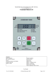
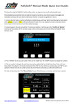
Nortoft Electronic A/S, Sejrupvej 38, DK 7323 Give.
www.nortoftelectronic.com
Program Rain 10-12
Features:
Speed regulation
Pre- and post-irrigation
4 different speeds
Clock
Start time is adjustable
Stop time is shown in the display
Length of the pipe
Actual speed
Battery voltage
Charge regulation
Pressure sensor
Stop sensor
Speed sensor
Motor 1, regulation motor
Motor 2, stop motor
Slowly start of turbine
Slowly opening for inlet of water
GSM SMS messaging for remote control.
User Manual
Ver.1.0 2014-10-07
© Nortoft Electronics 2013
Page 1 of 16
Short hand manual
+
DEPART
PREVOR-
STOP
MENU
-
ARRIVEE
POSTNACH-
START
RESET
PROG
Place machine:
SPEED
30.0m/h
DOSE
22 mm
TIME 7:28 STOP 7:28
STATUS STOP Sensor
Place machine at hydrant, Display shows the same start and
stop time. Wheel out hose to the end of lane. ( ex 250m )
Select Speed:
SPEED
30.0m/h
DOSE
22 mm
TIME 7:56 STOP17:16
STATUS STOP Sensor
Display now shows stop after 8h20m. Press “+” or “-“
keys for the right speed. Speed can be changed during
Irrigation.
SPEED
25.0m/h
DOSE
26 mm
TIME 7:58 STOP17:58
STATUS STOP Sensor
SPEED has decreased, DOSE and STOP has increased.
Start Irrigate, Select PRE- and POST Irrigation.
SPEED
25.0m/h
DOSE
26 mm
TIME 7:58 STOP17:58
STATUS STOP Sensor
Press START For starting, For PRE- and POST Irrigation,
press PRE- and POST- irrigation key’s. STOP time vil
increase when pressing PRE- and Post irrigation.
Starting:
SPEED
25.0m/h
DOSE
26 mm
TIME 8:00 STOP18:38
STATUS Running
Turbine will start, as water pressure increases, after a while
the regulator finds the correct speed.. Irrigation is continued
until end of lane and STOP SENSOR is activated.
-PRE Irrigation
SPEED
25.0m/h
DOSE
26 mm
TIME 8:02 STOP18:38
STATUS PRE Irrigate
-POST Irrigation
SPEED
25.0m/h
DOSE
26 mm
TIME 18:20 STOP18:38
STATUS POST Irri.
Stop:
SPEED
25.0m/h
DOSE
26 mm
TIME 18:38 STOP18:38
STATUS STOP Sensor
If PRE irrigation is activated, Turbine will stop again
immediately and PRE Irrigation takes place. When pre
irrigation time has elapsed, turbine starts and state changes to
Running
If POST irrigation is activated, Turbine will stop at end, when
stop sensor is activated, and POST Irrigation will take place.
Stop sensor is activated, Turbine and Irrigation is shut down.
Machine is ready for disconnection and transport to a new
lane.
User Manual
Ver.1.0 2014-10-07
© Nortoft Electronics 2013
Page 2 of 16
MENU’s
SPEED
30.0m/h
DOSE
22 mm
TIME 14:10 STOP 7:43
STATUS Running
Standard readout
ZONE
1 30.0m/h
DOSE
22 mm
TIME 14:10 STOP 7:43
STATUS Running
Standard readout, Zone Active
DISTANCE
123m
BATTERY
12.8V
CHARGE ON
0.231A
PRE. 0:45 POST 0:45
Press the key MENU 1 time for showing menu 2
PRESS SENSOR
STOP SENSOR
SPEED SENSOR
MOT1 0.0A MOT2
ACTUAL SPEED
START
WORKING HOURS
0m
0m
0m
0m
30.0m/h
30.0m/h
30.0m/h
30.0m/h
SIGNAL 23
NETWORK HOME
A: +45123456
B: +45234567
█
█
█ █
1.8A
22m/h
0:00
Press the key MENU 2 times for showing menu 3
Press the key MENU 3 times for showing menu 4
123h
0m
0m
0m
0m
Press the key MENU 4 times for showing the menu 5
Press the key MENU 5 times for showing the menu 6
( Only when GSM is selected )
When the sign █ is shown in the display, it means that this function is on.
User Manual
Ver.1.0 2014-10-07
© Nortoft Electronics 2013
Page 3 of 16
Standard menu:
SPEED
30.0m/h
DOSE
22 mm
TIME 14:10 STOP 7:43
STATUS Running
Standard readout
SPEED
Speed can be changed at any time during the irrigation, using “+” and “ –“ keys.
ZONE
Actual Zone 1..4, with corresponding speed. Speed can not be changed. ( Zone Active )
DOSE
Dose is calculated by means of constants, and shows the actual mm for irrigation. When SPEED
increases, DOSE decreases. ( Constants 11 and 12 )
TIME
To set the time: first set the speed to 11.1 m/h, and then press the PROG key 3 times,
showing <CONST 1
TIME>, the time can then be set with the “+” and “ –“ keys. When
the battery has been removed the time is 00:00, and is remaining zero until it is set.
STOP
Time when the irrigation is finished incl. pre- and post-irrigation.
STATUS
Status of Irrigating ei:
<Stop Sensor >
<Running
>
<PRE Irrigate >
<POST Irrigate>
<LOW Pressure >
see explanation in STATUS chapter
If the display shows LOW BAT in stead of SPEED, the battery voltage is lower than 11.8 V and the battery need
to be charged.
MENU 2
DISTANCE
123m
BATTERY
12.8V
CHARGE ON
0.231A
PRE. 0:45 POST 0:45
DISTANCE
The remaining length of the pipe. Distance can be changed immediately after pressing
key 3 times, with the “+” and “ –“ keys
PROG
BATTERY
The battery voltage.
CHARGE ON
Shows if the battery is charged from the solar panel.
The battery is charged when the voltage is below 14.0 volt.
PRE.
The actual pre irrigation time.
POST
The actual post irrigation time.
Pre- and Post irrigation time can be changed immediately after pressing PRE- or POSTwith the “+” and “ –“ keys
User Manual
Ver.1.0 2014-10-07
© Nortoft Electronics 2013
Page 4 of 16
MENU 3
PRESS SENSOR
STOP SENSOR
SPEED SENSOR
MOT1 0.0A MOT2
█
█
█ █
1.8A
PRESS SENSOR
Shows if the pressure is high, the marker is on when the water pressure is high.
The machine can only work when the pressure is high.
STOP SENSOR
Shown if the stop switch is activated, the marker is on when the stop switch is on.
The machine can only work when the stop switch is on.
The stop switch has 3 functions:
1: Resets the distance counter.
2: Post-irrigation.
3: Inhibits the pulses to the regulator-motor.
SPEED SENSOR
For testing the speed sensor, the markers is on when the magnets activates the speed sensors.
MOT1, MOT2
The actual Current used by motor. The motor is stopped when the current exceeds 4.5 A. If
current exceeds 4.5A, and the motor has not reached their end position, there is a blocking
inside the valve.
MENU 4
ACTUAL SPEED
START
WORKING HOURS
22m/h
0:00
123h
ACTUAL SPEED
Shows the actual speed that means the speed the machine is running now. This can be used to
check the maximum running speed for the machine, if the Program Rain is set to a much higher
speed than the machine can run.
The actual speed can differ from the set speed, especially in the start, this is not an error because
the Program Rain ensures that the mean speed over 10 m is correct.
START
The starting time, it is a time delay, so the machine will start up to 24 hours later.
To set the staring time, press the " PROG " key 3 times and the time can be set with the ”+” and
“ –“ keys.
WORKING HOURS
The total working hour since the electronic was started the first time.
MENU 5
0m
0m
0m
0m
30.0m/h
30.0m/h
30.0m/h
30.0m/h
0m
0m
0m
0m
This is for irrigation with 4 different speeds in the retraction.
Press the " PROG " key 3 times for programming the zones.
See later in this paper for more details.
User Manual
Ver.1.0 2014-10-07
© Nortoft Electronics 2013
Page 5 of 16
MENU 6
SIGNAL 23
NETWORK HOME
A: +45123456
B: +45234567
SIGNAL
NETWORK
A:
B:
GSM signal strength.
GSM network type
First phone number on “SMS” list.
Second phone number on “SMS” list
Detailed explaination in chapter GSM.
START:
The turbine can only start if the magnet activates the stop sensor (or stop sensors), see menu 3 for controlling the
stop sensor. When the START key is pressed, the main valve opens. Next the by-pass valve closes (the turbine
starts). If the magnet does not activate the stop sensor, it is only the main valve that opens; this is used if the
pressure should be released before disconnecting the hose at the hydrant.
DELAYED START TIME OF IRRIGATION:
First press STOP key for closing for inlet of water. Next press PROG key 3 times ( Menu 3 ) and you can set the
start time. At last choice Pre– and post irrigation if wanted.
STOP:
When the magnet is removed from the stop sensor, the turbine stops and the main valve closes (opens at lowpressure stop).
If post-irrigation is chosen, the turbine stops and after the post-irrigation time, the main valve closes. If the key
STOP is pressed the turbine stops and the main valve closes, regardless of post-irrigation.
SUPERVISION:
The PROGRAM RAIN has a built in system for supervision. The supervision starts to work, if for some reason
the machine irrigates at the same place longer than a specified time. This time is factory adjusted to 20 minutes,
see programming for changing this time. If it is set to 0 there is no supervision. If supervision of speed, data # 20
= 1, is selected, irrigation is stopped when speed was below 50% of selected, in specified time.
SPEED:
The speed is adjusted with the the ”+” and “ –“ keys, the speed first changes by steps of 0.1 m/h, then after 10
steps it changes by 1.0 m/h. The speed can be changed at any time, even while the machine is running. If the
time is checked it shows the new time for the remaining irrigation.
User Manual
Ver.1.0 2014-10-07
© Nortoft Electronics 2013
Page 6 of 16
PRE-IRRIGATION:
Pressing the key PRE- can activate pre-irrigation. The time for pre-irrigation is calculated by the
Program Rain as 8 x the time for running 1 metre at the actual speed.
The constant " 8 " ( constant no. 2 ) can be changed, see programming. If the pre-irrigation is on, the machine
starts and run 1/2 metre, then it stops for the pre-irrigation time.
By pressing the key START the pre-irrigation is cancelled. The magnet at the stop sensor should be in place,
before activating the pre-irrigation.
POST-IRRIGATION:
Post-irrigation can be activated by pressing the key POST- The time for post-irrigation is calculated by the
Program Rain as 8 x the time for running 1 metre at the actual speed. The constant " 8 " (constant no.3) can be
changed, see programming. The post-irrigation starts to count down when the magnet is removed from the stop
sensor. When the magnet is removed, the motor for speed regulation stops the turbine, after the post-irrigation
time the main valve closes, (opens at machines with stop for low pressure). At machines with only one motor for
speed regulation, the turbine starts after the post- irrigation time. By pressing the key START the postirrigation is cancelled. The magnet at the stop sensor should be in place, before activating the post-irrigation.
If Early stop, constant #8, is selected, this function is activated. Shutdown will take place when distance is
reached.
PROGRAMMING OF 4 DIFFERENT SPEEDS:
The display should be set to the 5'th menu.
The pipe should be pulled out before programming, so the computer knows the distance of the field to be
irrigated.
In the following it is assumed that the field length is 400 m.
Press the PROG key 3 times and the display will show:
400m
0m
0m
0m
30.0m/h
30.0m/h
30.0m/h
30.0m/h
0m
0m
0m
0m
The desired speed can now be set, here 25.0 m/h, then press the PROG key once, and the display will show:
400m
0m
0m
0m
25.0m/h
30.0m/h
30.0m/h
30.0m/h
0m
0m
0m
0m
The desired distance can now be set, here 300 m, then press the PROG keys once, and the display will show:
400m
300m
0m
0m
25.0m/h 300m
30.0m/h
0m
30.0m/h
0m
30.0m/h
0m
Now the first zone is programmed, and the procedure is continued for all 4 zones.
Zone 4 automatic ends at 000m.
When zone 4 is programmed press again the PROG key and the display will show:
DELETE PRESS MENU
SAVE
PRESS PROG
If the PROG key is pressed the program is saved and the watering is carried out according to the program.
If the MENU key is pressed the program is deleted and the speed is the same for the whole field.
User Manual
Ver.1.0 2014-10-07
© Nortoft Electronics 2013
Page 7 of 16
STATUS
Status messages in display
EMERGENCY:
Machine has not been started, anyway speed pulses is received and it is trying to
maintain the speed requested.
RUNNING:
Machine is irrigating, everything is working properly
LOW PRESSURE:
Water pressure is below pressure switch treshold. Machine acts depending on
Machine data.
STARTING:
Operator has pressed START key, and start sequens is in process.
START REMOTE:
Machine is starting due to an SMS
START DELAY:
Machine is waiting for start delay to elapse. ( Se menu 4 ).
START PRESSURE:
Machine has started due to pressure rise. Machine is using pressure level, to
start 2’nd machine on string.
START DENIED:
Operator is holding STOP key to prevent PRESSURE and REMOTE start.
STOP USER:
Machine has stopped due to operator STOP.
STOP REMOTE:
Machine has stopped due to an SMS.
STOP SENSOR:
Machine has reached end and is stopped by STOP SENSOR.
STOP DISTANCE:
Machine has reached distance for stop. ( Se constant for early stop )
STOP DELAY:
Machine has reached stop but waits nn Seconds to proceed stop sequence.
STOP DENIED:
Operator is pressing START key, preventing REMOTE stop.
SUPERVISION TIME:
Machine has stopped due to supervision time is elapsed. Machine has not moved
in nn minutes. ( Se constant for supervision time ).
FORCE LOW PRES:
Machine opens valve, to force pressure drop, to stop main pumpe. After 2
minutes, valve closes to prevent draining of pipes.
PRE IRRIGATION:
Machine is performing pre irrigation
POST IRRIGATION:
Machine is performing post irrigation
User Manual
Ver.1.0 2014-10-07
© Nortoft Electronics 2013
Page 8 of 16
There are different constants that can be set by the user.
These constant will be saved for years even if the battery is disconnected.
Programming procedure:
The speed should be adjusted to 11.1 m/h to reach the constants.
Press rapidly the PROG key 3 times to gain access to change the constants.
By subsequent pressing on the PROG key the constant no. will step forward. With the “+” and “ –“ keys the
constant value can be changed.
The PROGRAM RAIN goes back to normal and saves the constant by pressing the key MENU.
If the key MENU is not pressed the Program Rain switches back to normal after 1 minute, and the changes
of the constants are not saved.
CONSTANTS
Const
no.
Note
Fact.
Adj.
Min.
Value
Max.
Value
Description
0
100
-
1
00:00
00:00
2
8
1
15 Pre irrigation
3
8
1
15 Post irrigation
4
20
0
99 Supervision time [minutes]
5
1
1
15 1 English, 2 Danish, 3 German, 4 French, 5 Dutch,
6 Swedish, 7 Spanish, 8 Italian, 9 Polish, 10 Japanese
6
0
0
7
-
0
8
0
0
9
0
0
1000 Early stop [m]
( * Is only performed when Post Irrigation is selected * )
1000 Post irrigation before stop [m]
10
0
0
1000 Distance for alarm [m]
11
40
5
120 Water flow [m3/h]
12
60
5
100 Spacing between irrigation lanes [m]
- Enter 111 to reach machine data
24:00 Time in line 2 is set
2 0 = Stop for high pressure slow shutdown
1 = Stop for low pressure, valve opens and close again after 3 minutes
2 = Motor for stop disconnected
1000 Actual distance, can be set by the keyboard [m]
The constant no. 0 (the code) should be 111 to reach the machine data.
Then press " PROG " and the machine data is shown.
User Manual
Ver.1.0 2014-10-07
© Nortoft Electronics 2013
Page 9 of 16
MACHINE DATA
M.Data Note
no.
Fact.
Adj
Min. Max.
Value Value
Description
0
1
2
3
4
5
6
7
8
9
10
11
12
400
110
1850
12.00
200
10
4
0.89
3
160
2
100
1
0
40
500
5.00
50
5
1
0.70
0
0
1
0
0
1000
200
3000
30.00
1000
40
20
1.00
45
300
5
250
1
13
14
25
0
1
0
25
2
15
0
0
160.0
16
1
0
1
17
0
0
1
18
1
0
1
19
20
0
0
0
0
200
1
21
0
0
1
30
0
0
1
31
-
-
-
Pipe length
[m]
Pipe diameter
[mm]
Reel drum diameter
[mm]
Windings pr. layer
Large drive sprocket
Small drive sprocket
Number of magnets
Ovality
First pulse to main valve
[sec]
Short pulses to main valve
[msec]
Time between short pulses
[sec]
Number of short pulses
Shut-down system,
0 = Only regulator motor
1 = 2 Motors
Preset of pulse to regulation motor at start [sec]
Pressure switch
0 = no pressure switch mounted
1 = pressure switch mounted
2= pressure switch mounted ( only start )
Distance between pulses 40.0-160.0 [mm]
roller Ø80 mm = 62.5 [mm]
0 = running by the formula ( M. data number 0 to 7 )
Speed sensor
0 = round sensor for roller
1 = double sensor
Opening of main valve
0 = fast opening
1 = slow opening
Pressure switch
0 = Main valve stay open at low pressure
1 = Main valve closes at low pressure
Delay from stopsensor to the regulator motor stops the turbine [sec].
Supervision of the right speed
0 = Supervision off.
1 = Supervision on ( 50 % of selected speed )
Meter or foot readings in the display
0 = Meter.
1 = Foot
0 = GSM Modem not active
1 = GSM Modem
2 = GSM Modem, only numbers on SMS list
First phone to call
“A“
31
-
-
-
Second phone to call “ B “
User Manual
Ver.1.0 2014-10-07
© Nortoft Electronics 2013
Page 10 of 16
The Program Rain can be adjusted to 2 different types of sensors.
See, Machine Data #16 Sensor
One is a round sensor 60 mm in diameter and 4 sensors inside; this is only for rollers with one magnet. When the
battery is connected the display for 2 sec. shows VERSION n.n0.
The other is a square sensor, or 2 separate sensors, this is used for rollers with more than one magnet and for
disk's with 1 to 20 magnets.
When the battery is connected the display for 2 sec.showed VERSION n.n1.
Double sensor.
Round sensor
Program Rain 10 18 Pol Connector
Cable connection
Version n.n1
Double sensor
1 + Battery
Brown
12 V
2 - Battery
Blue
3 + Solar Panel
Brown
4 - Solar Panel
Blue
5 Motor 1
Speed Regulation
6 Motor 1
Speed regulation
7 Speed Sensor 1 * Blue
8 Speed Sensor 1 * Black
9 Speed Sensor 2 * Yellow/green
10 Speed Sensor 2 * Brown
11 Stop Sensor
Blue or Brown
12 Stop Sensor
Blue or Brown
13 Motor 2
Stop Motor
14 Motor 2
Stop Motor
15 Pressure
Blue or Brown
16 Pressure
Blue or Brown
17 - BIP
18 + BIP
Program Rain 10
Cable connection Version n.n0 Round sensor
1 + Battery
Brown
12 V
2 - Battery
Blue
3 + Solar Panel
Brown
4 - Solar Panel
Blue
5 Motor 1
Speed Regulation
6 Motor 1
Speed regulation
7 Speed Sensor
Blue
8 Speed Sensor * Black
9 Speed Sensor * Yellow/green (Red)
10 Speed Sensor
Brown
11 Stop Sensor
Blue or Brown
12 Stop Sensor
Blue or Brown
13 Motor 2
Stop Motor
14 Motor 2
Stop Motor
15 Pressure
Blue or Brown
16 Pressure
Blue or Brown
17 BIP 18 BIP +
* If the distance counter count the wrong way,
the speed sensor should be turned.
* If the distance counter count the wrong way,
the cable on terminal 8 and 9 must be interchange.
Program Rain 10 6 Pol Connector
19 + GSM
Brown
20 - GSM
Blue
21 Reserved
22 Reserved
23 Reserved
24 Reserved
+12 V
Technical data
Size ( h*w*d)
Voltage
Current
Fuse
170*140*100
10-15V dc
6 mA ( Idle ) 30 mA ( with GSM )
80 mA ( Light )
5A motor max current
5A Fast
User Manual
Ver.1.0 2014-10-07
© Nortoft Electronics 2013
Page 11 of 16
Fault localisation.
? The turbine can not start by pressing START. Pre-and post-irrigation can not take place.
Answer:
Magnet for stop-sensor is not on its place, or cable or sensor is damaged.
Stop sensor: The mark must be on when the magnet is on place, and it disappears when the magnet is
removed. See menu 3.
A damaged cable can be repaired but absolutely watertight. At least encapsulated in epoxy.
But a new sensor and cable is recommend.
If pressure sensor is used there must be pressure on the water. The mark for pressure must be on.
? None figure in the display.
Answer:
Battery interrupts. Fuse inside the box is blown. The fuse is for wrong connection of + and - .
From the factory there are an extra fuse on a single fuse-holder on the printed circuit.
Fuse 5 A. Battery electric voltage 12 V. See menu 2.
? The clock shows 00:00.
Answer:
If the power has been interrupted the clock will go to zero. Therefore in stead of showing the finish time it is the
number of hours and minutes to the irrigator is finish that is showed. Set the clock and the time to the irrigator is
finish will be showed. See setting the clock.
? Distance meter is not correct and the speeds not correct.
Answer:
See after damaged cable or sensor. The 2 marks must during pulling out the tube appear in order from
the left as following: The first appear the second appear the first disappear the second disappear. During
retraction it must go in opposite order. See menu 3 speed sensor.
It is the same if a roller running on the tube measures the speed.
? Only maybe the half or 2/3 of the real length is counted up.
Answer:
The stop mechanism can be activated a short time by hopping of the tube or if the windings around the drum are
losing. It can cause the magnet removed from the stop sensor a short moment. It will set the counter to zero.
In spite of the meter of the tube is not correct the irrigator will run to the end and stop normal. But incorrect
speed depends of the incorrect registration of the actual layer.
If wanted the correct number of metre can be set in. See CONSTANT no 7.
User Manual
Ver.1.0 2014-10-07
© Nortoft Electronics 2013
Page 12 of 16
The most used combination of different constants:
With constants factory adjusted the machine always will run. But there are different conditions from farm to
farm and there are also different wishes from the farmer. Therefore some constants can be adjusted for local
wishes.
1. Slowly start of turbine. Machine data no. 13. Adjust the to value to 4 sec to start.
Now the valve for control of speed will close about half and continue stepwise until the adjusted speed are
reached. Correct adjustment is: Continuously closing of the valve until the turbine is start running and
stepwise until adjusted speed are reached.
2. Slowly opening for inlet of water. Machine data no. 17. Set the value to 1. =
Opening for the water stepwise.
3. Only 1 motor for speed regulation. Machine data no. 12. Value 0.
Post irrigation must take place as following: When the stop sensor is activated only the retraction stop. After the
time for post irrigation the machine start again and run to the mechanic stop.
4. Start up of no. 2 machine when no. 1 machine reaches the stop.
Machine data no. 14. Value 2.
The machine must be equipped with adjustable pressure switch. Adjust the pressure switch to a point between
the normal pressure and the pressure when the pump will stop.
For instance: Normal pressure 7 bar and pressure for pump stop is 9 bar. Adjust the pressure switch to 8 bar on
both the machines. Start no. 1 machine as normal by pressing start. Set up no. 2 machine but press stop. When
no. 1 machine comes to slowly close down no. 2 machine will start up when the pressure reach 8 bar. Be attend
on that 10 m different on the field level is 1 bar.
5. Stop with low pressure and pressure switch mounted. Constant no. 6. Value 1.
Machine data no. 12 must be value 2. = Stop motor turns in opposite direction. It means that with the same
cable connection to the motor the valve will open for stop. After 2 minute the valve close again
Stop-sensor, stop-button and supervision can open the valve. But the pressure switch can not open the valve
6. Pre-irrigation before the gun reaches the stop.
Constant no 9 can be set to the number of metre where it is wanted that the post irrigation should take place.
User Manual
Ver.1.0 2014-10-07
© Nortoft Electronics 2013
Page 13 of 16
GSM
PR10-12 can handle exernal MC52i ,GSM Modem from, Cinterion.
Irrigator, can be Started, Stopped, or requested for status, only by sending an SMS.
Commands
Start
Stop
Speed ###
Status
Starts machine.
Stops Machine
Set the Speed whitin 3..400 m/h. eg.: Speed 24
Gets the current status of machine.
SMS can be typed in both upper- or lower case or mix.
If you call the modem, from a GSM telephone, you will recieve an SMS containing Status
If machine is operated by keyboard (light in display), SMS is inactive to prevent multible SMS
and remote operating. Upon reception of SMS, User Active is sent return.
Status
SPEED
30.0m/h
DOSE
22 mm
TIME 14:10 STOP18:16
STATUS Running
DISTANCE
123m
BATTERY
12.8V
CHARGE ON
0.231A
SMS, Sent by PR10, contains information about Irrigation
SMS is sent on:
LOW PRESSURE:
STOP SENSOR:
STOP REMOTE:
STOP DISTANCE:
SUPERVISION TIME:
Start the pump, so you get pressure on the machine.
The machine is ready to be moved to a new field.
The machine is stopped using SMS
The machine has reached stop point. (Constant 8 )
The machine has not moved, for nn minutes ( Constant 4 ), due to a
malfunction. Check the machine before continuing.
User Manual
Ver.1.0 2014-10-07
© Nortoft Electronics 2013
Page 14 of 16
How to get started:
Disconnect Electronic from Battery.
Put in the SIM card into an ordinary mobile phone and change the pin code to 1111.
Try to send at receive an SMS, on phone, to verify the SIM card and account is working properly.
Insert the SIM card into the modem.
Operate the eject mechanism (yellow pin
next to the card holder) to open the card
holder by pressing it down with a pen, for
example.
Insert the SIM card in the SIM card holder
and push it back into the housing.
Connect communication- , power- and Antenna cable
Antenna, communication- and power cable, is items from Nortoft Electronics.
User Manual
Ver.1.0 2014-10-07
© Nortoft Electronics 2013
Page 15 of 16
Connect the power and setup machine data #30
0 = GSM Disabled
1 = GSM Enabled, all telephone number is allowed, no Speed change.
2 = GSM Enabled, only telephone number on SMS list, Speed change allowed
SPEED
11.1m/h
DOSE
22 mm
TIME 14:10 STOP 7:43
M.DATA 30
1
See manual for changing machine data.
If selected numbers are used, number could be found in display on PR10 when receiving SMS from actual
phone. Number should always be entered in the same format eg. +44213.. 0044213.. 213..
SPEED
11.1m/h
DOSE
22 mm
TIME 14:10 STOP 7:43
A:
+45123456
See manual for changing machine data.
After Approx. 30-45 seconds moden should be connected to network.
SIGNAL 23
NETWORK HOME
A: +45123456
B: +45234567
Signal strength, 0 – 31,and network should show up in display
menu #6
A Signal strength at 10 og higher to work properly.
A Signal strength at 99 indicates signal error.
Modem has a LED showing status
Operating states
LED
POWER DOWN
Off
– Network search or
– no SIM card is inserted
– no PIN is entered
– no GSM network is available
STANDBY
(registered in the network)
Connection (TALK)
Flashes rapidly
Flashes slowly
On
When an SMS is Received, following is showed on Display:
Receiving SMS
#: +45123456
Status
Receiving SMS, Incomming phone number and 40 character
of message, Any SMS can be received, but only known
commands are accepted.
When an SMS is Sent, following is showed on Display:
Sending SMS
#: +45123456
Sending SMS, Outgoing phone number and current machine
status.
Status Running
User Manual
Ver.1.0 2014-10-07
© Nortoft Electronics 2013
Page 16 of 16