1
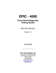
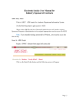
MGS-2
Mini-Ganzfeld
System
USER'S MANUAL
Version 1.4
LKC Technologies, Inc.
2 Professional Drive, Suite 222
Gaithersburg, MD 20879 USA
(301) 840-1992
(800) 638-7055
[email protected]
0086
WARRANTY
LKC Technologies, Inc. unconditionally warrants this instrument to be free from defects in materials and
workmanship, provided there is no evidence of abuse or attempted repairs without authorization from LKC
Technologies, Inc. This Warranty is binding for one year from date of initial delivery and is limited to:
servicing and/or replacing any instrument, or part thereof, returned to the factory for that purpose with
transportation charges prepaid and which are found to be defective. This Warranty is made expressly in
lieu of all other liabilities and obligations on the part of LKC Technologies, Inc.
DAMAGE UPON ARRIVAL. Each instrument leaves our plant, after rigorous tests, in perfect operating
condition. The instrument may receive rough handling and damage in transit. The shipment is insured
against such damage. The Buyer must report, in writing, immediately any concealed or apparent damage to
the last carrier. Report any damage also to us, and issue an order for replacement or repair.
DEFECTS OCCURRING WITHIN WARRANTY PERIOD. Parts of units may develop defects which
no amount of initial testing will reveal. The price of our instruments makes provision for such service, but
it does not:
1.
2.
3.
Provide for transportation charges to our factory for service,
Provide for services not performed or authorized by us,
Provide for the cost of repairing instruments that have obviously been abused or subjected to
unusual environments for which they have not been designed.
We will be happy at any time to discuss by phone, letter, FAX, or e-mail suspected defects or
aspects of instrument operation that may be unclear. We advise you to inform us by phone, letter FAX, or
e-mail of the nature of the defect before returning an instrument for repair. Often, a simple suggestion will
solve the problem without returning an instrument to the factory. If we are unable to suggest something
that solves the problem, we will advise you as to what parts of the equipment should be returned to the
factory for service.
DEFECTS OCCURRING AFTER WARRANTY PERIOD. Charges for repairs after the warranty
period will be based upon actual hours spent on the repair at the then prevailing rate, plus cost of parts
required and transportation charges, or you may elect to purchase an extended warranty.
We will be happy to discuss by phone, letter, FAX, or e-mail any problem you may be experiencing.
LKC Technologies, Inc.
Customer Support
(800) 638-7055
FAX Number
(301) 330-2237
e-mail
[email protected]
Important Notice
The MGS-2 Mini-Ganzfeld System is approved for human use
by the US Food and Drug Administration (FDA) only when used with
an LKC Technologies UTAS or EPIC visual electrodiagnostic test
system, or when sold by another manufacturer as part of their
complete system. This notice does not affect use of the device on
animals.
Introduction
The MGS-2 is a stand-alone monocular ganzfeld photic stimulator designed for use in visual
electrodiagnostic testing. The stimulator conforms to the requirements of the ISCEV Standard for Clinical
Electroretinography. The MGS-2 is designed to be used with an electrophysiology recording system to
perform the electroretinogram (ERG) or flash visually evoked potential (flash VEP).
The equipment has been tested in accordance with IEC60601-1, and meets all requirements for
Non-isolated Patient Connections, i.e., electromedical apparatus with intentional electrical or conductive
contact, other than contacts intended to be connected to the exposed heart or to a foreign conductive
pathway to the heart or great vessels.
1
Setting up the MGS-2
Before you can use the MGS-2, you must set it up, connect it to your recording system, and
configure it to match your recording system.
The MGS-2 system consists of two parts:
C
C
The Main Unit (the box)
The Hand held Mini-Ganzfeld Stimulator (called the Kürbisfeld)
Step 1
Make sure the MGS-2 is properly configured to match your recording system. See the section titled
Configuring the MGS-2 to Match Your System on the next page. If you have trouble figuring this out,
call or send a fax/e-mail to the customer support at LKC for assistance.
Step 2
Plug the Kürbisfeld into the Main Unit.
L
Make sure the power to the Main Unit is off before connecting or disconnecting the
Kürbisfeld.
Step 3
Plug the Main Unit into the power mains. If you are using the MGS-2 with an LKC EPIC or UTAS
system, plug the unit into one of the outlets on the back of the Interface Unit or MGIT-100. If you are
using the MGS-2 with a system from another manufacturer, you may plug the MGS-2 directly into a wall
outlet.
L
The MGS-2 uses a “Universal” power supply. As such, it can be connected to any
AC power source from 100 Volts to 220 Volts at either 50 or 60 Hz.
Step 4
Connect the MGS-2 to your recording system using the cable provided with the unit. See the
instructions in Configuring the MGS-2 to Match Your System on the next page to determine how to
connect the cable.
L
You are now ready to use your MGS-2 stimulator.
2
Configuring the MGS-2 to Match Your System
To function properly as a stimulator, the MGS-2 must communicate with your recording system.
The MGS-2 can do this in one of two ways:
C
The MGS-2 can accept a trigger signal from your recording equipment and trigger its stimulus by
this signal.
C
The MGS-2 can provide a trigger signal to your system to inform it that the stimulus has been
triggered, by pressing the STIM button either on the Main Unit or on the stimulator.
L
The first step in configuring the MGS-2 is to decide whether the recording system
or the MGS-2 will trigger the stimulus.
If the MGS-2 is to accept a trigger signal from your recording system:
C
Connect a cable from the trigger output of your recording system to the connector marked
TRIGGER IN on the rear of the MGS-2.
You must also make sure that the MGS-2 is set to properly trigger from your recording system.
The MGS-2 accepts a TTL-level (0 to 5 V) trigger input signal. As it comes from the factory, the MGS-2
will fire stimulus each time the trigger input signal, applied to TRIGGER IN, goes from low (0 V) to high
(5 V). Consult the manual for your recording system or measure its trigger signal with an oscilloscope to
determine its polarity.
Warning: If the Trigger In Polarity Switch is improperly set, the MGS-2 may appear
to operate correctly, but the timing of the stimulus will be incorrect.
If the trigger signal from your system goes from high (5 V) to low (0 V), set the trigger-in-polarity switch
SW9-3 on PCB 310134 to the on position.
If the MGS-2 is to provide a trigger signal to your recording system:
C
Connect a cable from the connector marked TRIGGER OUT on the rear of the MGS-2 to the
external trigger input of your recording system.
You must also make sure that the MGS-2 is set to send the proper trigger to your recording system.
As it comes from the factory, the MGS-2 sends a TTL-level trigger signal to TRIGGER OUT that goes
from low (0 V) to high (5 V) to the recording system each time a stimulus occurs. Consult the manual for
your system to determine if this is the correct polarity.
3
Warning: If the Trigger Out Polarity Switch is improperly set, the MGS-2 may
appear to operate correctly, but the timing of the stimulus will be incorrect.
If your system requires a trigger signal going from high (5 V) to low (0 V), set the trigger-out-polarity
switch SW9-2 on PCB 310134 to the on position.
Setting the MGS-2 switches.
SW9
PCB 310134
1234
Remove the four screws on the bottom of the MGS-2 box and lift off the top cover.
The rocker DIP switch SW9 is located on the circuit board PCB 310134 mounted to the back of the
front panel. You will need to slide the front panel out of the bottom cover to gain access to the switch.
Turn on or turn off switches of SW9 according to the following tables.
SW9-1, Trigger Out Select Switch
ON*
TTL - level trigger output signal
OFF
Open - Collector trigger output signal
SW9-2, Trigger Out Polarity Switch
ON
Trigger output goes high to low at stimulus
OFF*
Trigger output goes low to high at stimulus
SW9-3, Trigger In Polarity Switch
ON
Stimulus triggers on high to low transition
OFF*
Stimulus triggers on low to high transition
* System default settings.
4
Using the MGS-2
After you have properly set up your MGS-2, you are ready to start using it.
MGS-2
Rev 1.1
SEL
LKC Technologies, Inc.
MGS - 2
BACK
LIGHT
STIM
Turning it On and Off
The power switch for the MGS-2 is located on the rear of the unit. It s the only switch on the Main
Unit that is not labeled. When you turn the MGS-2 on, the LCD display window on the Main Unit will
glow with green light and show the information as above, and the 7 push buttons will turn red. Whether the
fixation light in the Kürbisfeld glows a dim red or remains off depends on the last setting before the system
was previously powered off.
After 3 seconds, the LCD display will turn to the Main Menu.
Main Menu
The Main Menu displays function names (also sub-menu names) and the current settings of
flash/flicker intensity and back light brightness:
Main Menu
$ Flash
Background
Flicker
B: 30 cd/m2 F: 0 dB
MGS-2 can save all the settings in its memory. Each time when the system is powered on, the
Main Menu will show the last settings before it was powered off. The first time you power your MGS-2
the default settings of the system should be shown as above, which means:
Stimulus Type:
Background Light:
Flash/Flicker:
Flash
30cd/m2
0dB (2.5cdAs/m2)
5
Pressing the BACK LIGHT button on the front panel or the BKLT button on the back of the
Kürbisfeld will turn on the background light.
The brightness of background light is 30 cd/m . The status of fixation light, ON or OFF can be
selected in the Background sub-menu.
Pressing the STIM button either on the front panel or on the back of the Kürbisfeld will trigger the
stimulus. At the same time, the system will send a trigger output pulse to the TRIGGER OUT BNC
connector on the rear panel.
L
The STIM and BACK LIGHT buttons are operational only when the Main Menu is
displayed.
MGS-2 provides 2 kinds of stimuli: Flash and Flicker. The features of each stimulus can be set in
the according sub-menu. Flash/flicker of any available intensity can be triggered individually or with
background light.
When the STIM button is pressed, it will
C
fire a single flash if the cursor arrow points to Flash or Background.
C
start flicker until the STIM button is released if the arrow points to Flicker.
L
If the MGS-2 is set to accept a trigger signal from your recording system, make
sure that external trigger input signals can be accepted by the MGS-2 only at the
Main Menu.
Each trigger input pulse fires a single flash no matter the cursor arrow is pointing to Flash, Flicker
or Background. Flicker can be obtained by sending periodical pulses to the unit at any rate less than
100Hz.
Use buttons • – » and º to select functions/sub-menus. Press the SEL button to switch to the
according sub-menu. Features for any function, e.g., intensity, rate, etc. can be re-selected in the submenus.
Flash Menu
Flash
Intensity:
~
0dB
The value beside the ~ symbols is the current flash level. Using buttons » or º can make a
change. Once button » or º is pressed, the symbol ~ will turn to a pointer $, which indicates that no
option is selected yet. Press the SEL button to select the dB value. After a value is selected, shown by the
pointer turning back to the star, press SEL again to return to the Main Menu.
6
Available flash intensities are: -25 through +5 dB in 5dB steps.
(0 dB: 2.5 cdAs/m2)
Flicker Menu
Flicker
Intensity:
Flicker Rate:
~
~
0dB
30Hz
The Intensity/Flicker Rate features with ~ symbols are the current settings. Use buttons • and – to
point to one of the two features. Press button » or º to make a change to the feature. Once button » or º
is pressed, the symbol ~ will turn to a pointer $, which indicates that no option for the feature is selected
yet. Press the SEL button to select an option. After both two features are selected, press SEL again to
return to the Main Menu.
Flicker Intensity:
Flicker Rate:
-25 through +5 dB in 5dB steps.
5Hz through 60Hz in 5Hz steps.
Background Menu
Background
Intensity:
Fixation:
~30 cd/m²
~ON OFF
Background intensity is 30cd/m². The current fixation status is indicated by the ~ symbol. Pressing
button » or º can toggle between ON and OFF. Once button » or º is pressed, the symbol ~ will turn to
a pointer $, which indicates that no option for the feature is selected yet. Press the SEL button to select
the option then press SEL again to return to the Main Menu.
Computer Control
MGS-2 is also computer-controllable using a RS-232 serial port as an additional option. Please
contact LKC for further information on how to purchase this feature.
Presenting Stimuli to the Patient
To present a stimulus to the patient, hold the Kürbisfeld up to the patient’s eye.
7
L
C
The ERG requires a ganzfeld stimulus, and the Kürbisfeld must be close to the patient’s eye to
assure that light enters the eye evenly from all directions. Be careful that the Kürbisfeld does not
dislodge the corneal electrode when it is placed over the eye.
C
Flash VEP does not require a ganzfeld stimulus, and the Kürbisfeld may be held up to 10 cm (4
inches) from the patient’s eye.
Press the STIM button on the Kürbisfeld to present a stimulus to the patient.
If the Main Unit is set to Flash, a single flash of the selected intensity will be presented. If the
Main Unit is set to Flicker, a flickering stimulus will be presented until the STIM button is released.1
MGS-2 Cleaning and Maintenance
The outer plastic surfaces of the MGS-2 system may be cleaned with a damp cloth and any mild
detergent. The inner surface of the Ganzfeld globe must not be touched or wiped by any material
because of the fragility of the reflective coating. It is highly recommended that the Ganzfeld be
protected with the supplied cover any time it is not in use. Use low-pressure filtered compressed air
only to remove any dirt or dust that may have accumulated inside the globe. If the reflective coating
becomes damaged, the Ganzfeld must be returned to LKC Technologies for refinishing.
1
The Main Unit will send a pulse to the Trigger Out connector for each flash during this period.
8