1
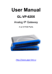
User Manual
GL-VP-6222 и
GL-VP-6244
Analog IP Gateway
2FXS&2FXO Ports OR 4FXS&4FXO Ports
http://www.giga-link.ru
GL-VP-62xx User Manual
Table of Content
1
2
3
4
5
6
7
8
9
WELCOME ................................................................................................................... 3
1.1
Gateway GL-VP-62xx Overview .................................................................... 3
1.2
Safety Compliances ....................................................................................... 3
1.3
Warranty ......................................................................................................... 4
CONFIGURE YOUR GL-VP-62XX .............................................................................. 4
2.1
Equipment Packaging .................................................................................... 4
2.2
Connect The GL-VP-62XX............................................................................. 4
2.3
GL-VP-62XX Back Panel ............................................................................... 4
2.4
GL-VP-62XX Display Panel ........................................................................... 5
GL-VP-62XX FEATURES ............................................................................................ 6
3.1
Software Features Overview ......................................................................... 6
3.2
Hardware specification................................................................................... 8
CALL FEATURES ........................................................................................................ 8
BASIC OPERATIONS .................................................................................................. 9
5.1
Understanding GL-VP-xxxx Voice Prompts ................................................... 9
5.2
Placing A Phone Call.................................................................................... 11
5.2.1
Phone or Extension Numbers............................................................... 11
5.2.2
Direct IP Calls ....................................................................................... 12
5.3
Call Hold ....................................................................................................... 12
5.4
Call Waiting .................................................................................................. 13
5.5
Call Transfer ................................................................................................. 13
5.6
3-Way Conferencing .................................................................................... 14
5.7
PSTN Pass Through/Life Line ..................................................................... 14
5.8
Sending And Receiving Fax ......................................................................... 14
CONFIGURATION GUIDE ......................................................................................... 15
6.1
Configuration With Web Browser................................................................. 15
6.2
End User Configuration................................................................................ 15
6.3
Super User Settings ..................................................................................... 19
6.4
Configuring The FXS Channels ................................................................... 22
6.5
FXS Profile ................................................................................................... 23
6.6
Configuring The FXO Channels ................................................................... 33
6.7
FXO Profiles ................................................................................................. 35
6.8
Saving The Configuration Changes ............................................................. 43
6.9
Rebooting From Remote.............................................................................. 44
SOFTWARE UPGRADE ............................................................................................ 44
RESTORE FACTORY DEFAULT SETTINGS............................................................ 45
TECHNICAL SUPPORT CONTACT .......................................................................... 46
Copyright © 2009-2011 GigaLink
Page 2 of 46
GL-VP-62xx User Manual
1 WELCOME
Thank you for purchasing the Gigalink GL-VP-62XX Analog FXS IP Gateway. The
GL-VP-62XX offers an easy to manage, easy to configure IP communications solution for
any business with virtual and/or branch locations. The GL-VP-62XX supports popular
voice codecs and is designed for full SIP compatibility and interoperability with 3rd party
SIP providers, thus enabling you to fully leverage the benefits of VoIP technology,
integrate a traditional phone system into a VoIP network, and efficiently manage
communication costs.
This manual will help you learn how to operate and manage your GL-VP-xxxx FXS Analog
IP Gateway and make the best use of its many upgraded features including simple and
quick installation, multi-party conferencing, This IP Analog Gateway is very easy to
manage and scalable, specifically designed to be an easy to use and affordable VoIP
solution for the small – medium business or enterprise.
1.1 Gateway GL-VP-62XX Overview
The new GL-VP-62XX series has a compact and quiet design (no fans) and offers superb
audio quality, rich feature functionality, strong security protection, and good manageability.
It is auto-configurable, remotely manageable and scalable.
The GL-VP-62XX features 4 or 8-port FXS interface for analog telephones, dual
10M/100Mbps network ports with integrated router, PSTN life line in case of power failure,.
In addition, it supports the option of 2 SIP Server profiles, caller ID for various
countries/regions, T.38 fax, flexible dialing plans, security protection (SIPS/TLS),
comprehensive voice codecs including G.711 (a/u-law), G.723.1, G.726(16/24/32/48 bit
rates), G.729A/B/E and iLBC(Pending).
Caution: Changes or modifications to this product not expressly approved by Gigalink Co
LTD, or operation of this product in any way other than as detailed by this User Manual,
could void your manufacturer warranty.
Information in this document is subject to change without notice. No part of this document
may be reproduced or transmitted in any form or by any means, electronic or mechanical,
for any purpose without the express written permission of Gigalink Co LTD.
1.2 Safety Compliances
The GL-VP-62XX is compliant with various safety standards including FCC/CE. Its power
adaptor is compliant with UL standard. Warning: use only the power adapter included
in the GL-VP-62XX package. Using an alternative power adapter may permanently
damage the unit.
Copyright © 2009-2011 GigaLink
Page 3 of 46
GL-VP-62xx User Manual
1.3 Warranty
Gigalink has a reseller agreement with our reseller customer. End users should contact
the company from whom you purchased the product for replacement, repair or refund.
If you purchased the product directly from Gigalink, contact your Gigalink Sales and
Service Representative for a RMA (Return Materials Authorization) number. Gigalink
reserves the right to remedy warranty policy without prior notification.
2 CONFIGURE YOUR GL-VP-62XX
Connecting your GL-VP-62XX is easy. Before you begin, please verify the contents of the
GL-VP-62XX package.
2.1 Equipment Packaging
Unpack and check all accessories. The GL-VP-62XX package contains:
One GL-VP-62XX VoIP adapter
One universal power supply
One Ethernet cable
2.2 Connect The GL-VP-62XX
Managing the GL-VP-62XX gateway and connecting the unit to the VoIP network is very
simple. Follow these four (4) steps to connect your GL-VP-62XX gateway to the Internet
and access the unit‟s configuration pages.
1. Connect standard touch-tone analog phones to the FXS1-FXS4 ports.
2. Insert the Ethernet cable into the WAN port of GL-VP-62XX and connect the other end
of the Ethernet cable to an uplink port (a router or a modem, etc.)
3. Connect a PC to the LAN port of GL-VP-62XX for initial configuration or if it is being
used as a router.
4. Plug the power adapter into the GL-VP-62XX and into a power outlet.
2.3 GL-VP-62XX Back Panel
Figure 1: Diagram of GL-VP-62XX Back Panel
Copyright © 2009-2011 GigaLink
Page 4 of 46
GL-VP-62xx User Manual
TABLE 1:
Definitions Of The GL-VP-xxxx Connectors
LAN
WAN
PSTN Line
RESET
DC 9V 2A
Connect the LAN port with an Ethernet cable to your
PC.
Connect to the internal LAN network or router.
1 port
Factory Reset button. Press for 8 seconds to reset
factory default settings.
Power adapter connection
FXS1 – FXS4
FXS port to be connected to analog phones / fax
machines
FXO1 – FXO4
FXO ports to be connected to physical PSTN lines from
a traditional PSTN PBX or PSTN Central Office.
Once the GL-VP-xxxx is turned on and configured, the front display panel indicates the
status of the unit.
2.4 GL-VP-62XX Display Panel
Figure 2: Diagram Of GL-VP-62XX Display Panel
TABLE 2:
Definitions Of The GL-VP-xxxx Display Panel
Power LED
RUN LED
LAN LED
Copyright © 2009-2011 GigaLink
Indicates Power. Remains ON when Power is connected
and turned ON.
blinking after boot-up.
Indicates LAN port activity
Page 5 of 46
GL-VP-62xx User Manual
WAN LED
LEDs 1 - 8
Indicates WAN port activity
Indicate status of the respective FXS Ports on the back
panel
Busy - ON (Solid Green)
Available - OFF
Slow blinking FXS LEDs indicates Voice Mail for that port.
NOTE:
Flast blinking of RUN, WAN LED together indicates a firmware upgrade or
provisioning state.
LEDs POWER, and WAN are ON and READY blinking when device is up and
running.
3 GL-VP-62XX FEATURES
The GL-VP-62XX is a next generation IP voice gateway that is interoperable and
compatible with leading IP-PBXs, SoftSwitches and SIP platforms. The GL-VP-62XX
series is auto-configurable, remotely manageable and scalable. There are two models,
the GL-VP-62XX, each offering superb voice quality, traditional telephony functionality,
easy deployment, and 2 or 4 FXS&FXO ports respectively. Each model features flexible
dialing plans, PSTN failover, integrated call routing to support a pure IP network call and
an external power supply.
3.1 Software Features Overview
2 or 4 FXS ports
2 or 4 FXO ports
Two RJ-45 ports (switched or routed)
Multiple SIP accounts & profiles (2 or 4 accounts / choice of 2 profiles per account)
Supports Voice Codecs: G711(a/μ, Annex I & II), G723.1A, G726 (ADPCM with
16/24/32/40 bit rates), G729 A/B/E, Ilbc(Pending)
T.38 Fax
Comprehensive Dial Plan support for Outgoing calls.
G.168 Echo Cancellation
Voice Activation Detection (VAD), Comfort Noise Generation (CNG), and Packet
Loss Concealment (PLC)
Supports PSTN/PBX analog telephone sets or analog trunks
TABLE 3:
GL-VP-62XX SOFTWARE FEATURES
Copyright © 2009-2011 GigaLink
Page 6 of 46
GL-VP-62xx User Manual
GL-VP-62XX FXS Analog Gateway Series
Telephone Interfaces
Network Interface
LED Indicators
GL-VP-xxxx 6104: 4 ports, 4 SIP accounts & choice of 2
profiles
GL-VP-xxxx 6108: 8 ports, 8 SIP accounts & choice of 2
profiles
FXS/FXO, RJ-11
Two (2) 10M/100 Mbps, RJ-45
Power and Line LEDs
Voice over Packet
Capabilities
Voice Activity Detection (VAD) with CNG (comfort noise
generation) and PLC (packet loss concealment), AEC
with NLP, Packetized Voice Protocol Unit (supports
RTP/RTCP and AAL2 protocol), G.168 compliant Echo
Cancellation, Dynamic Jitter Buffer, Modem detection &
auto-switch to G.711
Voice Compression
G.711 + Annex I (PLC), Annex II (VAD/CNG format)
encoder and decoder, G.723.1A, G.726(ADPCM with
16/24/32/40 bit rates), G.729A/B/E, iLBC G.726 provides
proprietary VAD, CNG, and signal power estimation
Voice Play Out unit (reordering, fixed and adaptive jitter
buffer, clock synchronization), AGC (automatic gain
control), Status output, Decoder controlling via voice
packet header
DHCP Server/Client
Yes, NAT Router or Switched Mode
Fax over IP
T.38 compliant Group 3 Fax Relay up to 14.4kpbs and
auto-switch to G.711 for Fax Pass-through, Fax
Datapump V.17, V.19, V.27ter, V.29 for T.38 fax relay
QoS
IP Transport
DTMF Method
IP Signaling
Provisioning
Control
Management
Dial Plan
UPnP Support
Power
Mounting
Short and long haul
Caller ID
Copyright © 2009-2011 GigaLink
Diffserve, TOS, 802.1 P/Q VLAN tagging
RTP/RTCP
flexible DTMF transmission method, User interface of
In-audio, RFC2833, and/or SIP Info
SIP (RFC 3261)
TFTP, HTTP, HTTPS (pending)
TLS/SIPS
Syslog support, HTTPS (pending), Telnet, remote
management using Web browser
Yes
Yes
Output: 9VDC / Input: 100–240 VAC/50-60 Hz
Rack mount, Wall mount, Desktop
REN3: Up to150 ft on 24 AWG line
Bellcore Type 1 & 2, ETSI, BT, NTT, and DTMF-based
CID
Page 7 of 46
GL-VP-62xx User Manual
Polarity Reversal / Wink
EMC
Safety
Yes
EN55022/EN55024 and FCC part15 Class B
UL
3.2 Hardware specification
The hardware specifications of the GL-VP-xxxx FXS series are detailed in Table 4.
TABLE 4: Hardware Specification Of GL-VP-62XX
Ports
LAN interface
2 or 4 FXS/FXO Ports
2 x RJ45 10/100Mbps (switched or routed)
LED
4 or 8 LEDs (GREEN)
Universal Switching
Power Adaptor
Input: 100-240V AC, 50/60Hz, 0.5A Max
Output: 9V DC, 2A
UL certified
Dimension
225mm (L) x 135mm (W) x 35mm (H)
Weight
0.85 kg
Temperature
32~104°F / 0~40°C
Humidity
10% - 90% (non-condensing)
Compliance
FCC, CE
4 CALL FEATURES
The GL-VP-62XX supports the traditional telephony features available in a PBX as well as
additional advanced telephony features.
TABLE 6: Call Features Table (Star Code)
Key
Call Features
*30
Block CallerID (for all-config change)
*31
Send CallerID (for all-config change)
*67
Block CallerID (per call)
*82
*47
Send CallerID (per call)
Direct IP Calling. Dial “*47” + “IP address”. No dial tone will be
Copyright © 2009-2011 GigaLink
Page 8 of 46
GL-VP-62xx User Manual
played in the middle.
Detail see Direct IP Calling section on page 12.
*50
Disable Call Waiting (for all-config change)
*51
Enable Call Waiting (for all-config change)
*69
Call Return Service: Dial *69 and the phone will dial the last
incoming phone number received.
*70
Disable Call Waiting
*71
Enable Call Waiting (Per Call)
*72
Unconditional Call Forward: Dial “*72” and then the forwarding
number followed by “#”. Wait for dial tone and hang up. (dial tone
indicates successful forward)
*73
Cancel Unconditional Call Forward:
tone, then hang up.
*78
Enable Do Not Disturb (DND): When enabled all incoming calls will
be rejected.
*79
Disable Do Not Disturb (DND): When disabled, incoming calls will
be accepted.
*87
Blind Transfer
*90
Busy Call Forward: Dial “*90” and then the forwarding number
followed by “#”. Wait for dial tone then hang up.
*91
Cancel Busy Call Forward:
(Per Call)
Dial “*73” and wait for dial
dial “*91”. Wait for dial tone. Hang up.
*92
Delayed Call Forward: Dial “*92” and then the forwarding number
followed by “#”. Wait for dial tone then hang up.
*93
Cancel Delayed Call Forward:
Dial “*93” for a dial tone, then hang up.
Flash/Hook
If user hears call waiting beep, flash/hook will switch to the new
incoming call. Also used to switch to a new channel for a new call.
#
Pressing pound sign will serve as Re-Dial key.
5 BASIC OPERATIONS
5.1
Understanding GL-VP-xxxx Voice Prompts
GL-VP-62XX has a stored voice prompt menu for quick browsing and simple configuration.
To enter the voice prompt menu, press *** on the standard analog phone connected to any
FXS port.
Copyright © 2009-2011 GigaLink
Page 9 of 46
GL-VP-62xx User Manual
TABLE 5: Definitions Of The GL-VP-xxxx Voice Prompts
Menu
Main
Menu
Voice Will Say the
Following:
“Enter a Menu Option”
Enter “*” for the next menu option
Enter “#” to return to the main menu
Enter 01 – 05, 07,10 - 17, 47, 86 or 99
Menu option
01
“DHCP Mode”, “PPPoE
Enter „9‟ to toggle the selection
Mode” or “Static IP Mode”
If user selects “Static IP Mode”, user
need configure all the IP address
information through menu 02 to 05.
If user selects “Dynamic IP Mode”, the
device will retrieve all IP address
information from DHCP server
automatically when user reboots the
device.
02
“IP Address “ + IP address
The current WAN IP address is
announced Enter 12-digit new IP
address if in Static IP Mode.
03
04
05
07
“Subnet “ + IP address
Same as Menu option 02
“Gateway “ + IP address
Same as Menu option 02
“DNS Server “ + IP address
Same as Menu option 02
Preferred Vocoder
Enter “9” to go to the next selection in
the list:
PCM U
PCM A
iLBC
G-726
G-723
G-729
10
12
“MAC Address”
Announces the Mac address of the unit.
WAN Port Web Access
Enter “9” to toggle between enable and
disable
13
Firmware Server IP
Address
Announces current Firmware Server IP
address. Enter 12 digit new IP address.
14
Configuration Server IP
Address
Announces current Config Server Path
IP address. Enter 12 digit new IP
address.
15
Upgrade Protocol
Upgrade protocol for firmware and
configuration update.
Enter “9” to toggle between TFTP and
Copyright © 2009-2011 GigaLink
Page 10 of 46
GL-VP-62xx User Manual
HTTP
16
17
47
Firmware Version
Firmware version information.
Firmware Upgrade
Firmware upgrade mode. Enter “9” to
rotate among the following three
options:
“Direct IP Calling”
“Invalid Entry”
1.
2.
always check
check when pre/suffix changes
3.
never upgrade
Enter the target IP address to make a
direct IP call, after dial tone. (See
“Make a Direct IP Call”.)
Automatically returns to Main Menu
Five Success Tips when using the Voice Prompt
1. “*” shifts down to the next menu option
2. “#” returns to the main menu
3. “9” functions as the ENTER key in many cases to confirm an option
4. All entered digit sequences have known lengths - 2 digits for menu option and 12 digits
for IP address. For IP address, add 0 before the digits if the digits are less than 3 (i.e. 192.168.0.26 should be key in like 192168000026. No decimal is needed).
5. Key entry can not be deleted but the phone may prompt error once it is detected
5.2
Placing A Phone Call
5.2.1 Phone or Extension Numbers
1. Dial the number directly and wait for 4 seconds (Default “No Key Entry Timeout”); or
2. Dial the number directly and press # (Use # as dial key” must be configured in web
configuration).
3. If you want to call another FXS port press ***7 and the number of port.
Examples:
1. Dial an extension directly on the same proxy, and then press the # or wait for 4 seconds.
2. Dial an outside number, first enter the prefix number (usually 1+ or international code)
followed by the phone number. Press # or wait for 4 seconds. Check with your VoIP
service provider for further details on prefix numbers.
Copyright © 2009-2011 GigaLink
Page 11 of 46
GL-VP-62xx User Manual
5.2.2 Direct IP Calls
Direct IP calling allows two parties, that is, a FXS Port with an analog phone and another
VoIP Device, to talk to each other in an ad hoc fashion without a SIP proxy.
Elements necessary to completing a Direct IP Call:
1. Both GL-VP-xxxx and other VoIP Device, have public IP addresses, or
2. Both GL-VP-xxxx and other VoIP Device are on the same LAN using private IP
addresses, or
3. Both GL-VP-xxxx and other VoIP Device can be connected through a router using
public or private IP addresses (with necessary port forwarding or DMZ).
GL-VP-xxxx supports two ways to make Direct IP Calling:
Using IVR
1. Pick up the analog phone then access the voice menu prompt by dial “***”
2. Dial “47” to access the direct IP call menu
3. Enter the IP address using format ex. 192*168*0*160 after the dial tone.
Using Star Code
1. Pick up the analog phone then dial “*47”
2. Enter the target IP address using same format as above.
Note: NO dial tone will be played between step 1 and 2.
Destination ports can be specified by using “*” (encoding for “:”) followed by the port
number.
Examples:
a) If the target IP address is 192.168.0.160, the dialing convention is
*47 or Voice Prompt with option 47, then 192*168*0*160.
Followed by pressing the “#” key if it is configured as a send key or wait 4 seconds. In this
case,
the default destination port 5060 is used if no port is specified.
b) If the target IP address/port is 192.168.1.20:5062, then the dialing convention would be:
*47 or Voice Prompt with option 47, then 192*168*0*160*5062 followed by pressing the
“#” key
If it is configured as a send key or wait for 4 seconds.
NOTE: When completing direct IP call, the “Use Random Port” should set to “NO”. You
cannot make direct IP calls between FXS1 to FXS2 since they are using same IP.
5.3
Call Hold
Place a call on hold by pressing the “flash” button on the analog phone (if the phone has
that button).Press the “flash” button again to release the previously held Caller and
resume conversation. If no “flash” button is available, use “hook flash” (toggle on-off hook
quickly). You may drop a call using hook flash.
Copyright © 2009-2011 GigaLink
Page 12 of 46
GL-VP-62xx User Manual
5.4
Call Waiting
Call waiting tone (3 short beeps) indicates an incoming call, if the call waiting feature is
enabled. Toggle between incoming call and current call by pressing the “flash” button.
First call is placed on hold. Press the “flash” button to toggle between two active calls.
5.5
Call Transfer
Blind Transfer
Assume that call Caller A and B are in conversation. A wants to Blind Transfer B to C:
3. Caller A presses FLASH on the analog phone to hear the dial tone.
4. Caller A dials *87 then dials caller C‟s number, and then # (or wait for 4 seconds)
5. Caller A will hear the confirm tone. Then, A can hang up.
NOTE: “Enable Call Feature” must be set to “Yes” in web configuration page.
Caller A can place a call on hold and wait for one of three situations:
1. A quick confirmation tone (similar to call waiting tone) followed by a dial tone. This
indicates the transfer is successful (transferee has received a 200 OK from transfer target).
At this point, Caller A can either hang up or make another call.
2. A quick busy tone followed by a restored call (on supported platforms only). This means
the transferee has received a 4xx response for the INVITE and we will try to recover the
call. The busy tone is just to indicate to the transferor that the transfer has failed.
3. Continuous busy tone. The phone has timed out. Note: continuous busy tone does not
indicate the transfer has been successful, nor does it indicate the transfer has failed. It
often means there was a failure to receive second NOTIFY – check firmware for most
recent release.
Attended Transfer
Assume that Caller A and B are in conversation. Caller A wants to Attend Transfer B to C:
1. Caller A presses FLASH on the analog phone for dial tone.
2. Caller A then dials Caller C‟s number followed by # (or wait for 4 seconds).
3. If Caller C answers the call, Caller A and Caller C are in conversation. Then A can hang
up to complete transfer.
Copyright © 2009-2011 GigaLink
Page 13 of 46
GL-VP-62xx User Manual
4. If Caller C does not answer the call, Caller A can press “flash” to resume call with Caller
B.
NOTE: When Attended Transfer fails and A hangs up, the GL-VP-62XX will ring back user
A to remind A that B is still on the call. A can pick up the phone to resume conversation
with B.
5.6
3-Way Conferencing
The GL-VP-62XX supports Bellcore style 3-way Conference.
Instructions for 3-way conference:
Assuming that call party A and B are in conversation. A (GL-VP-62XX) wants to bring C in
a conference:
1. A presses FLASH (on the analog phone, or Hook Flash for old model phones) to get a
dial tone.
2. A dials *23+C‟s number then # (or wait for 4 seconds).
3. If C answers the call, then A presses FLASH to bring B, C in the conference.
4. If C does not answer the call, A can press FLASH back to talk to B.
5. Conference end after A hangs up.
5.7
PSTN Pass Through/Life Line
The RJ-11 line jack on the GL-VP-62XX functions as a pass through jack when the
GL-VP-62XX is out of power. The pass through/life line enables the user to use the analog
phone for PSTN calls directly without using an access code. Users will be able to use the
same analog phone for PSTN calls.
To make a call using PSTN line press *00 at first.
5.8
Sending And Receiving Fax
GL-VP-62XX supports fax in two modes:
1) Fax Pass through. If the service provider does not support T.38, pass-through mode
may be used. If you have problems with sending or receiving Fax, toggle the Fax Tone
Detection Mode setting.
2) T.38 (Fax over IP)
Copyright © 2009-2011 GigaLink
Page 14 of 46
GL-VP-62xx User Manual
6 CONFIGURATION GUIDE
6.1
Configuration With Web Browser
The GL-VP-62XX has an embedded Web server that will respond to HTTP GET/POST
requests. It also has embedded HTML pages that allow a user to configure the IP phone
through any common web browser.
1. Connect the Power to the GL-VP-62XX unit.
2. Connect an Ethernet cable between the WAN port on GL-VP-62XX to your PC.
3. You will have to assign a dummy IP with the same subnet as the GL-VP-xxxx IP
Address, which is 192.168.0.160 by default. So, set an IP address like 192.168.0.x for
your PC.
4. Launch web browser and type http://192.168.0.160 at address of web browser. This
connects you to the GL-VP-62XX web server.
You may choose to use DHCP or PPPoE connection or another static IP address
according to your local network environment.
The Gateway Web Configuration Menu can be then accessed by the following URI:
http://Gateway-IP-Address where the Gateway-IP-Address is the IP address of the
Gateway.
NOTE: To access the configuration page, type the GL-VP-xxxx IP address into the
browser, stripping out the leading “0” because the browser will parse in octet. e.g. if the IP
address is: 192.168.001.014, please type in: 192.168.1.14.
6.2
End User Configuration
Once the HTTP request is entered and sent from a Web browser, the user will see a log in
screen. There are two default passwords for the login page:
User
Password:
Level:
End User Level
Administrator Level
1234
Only Status and Basic Settings
admin
Browse all pages
After login, the next configuration page is the Basic Configuration page, explained in detail
in Table 5 : Web Log-in Definition.
TABLE 5: Web Log-In Definitions (Basic Settings Page)
Copyright © 2009-2011 GigaLink
Page 15 of 46
GL-VP-62xx User Manual
WEB LOG-IN DEFINITIONS (BASIC SETTINGS PAGE)
Setting Options
Meaning
Web Port
IP Address
Time Zone
Copyright © 2009-2011 GigaLink
By default, HTTP uses port 80.
This field is for customizable web port.
There are two modes to operate the GL-VP-62XX:
DHCP mode:
all the field values for the Static IP mode
are not used (even though they are still saved in the
Flash memory.) The GL-VP-62XX acquires its IP
address from the first DHCP server it discovers from the
LAN it is connected.
Using the PPPoE feature: set the PPPoE account
settings. The GL-VP-62XX will establish a PPPoE
session if any of the PPPoE fields is set.
Static IP mode:
configure the IP address,
Subnet Mask, Default Router IP address, DNS
Server 1 (primary), DNS Server 2 (secondary) fields.
Controls how the date/time is displayed according to
the specified time zone.
Page 16 of 46
GL-VP-62xx User Manual
WEB LOG-IN DEFINITIONS (BASIC SETTINGS PAGE)
Setting Options
Meaning
Daylight Savings Time
This parameter controls whether the displayed time will
be daylight savings time or not. If set to Yes, then the
displayed time will be 1 hour ahead of normal time.
Date Display Format
Allow user to choose among the following three
formats:
Year-Month-Day
Month-Day-Year
Day-Month-Year
Device Mode
This parameter controls whether the device is working
in NAT router mode or Bridge mode.
Save the setting and reboot prior to configuring the
GL-VP-xxxx.
LAN Subnet Mask
Sets the LAN subnet mask.
Default value is 255.255.255.0
LAN DHCP Base IP
Base IP for the LAN port which functions as a
Gateway for the subnet.
Default value is 192.168.22.1.
DHCP IP Lease Time
Value is set in units of hours.
Default value is 120 hrs (5 Days.)
The time IP address is assigned to the LAN clients.
DMZ IP
Copyright © 2009-2011 GigaLink
Forward all WAN IP traffic to a specific IP address if
no matching port is used by GL-VP-62XX or defined in
port forwarding.
Page 17 of 46
GL-VP-62xx User Manual
WEB LOG-IN DEFINITIONS (BASIC SETTINGS PAGE)
Setting Options
Meaning
Port Map
Forwards a matching (TCP/UDP) port to a specific LAN
IP address with a specific (TCP/UDP) port
End User Password
This contains the password to access the Web
Configuration Menu.
This field is case sensitive.
If set to “Yes”, the GL-VP-62XX will respond to the
Reply to ICMP on WAN PING command from other computers, but it also is
vulnerable to the DOS attack.
port
Default is No.
WAN side http access
If this parameter is set to “No”, the HTML configuration
update via WAN port is disabled.
You may also access the Device Status page which provides details of the GL-VP-xxxx
product. The Device Status page terms are defined in Table 6: Status Page Definitions.
TABLE 6: Status Page Definitions
Copyright © 2009-2011 GigaLink
Page 18 of 46
GL-VP-62xx User Manual
Setting Options
STATUS PAGE DEFINITIONS
Meaning
MAC Address
The device ID in HEX format.
This is needed for ISP troubleshooting.
Note there are separate MAC addresses for the WAN
side and the LAN side.
WAN IP Address
Shows WAN IP address of GL-VP-62XX
Product Model
Software Version
Contains the product model info.
Program: This is the main software release.
Boot and Loader are not changed often.
System Up Time
Shows system up time since the last reboot.
PPPoE Link Up
Shows whether the PPPoE connection is running if
connected to DSL modem.
NAT
Shows type of NAT the GL-VP-62XX is connected to via
its WAN port. It is based on STUN protocol.
Port Status
Shows several information regarding the individual FXO
ports.
6.3
Super User Settings
The end-user needs to login to the Super user configuration page the same way as for the
Copyright © 2009-2011 GigaLink
Page 19 of 46
GL-VP-62xx User Manual
basic configuration page.
FIGURE 4: Screenshot Of Super User Configuration
Super User configuration includes the end user configuration and Super configurations
including: SIP configuration, Codec selection, NAT Traversal Setting and other
miscellaneous configuration.
TABLE 7: Super Configuration Page Definitions
SUPER CONFIGURATION PAGE DEFINITIONS
Setting Options
Meaning
Admin Password:
This contains the password to access the Super Web
Configuration page.This field is case sensitive.
Home NPA:
Local area code for North American Dial Plan.
Layer 3 QoS
This field defines the layer 3 QoS parameter which can be the
value used for IP Precedence or Diff-Serv or MPLS. Default
value is 48.
Layer 2 QoS
This contains the value used for layer 2 VLAN tag.
Default setting is blank.
STUN server is:
IP address or domain name of stun server
keep-alive interval
This parameter specifies how often the GL-VP-62XX sends a
blank UDP packet to the SIP server to keep the “hole” on the
NAT open.
Default is 20 seconds.
Copyright © 2009-2011 GigaLink
Page 20 of 46
GL-VP-62xx User Manual
Firmware Upgrade
and Provisioning:
Default method is HTTP. Firmware upgrade may take up to 10
minutes depending on network environment.
Do not interrupt the firmware upgrading process.
SUPER CONFIGURATION PAGE DEFINITIONS
Setting Options
Meaning
NTP Server
This parameter defines the URI or IP address of the NTP
server which is used by the GL-VP-62XX to display the
current date/time.
Lock Keypad Update
If this parameter is set to “Yes”, the configuration update via
keypad is disabled.
Disable Voice Prompt
Syslog Server
Syslog Level
Default is No
The IP address or URL of System log server. This
feature is especially useful for the ITSP (Internet
Telephone Service Provider)
Select the GL-VP-62XX to report the log level. Default is
NONE. The level is one of DEBUG, INFO, WARNING or
ERROR. Syslog messages are sent based on the
following events:
1.
2.
product model/version on boot up (INFO level)
NAT related info (INFO level)
3.
4.
sent or received SIP message (DEBUG level)
SIP message summary (INFO level)
5.
6.
inbound and outbound calls (INFO level)
registration status change (INFO level)
7.
8.
negotiated codec (INFO level)
Ethernet link up (INFO level)
9.
SLIC chip exception (WARNING and ERROR levels)
10. memory exception (ERROR level)
Download
Configuration
Device User can download configuration from the web page and
Copyright © 2009-2011 GigaLink
save to configuration file.
Page 21 of 46
GL-VP-62xx User Manual
SUPER CONFIGURATION PAGE DEFINITIONS
Setting Options
Meaning
Using these settings, user can configure tone frequencies
according to their preference. By default they are set to North
American frequencies .Frequencies should be configured with
known values to avoid uncomfortable high pitch sounds.
Call Progress Tones
ON is the period of ringing (“On time” in „ms‟) while OFF is the
period of silence. In order to set a continuous tone, OFF should
be zero. Otherwise it will ring ON ms and a pause of OFF ms
and then repeat the pattern.
Restore
Configuration
User can restore the before configuration from the
configuration file saved at local pc
6.4 Configuring The FXS Channels
TABLE 10: FXS Ports Configuration Definitions
Copyright © 2009-2011 GigaLink
Page 22 of 46
GL-VP-62xx User Manual
Setting Options
FXS PORT SETTING
Meaning
FXS Port
FXS Port Number
SIP User ID
User account information, provided by VoIP service
provider (ITSP). Usually in the form of digit similar to
phone number or actually a phone number.
Authenticate ID
SIP service subscriber‟s Authenticate ID used for
authentication. Can be identical to or different from
SIP User ID.
Password
SIP service subscriber‟s account password for
GL-VP-62XX to register to (SIP) servers of ITSP.
Name
Profile ID
Name
Select the corresponding Profile ID (1/2)
Hunting Group
6.5 FXS Profile
TABLE 11: FXS Profile Page Definitions
Copyright © 2009-2011 GigaLink
Page 23 of 46
GL-VP-62xx User Manual
Setting Options
PROFILE PAGE DEFINITIONS
Meaning
Account Active
When set to Yes the SIP Profile is activated.
SIP Server
SIP Server‟s IP address or Domain name provided by
VoIP service provider.
Outbound Proxy
IP address or Domain name of Outbound Proxy, or Media
Gateway, or Session Border Controller. Used by
GL-VP-62XX for firewall or NAT penetration in different
network environments.
If symmetric NAT is detected, STUN will not work and
ONLY outbound proxy can correct the problem.
NAT Traversal
This parameter defines whether the GL-VP-62XX NAT
traversal mechanism is activated or not. If activated (by
choosing “Yes”) and a STUN server is also specified, then
the GL-VP-62XX performs according to the STUN client
specification. Under this mode, the embedded STUN client
will detect if and what type of firewall/NAT is being used.
If the detected NAT is a Full Cone, Restricted Cone, or a
Port-Restricted Cone, the GL-VP-62XX will use its
mapped public IP address and port in all of its SIP and
SDP messages.
If the NAT Traversal field is set to “Yes” with no specified
STUN server, the GL-VP-62XX will periodically (every 20
seconds or so) send a blank UDP packet (with no
payload data) to the SIP server to keep the “hole” on the
Copyright © 2009-2011 GigaLink
Page 24 of 46
GL-VP-62xx User Manual
NAT open.
If your home or office router can act as a UPNP server, you
can select “UPNP” option for NAT traversal.
Use DNS SRV:
Default is No.
If set to “Yes” the client will use DNS SRV to look up
server.
User ID is Phone
Number
If the GL-VP-62XX has an assigned PSTN telephone
number, this field should be set to “Yes”. Otherwise, set
it to “No”.
If “Yes” is set, a “user=phone” parameter will be attached
to the “From” header in SIP request.
SIP Registration
This parameter controls whether the GL-VP-62XX needs
to send REGISTER messages to the proxy server.
The default setting is “Yes”.
Unregister on
Reboot
Register
Expiration
Default is No. If set to “Yes”, the SIP user‟s registration
information is cleared on reboot.
Allows the user to specify the time frequency (in minutes)
for the GL-VP-62XX to refresh its registration with the
specified registrar. The default interval is 60 minutes (or 1
hour).
The maximum interval is 65535 minutes (about 45 days).
Outgoing Call
without Registration
Default is No. If set to “Yes,” user can place outgoing
calls even when not registered (if allowed by ITSP) but is
unable to receive incoming calls.
Local SIP port
Defines the local SIP port the GL-VP-62XX will listen and
transmit.
The default value for Profile 1 is 5060 and 6060 for Profile
2.
Local RTP Port
Defines the local RTP-RTCP port pair the PROFILE will
listen and transmit. It is the base RTP port for channel 0.
When configured, channel 0 will use this port _value for
RTP and the port_value+1 for its RTCP; channel 1 will use
port_value+2 for
RTP, port_value+3 for its RTCP and so on.
The default value for Profile 1 is 5004 and 6004 for Profile
2.
Use random port
This parameter, when set to “YES”, will force random
generation of both the local SIP and RTP ports. This is
usually necessary when multiple GL-VP-62XX are behind
the same NAT.
Refer to Use
Target Contact
Default is No. If set to Yes, then for Attended Transfer, the
“Refer-To” header uses the transferred target‟s Contact
Copyright © 2009-2011 GigaLink
Page 25 of 46
GL-VP-62xx User Manual
header information.
Setting Options
DTMF Payload Type
PROFILE PAGE DEFINITIONS
Meaning
Sets the payload type for DTMF using RFC2833.
DTMF in-audio
Send DTMF as inband (in-audio).
DTMF via RFC2833
DTMF via SIP INFO
Default “YES”.
Send Flash
Event
Enable Call
Features
Off-Hook Auto Dial
Default is No. If set to yes, flash will be sent as DTMF
event.
Send DTMF via SIP INFO message.
Default is Yes. (If Yes, call features using star codes will
be supported locally)
Allows the user to configure a User ID or extension
number to be automatically dialed upon off-hook.
Only the user part of a SIP address needs to be entered
here. The phone will automatically append the “@” and
the host portion of the corresponding SIP address.
Proxy Require
SIP Extension to notify SIP server that the unit is behind
the NAT/Firewall.
Use NAT IP
NAT IP address used in SIP/SDP message.
Default is blank.
Disable Call Waiting
Copyright © 2009-2011 GigaLink
Default is No.
Page 26 of 46
GL-VP-62xx User Manual
PROFILE PAGE DEFINITIONS
No Key Entry Timeout
Preferred Vocoder
Default is 4 seconds.
The GL-VP-62XX supports up to 5 different Vocoder types
including G.711 A-/U-law, G.726 (Supports bit rates 16, 24,
32 and 40), G.723.1, G.729A/B/E and iLBC.
The user can configure Vocoders in a preference list that
will be included with the same preference order in SDP
message. The first Vocoder is entered by choosing the
appropriate option in “Choice 1”.
The last Vocoder is entered by choosing the appropriate
option in “Choice 8”.
Copyright © 2009-2011 GigaLink
Page 27 of 46
GL-VP-62xx User Manual
Setting Options
Meaning
Voice Frames per TX
This field contains the number of voice frames to be
transmitted in a single packet. When setting this value, the
user should be aware of the requested packet time (used in
SDP message) as a result of configuring this parameter.
This parameter is associated with the first vocoder in the
above vocoder Preference List or the actual used payload
type negotiated between the 2 conversation parties at run
time. e.g., if the first vocoder is configured as G723 and the
“Voice Frames per TX” is set to be 2, then the “ptime” value
in the SDP message of an INVITE request will be 60ms
because each G723 voice frame contains 30ms of audio.
Similarly, if this field is set to be 2 and if the first vocoder
chosen is G729 or G711 or G726, then the “ptime” value in
the SDP message of an INVITE request will be 20ms. If the
configured voice frames per TX exceeds the maximum
allowed value, the GL-VP-62XX will use and save the
maximum allowed value for the corresponding first vocoder
choice. The maximum value for PCM is 10(x10ms) frames;
for G726, it is 20 (x10ms) frames; for G723, it is 32 (x30ms)
frames; for G729/G728, 64 (x10ms) and 64 (x2.5ms)
frames respectively.
G723 Rate
Defines the encoding rate for G.723 vocoder.
By default, 6.3kbps rate is chosen.
iLBC Frame Size
iLBC Payload type
Sets the iLBC frame size in 20ms or 30ms
Defines payload type for iLBC. Default value is 97.
The valid range is between 96 and 127.
G726-16 Payload type
G726 – 24 Payload
type
G726 – 40 Payload
type
G729E payload type
Default value is 98. Range is from 96 to 127.
VAD
Default is No. VAD allows detecting the absence of audio
and conserve bandwidth by preventing the transmission of
"silent packets" over the network.
Symmetric RTP
Default is No. When set to Yes the device will change the
destination to send RTP packets to the source IP address
and port of the inbound RTP packet last received by the
device.
Fax Mode
T.38 (Auto Detect) FoIP by default, or Pass-Through (must
use codec PCMU/PCMA)
Copyright © 2009-2011 GigaLink
Default value is 99. Range is from 96 to 127.
Default value is 103. Range is from 96 to 127.
Default value is 102. Range is from 96 to 127.
Page 28 of 46
GL-VP-62xx User Manual
Fax Tone
Detection Mode
Default is Callee. This decides whether Caller or Callee
sends out the re-INVITE for T.38 or Fax Pass Through.
Jitter Buffer Type
Select either Fixed or Adaptive based on network
conditions.
Jitter Buffer Length
Distinctive Ring tone
Select Low, Medium or High based on network conditions.
Disable Call Waiting
Default is No.
Setting Options
Custom Ring Tone 1 to 3 with associate Caller ID: when
selected, if Caller ID is configured, then the device will
ONLY uses this ring tone when the incoming call is from
the Caller ID. System Ring Tone is used for all other
calls. When selected but no Caller ID is configured, the
selected ring tone will be used for all incoming calls.
PROFILE PAGE DEFINITIONS
Meaning
Disable Call
Waiting Tone
Default is No. This is to disable the stutter Call Waiting
Tone when a Call Waiting call arrives.
The CWCID will still be displayed.
Ring Timeout
Incoming call will stop ringing when not picked up given a
specific period of time.
No Key Entry Timeout
Default is 4 seconds.
Copyright © 2009-2011 GigaLink
Page 29 of 46
GL-VP-62xx User Manual
Early Dial
Default is No. Use only if proxy supports 484 response.
This parameter controls whether the phone will send an
early INVITE each time a key is pressed when a user dials
a number.
If set to “Yes”, an INVITE is sent using the dial-number
collected thus far; Otherwise, no INVITE is sent until the
“(Re-)Dial” button is pressed or after about 5 seconds
have elapsed if the user forgets to press the “Re-Dial”
button. The “Yes” option should be used ONLY if there
is a SIP proxy configured and the proxy server supports
484 Incomplete Address response.
Otherwise, the call will likely be rejected by the proxy (with
a 404 Not Found error).
This feature is NOT designed to work with and should
NOT be enabled for direct IP-to-IP calling.
Dial Plan Prefix
Use # as Dial Key
Sets the prefix added to each dialed number.
Dial Plan
Dial Plan Rules:
1. Accept Digits: 1,2,3,4,5,6,7,8,9,0 , *, #, A,a,B,b,C,c,D,d
2. Grammar: x - any digit from 0-9;
a. xx+ - at least 2 digits number;
b. xx. ?at least 2 digits number;
c. ^ - exclude;
d. [3-5] - any digit of 3, 4, or 5;
e. [147] - any digit 1, 4, or 7;
f. <2=011> - replace digit 2 with 011 when dialing
Example 1: {[369]11 | 1617xxxxxxx} Allow 311, 611, 911,
and any 10 digit numbers of leading digits 1617
Example 2: {^1900x+ | <=1617>xxxxxxx} Block any number
of leading digits 1900 and add prefix 1617 for any dialed 7
digit numbers
Example 3: {1xxx[2-9]xxxxxx | <2=011>x+} Allow any length
of number with leading digit 2 and 10 digit-numbers of
leading digit 1 and leading exchange number between 2
and 9; if leading digit is 2, replace leading digit 2 with 011
before dialing.
3. Default: Outgoing - {x+}
Example of a simple dial plan used in a Home/Office in the
Copyright © 2009-2011 GigaLink
Allows users to configure the “#” key as the “Send” (or
“Dial”) key. If set to “Yes”, “#” will send the number.
In this case, this key is essentially equivalent to the “Dial”
key. If set to “No”, this “#” key can be included as part of
number.
Page 30 of 46
GL-VP-62xx User Manual
US:
{ ^1900x. | <=1617>[2-9]xxxxxx | 1[2-9]xx[2-9]xxxxxx |
011[2-9]x. | [3469]11 }
Explanation of example rule (reading from left to right):
^1900x. - prevents dialing any number started with 1900
<=1617>[2-9]xxxxxx - allows dialing to local area code
(617) numbers by dialing 7 numbers and 1617 area code
will be added automatically
1[2-9]xx[2-9]xxxxxx |- allows dialing to any US/Canada
Number with 11 digits length
011[2-9]x. - allows international calls starting with 011
[3469]11 - allow dialing special and emergency numbers
311, 411, 611 and 911
Note: In some cases user wishes to dial strings such as
*123 to activate voice mail or other application provided by
service provider. In this case * should be predefined
inside dial plan feature and the Dial Plan should be: { [x*]+ }.
Subscribe for MWI
Default is No. When set to “Yes” a SUBSCRIBE for
Message Waiting Indication will be sent periodically.
Send Anonymous
If this parameter is set to “Yes”, the “From” header along
with Privacy and P_Asserted_Identity headers in outgoing
INVITE message will be set to anonymous, blocking
Caller ID.
Anonymous Call
Rejection
Default is No. If set to Yes, incoming calls with
anonymous Caller ID will be rejected with 610x Busy
message.
Session
Expiration
Min-SE
Caller Request
Timer
Callee Request Timer
Force Timer
UAC
Specify
Refresher
UAS
Refresher
Specify
Copyright © 2009-2011 GigaLink
Default is 180 seconds.
Default is 90 seconds
Default is NO
Default is NO
Default is NO
Default is Omit
Default is UAC
Page 31 of 46
GL-VP-62xx User Manual
Copyright © 2009-2011 GigaLink
Page 32 of 46
GL-VP-62xx User Manual
Setting Options
Force INVITE
PROFILE PAGE DEFINITIONS
Meaning
Default is NO
Special Feature
Default is Standard. Choose the selection to meet some
special requirements from Soft Switch vendors like Nortel,
Broadsoft, etc.
FXS Impedance
Selects the impedance of the analog telephone connected to
the Phone port.
Caller ID Scheme
Select the Caller ID Scheme to suit the standard of different
area.
• Bellcore (North America)
• ETSI-FSK (France, Germany, Norway, Taiwan, UK-CCA)
• ETSI-DTMF (Finland, Sweden)
• DTMF (Denmark)
Onhook Voltage
Select the onhook voltage to suit different area or PBX
Polarity Reversal
Select Polarity Reversal to adapt some call charge/billing
system.
Default is No.
Hook Flash Timing
Time period when the cradle is pressed (Hook Flash) to
simulate FLASH. To prevent unwanted activation of the
Flash/Hold and automatic phone ring-back, adjust this time
value.
Volume
Amplification
Handset volume adjustment. RX is for receiving volume, TX
is for transmission volume. Default values are 0dB for both
parameters. +6dB generates the highest volume and -6dB
generates the lowest volume.
Ring Tones
This function lets you configure ring tone cadence
preferences. User has 10 choices.
The configuration, completed in Distinctive Ring Tones block
in the same page, applies to ring tones cadences configured
here.
6.6
Configuring The FXO Channels
Configuring the FXO channels on the GL-VP-62XX is an easy process. Follow the GUI
interfaces. The Device Status page terms are defined in Table 8: FXO Lines
Configuration Definitions. An example of the Channel Dialing Configuration is shown in
Figure 6. Please note the default is always configured. The user has the option to change
the default settings as described in the Table 8.
Copyright © 2009-2011 GigaLink
Page 33 of 46
GL-VP-62xx User Manual
TABLE 8: FXO Lines Configuration Definitions
Setting Options
FXO PORT SETTING
Meaning
FXO Port
FXO Port Number
SIP User ID
User account information, provided by VoIP service
provider (ITSP). Usually in the form of digit similar to
phone number or actually a phone number.
Authenticate ID
SIP service subscriber‟s Authenticate ID used for
authentication. Can be identical to or different from
SIP User ID.
Password
SIP service subscriber‟s account password for
GL-VP-62XX to register to (SIP) servers of ITSP.
Name
Profile ID
Enable PSTN
Disconnect Tone
Detection
Name
Copyright © 2009-2011 GigaLink
Select the corresponding Profile ID (1/2)
Default is No
Page 34 of 46
GL-VP-62xx User Manual
PSTN Disconnect Tone
Default: Busy Tone:
f1=480@-32,f2=620@-32,c=500/500;)
Enable Polarity
Reversal Disconnect
Default is No. This should be set to Yes only if the FXO
lines are subscribed to PR service from PSTN Service
provider. It is merely a PR detect feature.
***Note: If there is no PR service from provider on the
FXO line, and this setting is configured to Yes, calls will
not be successful.
Enable Terminate Call
After PSTN Silence
Timeout
Default is No
PSTN Silence Timeout
terminate call after long silence detected, default is 60
sec, max 65536
Min. Delay before Dial
PSTN
Default is 800ms. This needs to be equal to or greater
than the Current Disconnect threshold setting. Once the
threshold is reached the gateway can dial out. This
parameter should only be used if there are PSTN line
detection issues.
DTMF Digit
Volume(dB)
DTMF Digit
Length(X10ms)
DTMF Dial
Pause(X10ms)
Stage Method(1/2)
6.7
Default value is -11dB.
Default value is 100ms.
Default value is 100ms.
Syntax - ch1-8:1; {all channels 1 to 8 are set to value 1
or 2}
Stage method can be set to either 1 or 2.
Set this parameter to 1if you need to make a direct
PSTN call from a VOIP endpoint. When you set it to 2,
you will first dial one of the VOIP channel accounts from
the VOIP endpoint, this will result in getting a PSTN line
dial-tone to then dial out the destination PSTN number.
Most implementations require this setting to be
configured to 1.
FXO Profiles
Profiles are basically IP PBX / SIP Server configuration templates. If you have more than
one IP PBX system or SIP Server that you would like to use with the GL-VP-62XX, then
you can configure Profile 2 or 3. Note – Make sure you select the correct profile for each
channel under Channels WEBPAGE.
Copyright © 2009-2011 GigaLink
Page 35 of 46
GL-VP-62xx User Manual
TABLE 9: Profile Page Definitions
Setting Options
PROFILE PAGE DEFINITIONS
Meaning
Account Active:
When set to Yes the SIP Profile is activated.
SIP Server
SIP Server‟s IP address or Domain name provided by
VoIP service provider.
Outbound Proxy
IP address or Domain name of Outbound Proxy, or Media
Gateway, or Session Border Controller. Used by
GL-VP-62XX for firewall or NAT penetration in different
network environments.
If symmetric NAT is detected, STUN will not work and
ONLY outbound proxy can correct the problem.
NAT Traversal
Copyright © 2009-2011 GigaLink
This parameter defines whether the GL-VP-62XX NAT
traversal mechanism is activated or not. If activated (by
choosing “Yes”) and a STUN server is also specified, then
the GL-VP-62XX performs according to the STUN client
specification. Under this mode, the embedded STUN client
will detect if and what type of firewall/NAT is being used.
If the detected NAT is a Full Cone, Restricted Cone, or a
Port-Restricted Cone, the GL-VP-62XX will use its
Page 36 of 46
GL-VP-62xx User Manual
mapped public IP address and port in all of its SIP and
SDP messages.
If the NAT Traversal field is set to “Yes” with no specified
STUN server, the GL-VP-62XX will periodically (every 20
seconds or so) send a blank UDP packet (with no
payload data) to the SIP server to keep the “hole” on the
NAT open.
Connect to Asterisk
If you want to register to Asterisk, please choose YES, If
not, please choose NO
Default is No.
Use DNS SRV
User ID
Number
is
If set to “Yes” the client will use DNS SRV to look up
server.
Phone
SIP Registration
If the GL-VP-62XX has an assigned PSTN telephone
number, this field should be set to “Yes”. Otherwise, set
it to “No”.
If “Yes” is set, a “user=phone” parameter will be attached
to the “From” header in SIP request.
This parameter controls whether the GL-VP-62XX needs
to send REGISTER messages to the proxy server.
The default setting is “Yes”.
Unregister on Reboot
Register Expiration
Default is No. If set to “Yes”, the SIP user‟s registration
information is cleared on reboot.
Allows the user to specify the time frequency (in minutes)
for the GL-VP-62XX to refresh its registration with the
specified registrar. The default interval is 60 minutes (or 1
hour).
The maximum interval is 65535 minutes (about 45 days).
Default is No.
If set to “Yes,” user can place outgoing
Outgoing Call without
calls even when not registered (if allowed by ITSP) but is
Registration
unable to receive incoming calls.
Local SIP port
Local RTP port
Defines the local SIP port the GL-VP-62XX will listen and
transmit.
The default value for Profile 1 is 5060 and 6060 for Profile
2.
Defines the local RTP-RTCP port pair the PROFILE will
listen and transmit. It is the base RTP port for channel 0.
When configured, channel 0 will use this port _value for
RTP and the port_value+1 for its RTCP; channel 1 will use
port_value+2 for
RTP, port_value+3 for its RTCP and so on.
The default value for Profile 1 is 5004 and 6004 for Profile
Copyright © 2009-2011 GigaLink
Page 37 of 46
GL-VP-62xx User Manual
2.
This parameter, when set to “YES”, will force random
generation of both the local SIP and RTP ports. This is
usually necessary when multiple GL-VP-62XX are behind
the same NAT.
Use Random Port
Default is No. If set to Yes, then for Attended Transfer, the
Refer-To Use Target
“Refer-To” header uses the transferred target‟s Contact
Contact
header information.
DTMF Payload Type
DTMF in Audio
Setting Options
DTMF via RFC2833
DTMF via SIP INFO
Sets the payload type for DTMF using RFC2833.
Send DTMF as inband (in-audio).
PROFILE PAGE DEFINITIONS
Meaning
Default “YES”.
Send DTMF via SIP INFO message.
Send Flash Event
Default is No. If set to yes, flash will be sent as DTMF
event.
Proxy-Require
SIP Extension to notify SIP server that the unit is behind
the NAT/Firewall.
Use NAT IP
Preferred Vocoder
Copyright © 2009-2011 GigaLink
NAT IP address used in SIP/SDP message.
Default is blank.
The GL-VP-62XX supports up to 5 different Vocoder types
Page 38 of 46
GL-VP-62xx User Manual
(in listed order)
including G.711 A-/U-law, G.726 (Supports bit rates 16, 24,
32 and 40), G.723.1, G.729A/B/E and iLBC.
The user can configure Vocoders in a preference list that
will be included with the same preference order in SDP
message. The first Vocoder is entered by choosing the
appropriate option in “Choice 1”.
The last Vocoder is entered by choosing the appropriate
option in “Choice 8”.
Voice Frames per TX
G723 Rate
iLBC frame size
iLBC payload type
This field contains the number of voice frames to be
transmitted in a single packet. When setting this value, the
user should be aware of the requested packet time (used in
SDP message) as a result of configuring this parameter.
This parameter is associated with the first vocoder in the
above vocoder Preference List or the actual used payload
type negotiated between the 2 conversation parties at run
time. e.g., if the first vocoder is configured as G723 and the
“Voice Frames per TX” is set to be 2, then the “ptime” value
in the SDP message of an INVITE request will be 60ms
because each G723 voice frame contains 30ms of audio.
Similarly, if this field is set to be 2 and if the first vocoder
chosen is G729 or G711 or G726, then the “ptime” value in
the SDP message of an INVITE request will be 20ms. If the
configured voice frames per TX exceeds the maximum
allowed value, the GL-VP-62XX will use and save the
maximum allowed value for the corresponding first vocoder
choice. The maximum value for PCM is 10(x10ms) frames;
for G726, it is 20 (x10ms) frames; for G723, it is 32 (x30ms)
frames; for G729/G728, 64 (x10ms) and 64 (x2.5ms)
frames respectively.
Defines the encoding rate for G.723 vocoder.
By default, 6.3kbps rate is chosen.
Sets the iLBC frame size in 20ms or 30ms
Defines payload type for iLBC. Default value is 97.
The valid range is between 96 and 127.
G726-16 Payload Type
Default value is 97. Range is from 96 to 127.
G726-24 Payload Type
G726-40 Payload Type
Default value is 99. Range is from 96 to 127.
Copyright © 2009-2011 GigaLink
Default value is 103. Range is from 96 to 127.
Page 39 of 46
GL-VP-62xx User Manual
Setting Options
G729E Payload
Type:
PROFILE PAGE DEFINITIONS
Meaning
Default value is 102. Range is from 96 to 127.
VAD
Default is No. VAD allows detecting the absence of audio
and conserve bandwidth by preventing the transmission of
"silent packets" over the network.
Symmetric RTP
Default is No. When set to Yes the device will change the
destination to send RTP packets to the source IP address
and port of the inbound RTP packet last received by the
device.
Fax Mode
T.38 (Auto Detect) FoIP by default, or Pass-Through (must
use codec PCMU/PCMA)
Fax Tone
Mode
Detection Default is Callee. This decides whether Caller or Callee
Jitter Buffer Type
Jitter Buffer Length
No Key Entry Timeout
Early Dial
Copyright © 2009-2011 GigaLink
sends out the re-INVITE for T.38 or Fax Pass Through.
Select either Fixed or Adaptive based on network
conditions.
Select Low, Medium or High based on network conditions.
Default is 4 seconds.
Default is No. Use only if proxy supports 484 response.
This parameter controls whether the phone will send an
early INVITE each time a key is pressed when a user dials
a number.
Page 40 of 46
GL-VP-62xx User Manual
If set to “Yes”, an INVITE is sent using the dial-number
collected thus far; Otherwise, no INVITE is sent until the
“(Re-)Dial” button is pressed or after about 5 seconds
have elapsed if the user forgets to press the “Re-Dial”
button. The “Yes” option should be used ONLY if there
is a SIP proxy configured and the proxy server supports
484 Incomplete Address response.
Otherwise, the call will likely be rejected by the proxy (with
a 404 Not Found error).
This feature is NOT designed to work with and should
NOT be enabled for direct IP-to-IP calling.
Dial Plan Prefix
Sets the prefix added to each dialed number.
Allows users to configure the “#” key as the “Send” (or
“Dial”) key. If set to “Yes”, “#” will send the number.
Use # as Send Key
In this case, this key is essentially equivalent to the “Dial”
key. If set to “No”, this “#” key can be included as part of
number.
Subscribe for MWI
Default is No. When set to “Yes” a SUBSCRIBE for
Message Waiting Indication will be sent periodically.
Send Anonymous
If this parameter is set to “Yes”, the “From” header along
with Privacy and P_Asserted_Identity headers in outgoing
INVITE message will be set to anonymous, blocking
Caller ID.
Anonymous
Call Rejection
Default is No. If set to Yes, incoming calls with
anonymous Caller ID will be rejected with 610x Busy
message.
Session
Expiration
Min-SE
Copyright © 2009-2011 GigaLink
Default is 180 seconds.
Default is 90 seconds
Page 41 of 46
GL-VP-62xx User Manual
Setting Options
Caller Request
Timer
Callee Request
Timer
Force Timer
UAC
Specify
Refresher
UAS
Specify
Refresher
Force INVITE
PROFILE PAGE DEFINITIONS
Meaning
Default is NO
Default is NO
Default is NO
Default is Omit
Default is UAC
Default is NO
Special Feature
Default is Standard. Choose the selection to meet some
special requirements from Soft Switch vendors like Nortel,
Broadsoft, etc.
Volume Amplification
Handset volume adjustment. RX is for receiving volume,
TX is for transmission volume. Default values are 0dB for
both parameters. +6dB generates the highest volume and
-6dB generates the lowest volume.
PSTN
Termination
AC
Copyright © 2009-2011 GigaLink
Default is “600 Ohm(North America)”
Page 42 of 46
GL-VP-62xx User Manual
Caller ID Scheme
Select the Caller ID Scheme to suit the standard of different
area.
• Bellcore (North America)
• ETSI-FSK (France, Germany, Norway, Taiwan, UK-CCA)
• ETSI-DTMF (Finland, Sweden)
• DTMF (Denmark)
Caller ID Minimum
RX Level (dB)
Default is -30dB
Caller ID Transport
Type
Default is “relay via From header”. You may also select :“relay via P_Asserted_Identity header”
“Disable” :- Caller ID feature will be disabled.
“Send anonymous” :- All calls forwarded to VOIP end will
be sent as anonymous.
PIN for PSTN Calls
Enter digits to authorize calling PSTN numbers from VOIP,
no default
PIN for VOIP Calls
Enter digits to authorize calling VOIP terminals from PSTN,
no default
Unconditional Call
Forward to PSTN
VOIP calls will be forwarded to the specified PSTN number
Unconditional Call
Forward to VOIP
This is an extremely important setting to make sure
incoming PSTN calls are picked up and forwarded to the
correct VOIP destination.
User ID - This parameter allows users to configure a User
ID or extension number to be automatically dialed upon
FXO line off-hook.
SIP Server - You also need to specify the Profile ofthe user
id configured above (p1 stands for Profile 1, p2 stands for
Profile 2 and so on).
SIP Destination Port - Along with the user-id and Profile,
you also have the option to choose the destination port
where you would like to send the call. By default it should
be set to ch1-x:5060; (x can be 4 or 8 depending on number
of ports).
6.8
Saving The Configuration Changes
Once a change is made, press the “Update” button in the Configuration Menu. The
GL-VP-62XX will display the following screen to confirm that the changes have been
saved. To activate changes, reboot or power cycle the GL-VP-62XX after all changes are
made.
Copyright © 2009-2011 GigaLink
Page 43 of 46
GL-VP-62xx User Manual
6.9
Rebooting From Remote
The administrator can remotely reboot the unit by pressing the “Reboot” button at the
bottom of the configuration menu. The following screen will indicate that rebooting is
underway.
The user can re-login to the unit after waiting for about 30 seconds.
7 SOFTWARE UPGRADE
To upgrade software, GL-VP-62XX can be configured with a TFTP server where the new
code image is located. The TFTP upgrade can work in either static IP or DHCP mode
using private or public IP address. It is recommended to set the TFTP server address in
either a public IP address or on the same LAN with the GL-VP-62XX.
There are two ways to set up the TFTP server to upgrade the firmware, namely through
voice menu prompt or via the GL-VP-62XX‟s Web configuration interface. To configure the
TFTP server via voice prompt, follow section 5.1 with option 06, once set up the TFTP IP
address, power cycle the ATA, the firmware will be fetched once the ATA boots up.
To configure the TFTP server via the Web configuration interface, open up your browser to
point at the IP address of the GL-VP-62XX. Input the admin password to enter the
configuration screen. From there, enter the TFTP server address in the designated field
towards the bottom of the configuration screen.
Once the TFTP server is configured, please power cycle the GL-VP-62XX.
TFTP process may take as long as 1 to 2 minutes over the Internet, or just 30+ seconds if
it is performed on a LAN. Users are recommended to conduct TFTP upgrade in a
controlled LAN environment if possible. For those who do not have a local TFTP server,
Gigalink Co LTD provides a NAT-friendly TFTP server on the public Internet for firmware
upgrade. Please check the Service section of Gigalink‟s Web site to obtain this TFTP
server‟s IP address.
NOTES:
When Gigalink ATA boot up, it will send TFTP or HTTP request to download configuration
files, there are two configuration files, one is “cfg.bin” and the other is “cfg001fc1xxxxxx”,
where “001fc1xxxxxx” is the MAC address of the GL-VP-62XX. These two files are for
initial automatically provisioning purpose only, for normal TFTP or HTTP firmware upgrade,
the following error messages in a TFTP or HTTP server log can be ignored.
Copyright © 2009-2011 GigaLink
Page 44 of 46
GL-VP-62xx User Manual
8 RESTORE FACTORY DEFAULT SETTINGS
WARNING! Restoring the Factory Default Setting will DELETE all configuration
information of the phone.
Please BACKUP or PRINT out all the settings before you approach to following steps.
Gigalink will not take any responsibility if you lose all the parameters of setting and cannot
connect to your VoIP service provider.
FACTORY RESET
There are two (2) methods for resetting your unit:
Reset Button
Reset default factory settings following these four (4) steps:
1. Unplug the Ethernet cable.
2. Locate a needle-sized hole on the back panel of the gateway unit next to the power
connection.
3. Insert a pin in this hole, and press for about 8 seconds.
4. Take out the pin. All unit settings are restored to factory settings.
IVR Command
Reset default factory settings using the IVR Prompt (Table 5):
1. Dial “***” for voice prompt.
2. Enter “99” and wait for “reset” voice prompt.
3. Enter 862584658050
NOTE:
1. Factory Reset will be disabled if the “Lock keypad update” is set to “Yes”.
2. Please be aware by default the GL-VP-62XX WAN side HTTP access is disabled. After
a factory reset, the device‟s web configuration page can be accessed only from its LAN
port.
Copyright © 2009-2011 GigaLink
Page 45 of 46
GL-VP-62xx User Manual
9 TECHNICAL SUPPORT CONTACT
Email: [email protected]
Copyright © 2009-2011 GigaLink
Page 46 of 46