1
Application Note
Enabling Low Power Modes with the
Z8 Encore! XP F1680 Series MCU
AN031302-0511
Abstract
This application note discusses methods that can be used to enable low power modes on
the Z8 Encore! XP F1680 Series MCU. It describes how to employ NORMAL, HALT and
STOP modes to achieve varying degrees of low power consumption by enabling/disabling
peripherals for additional power savings.
Note: The source code files associated with this application note, AN0313-SC01, have been
tested with ZDS II version 4.11.1.
Features
The Z8 Encore! XP F1680 Series MCU offers the following power-saving features:
•
Low power modes that can be set by the user
•
A power control register that enables users to turn peripherals ON and OFF when not
in use
•
A wide operating voltage range of 1.8V to 3.6V
•
Internal Precision Oscillator (IPO) with a wide range of selectable system clock frequencies
•
Execution out of Program RAM
For more information, refer to the Z16FMC Series Product Specification (PS0250), available for download at http://www.zilog.com.
Discussion
Zilog’s Z8 Encore! XP F1680 Series MCU family is based on the advanced 8-bit eZ8 CPU
core. This microcontroller is optimized for low-power applications and supports low-voltage operation (1.8 V–3.6 V) with extremely low NORMAL, HALT and STOP mode currents. The F1680 offers an assortment of speed and low-power options, including the
option to disable and enable a number of peripherals.
A customized platform featuring a universal printed circuit board is used to obtain current
measurements for this low power exercise. All factors that could have had an influence on
total current consumption were removed from this customized board; however, a 32KHz
AN031302-0511
Page 1 of 16
Enabling Low Power Modes with the Z8 Encore! XP F1680 Series MCU
Application Note
external crystal oscillator was installed to provide the lowest current consumption in
STOP MODE.
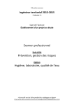
Figure 1 shows the customized Z8 Encore! XP F1680 Series board and Universal PCB.
Figure 1. The Customized Z8 Encore! XP F1680 Series Board and Universal PCB
Normal Mode
The F1680 Series MCU operates in default MCU configuration; the peripheral blocks are
enabled except for a low-power operational amplifier which is disabled by default. For
default values and op amp configurations, please see Zilog’s companion document, the Z8
Encore! XP F1680 Series Product Specification (PS0250).
Program RAM
The Z8 Encore! XP F1680 Series devices contain up to 1 KB of on-chip Program RAM.
This Program RAM is mapped in the Program Memory address space beyond the on-chip
Flash memory. It is entirely under user control and is meant to store the interrupt service
routines of high-frequency interrupts. Because interrupts bring the CPU out of low-power
AN031302-0511
Page 2 of 16
Enabling Low Power Modes with the Z8 Encore! XP F1680 Series MCU
Application Note
mode, it is important to ensure that interrupts that occur very often use as low a current as
possible. Program RAM-based handling of high-frequency interrupts provides power savings by keeping the Flash block disabled. It is optimized for low-current operation and can
be easily boot-strapped with interrupt code at power-up.
Power Control Register
Each bit in the register listed in Table 1 disables a peripheral block by removing power
from the block; the default state of the low-power operational amplifier is OFF. To use the
low-power operational amplifier, clear the TRAM bit by turning it ON1. The TRAM bit
enables the amplifier in STOP Mode; if the amplifier is not required in STOP Mode, disable it. Failure of the op amp to perform could result in STOP Mode currents greater than
specified.
Caution: Clearing the TRAM bit could interfere with normal ADC measurements on the LPO output, ANA0.
Table 1. Power Control Register 0 (PWRCTL0)
Bits
7
Field
TRAM
Reset
R/W
6
5
4
3
2
1
0
Reserved
LVD/VBO
TEMP
Reserved
COMP0
COMP1
1
0
0
0
0
0
0
R/W
R/W
R/W
R/W
R/W
R/W
R/W
ADDR
F80H
Bit
Description
7
TRAM
0 = Low-Power Operational Amplifier is enabled; also applicable to STOP Mode.
1 = Low-Power Operational Amplifier is disabled.
6:5
Reserved.
4
LVD/VBO (Low-Voltage Detection/Voltage Brownout Detector Disable)
0 = LVD/VBO Enabled
1 = LVD/VBO Disabled. The LVD and VBO circuits are enabled or disabled separately to
minimize power consumption in low-power modes. The LVD is controlled only by the LVD/VBO
bit in all modes. The VBO is set by the LVD/VBO bit as well as the VBO_AO bit of Flash Option
bits at Program Memory Address 0000H.
3
TEMP (Temperature Sensor Disable)
0 = Temperature Sensor Enabled.
1 = Temperature Sensor Disabled.
2
Reserved.
1. If peripherals are not in use, the user can turn off the peripheral bit in all modes to reduce power consumption.
AN031302-0511
Page 3 of 16
Enabling Low Power Modes with the Z8 Encore! XP F1680 Series MCU
Application Note
1
COMP0 (Comparator 0 Disable)
0 = Comparator 0 is Enabled; also applicable to STOP Mode.
1 = Comparator 0 is Disabled.
0
COMP1 (Comparator 1 Disable)
0 = Comparator 1 is Enabled; also applicable to STOP Mode.
1 = Comparator 1 is Disabled.
HALT Mode
Executing the HALT instruction places the device into HALT mode, which manifests the
following operating characteristics:
•
The primary oscillator is enabled and continues to operate
•
The system clock is enabled and continues to operate
•
The program counter (PC) stops incrementing
•
If enabled, the internal RC oscillator of the WDT continues to operate
•
If enabled, the WDT continues to operate
•
If enabled, the 32 kHz secondary oscillator for Timers continues to operate
•
All other on-chip peripherals continue to operate
The eZ8 CPU can be brought out of HALT mode by any of the following operations:
•
Timer timeout (Interrupt or Reset)
•
Interrupt (if enabled)
•
Watchdog
•
Power-On Reset
•
Voltage Brownout Reset
•
External RESET pin assertion
Note: You can place the device into HALT mode if the system does not have a process to execute; however, the peripherals can continue to operate and wait for an interrupt to bring
them out of HALT mode.
STOP Mode
Executing the eZ8 CPU’s STOP instruction places the device into STOP Mode. In STOP
Mode, the operating characteristics are:
AN031302-0511
Page 4 of 16
Enabling Low Power Modes with the Z8 Encore! XP F1680 Series MCU
Application Note
•
The primary crystal oscillator and the internal precision oscillator are stopped. XIN
and XOUT, if previously enabled, are disabled; and if previously enabled for port
function, PA0/PA1 reverts to the states programmed by the GPIO registers.
•
The system clock is stopped.
•
The eZ8 CPU is stopped.
•
The program counter (PC) stops incrementing.
•
The Watchdog Timer’s internal RC oscillator continues operating if enabled by the
Oscillator Control Register.
•
If enabled, the Watchdog Timer (WDT) logic continues operating.
•
If enabled, the 32 kHz secondary oscillator continues operating.
•
If enabled for operation in STOP Mode, the Timer logic continues to operate with a
32 kHz secondary oscillator as the Timer clock source.
•
If enabled for operation in STOP Mode by the associated Flash Option Bit, the VBO
protection circuit continues operating. The low-voltage detection circuit continues to
operate if it is enabled by the Power Control Register.
•
The Low-Power Operational Amplifier and comparator continue to operate if they are
enabled by the Power Control Register.
•
All other on-chip peripherals are idle and powered down.
When the device is in STOP Mode, a Stop Mode Recovery is initiated by each of the following:
•
A Watchdog Timer time-out
•
A GPIO Port input pin transition on an enabled Stop Mode Recovery source
•
An interrupt from a timer or comparator enabled for STOP Mode operation
The low-voltage detection circuitry on the F1680 device features the following:
•
The low-voltage detection threshold level is user-defined
•
The device generates an interrupt when the supply voltage drops below a user-defined
level
Note: If the system does not have a process to execute, the eZ8 CPU should be placed into STOP
Mode and await any transition in the Stop Mode Recovery assignment pin to bring it out
of STOP Mode.
AN031302-0511
Page 5 of 16
Enabling Low Power Modes with the Z8 Encore! XP F1680 Series MCU
Application Note
Table 2. Current and Power Consumption in NORMAL, HALT and STOP Modes
Mode
Current
Consumption
(mA)
Power (mW) Condition (3.0 V)
5.792
17.376
FSYSCLK = 11.0592 MHz IPO, PRAM = D; all peripherals
enabled.
5.783
17.349
FSYSCLK = 11.0592 MHz IPO, PRAM = D, LPOA disabled; all
other peripherals enabled.
5.772
17.316
FSYSCLK = 11.0592 MHz IPO, PRAM = D; LVD/VBO disabled,
all other peripherals enabled.
5.737
17.211
FSYSCLK = 11.0592 MHz IPO, PRAM = D; Temperature
Sensor disabled, all other peripherals enabled.
5.604
16.812
FSYSCLK = 11.0592 MHz IPO, PRAM = D; Comparator
disabled, all other peripherals enabled.
5.542
16.626
FSYSCLK = 11.0592 MHz IPO, PRAM = D; all peripherals
disabled.
3.628
10.884
FSYSCLK = 11.0592 MHz IPO, PRAM = E; all peripherals
enabled.
3.621
10.863
FSYSCLK = 11.0592 MHz IPO, PRAM = E; LPOA disabled, all
other peripherals enabled.
3.607
NORMAL
Execution
from PRAM 3.581
10.821
FSYSCLK = 11.0592 MHz IPO, PRAM = E; LVD/VBO disabled,
all other peripherals enabled.
10.743
FSYSCLK = 11.0592 MHz IPO, PRAM = E; Temperature
Sensor disabled, all other peripherals enabled.
3.462
10.386
FSYSCLK = 11.0592 MHz IPO, PRAM = E; Comparator
disabled, all other peripherals enabled.
3.406
10.218
FSYSCLK = 11.0592 MHz IPO, PRAM = E; all peripherals
disabled.
NORMAL
Execution
from Flash
Notes:
• The term peripherals refers to the Op Amps, LVD/VBD, Temp Sensor, Comp 0 and Comp 1.
• Measurements are not in cumulative order, but instead are individual measurements in condition and mode.
• The values in this table were measured using a microammeter. To determine more exact values, use a nanoammeter.
AN031302-0511
Page 6 of 16
Enabling Low Power Modes with the Z8 Encore! XP F1680 Series MCU
Application Note
Table 2. Current and Power Consumption in NORMAL, HALT and STOP Modes (Continued)
Mode
HALT
STOP
Current
Consumption
(mA)
Power (mW) Condition (3.0 V)
2.667
8.001
FSYSCLK = 11.0592 MHz IPO; all peripherals enabled
including VBO, WDT, T0 and T1.
2.421
7.264
FSYSCLK = 11.0592 MHz IPO; WDT, T0 and T1 enabled, all
other peripherals disabled.
2.419
7.257
FSYSCLK = 11.0592 MHz IPO; T0 and T1 enabled, all other
peripherals disabled.
2.367
7.101
FSYSCLK = 11.0592 MHz IPO; WDT enabled, all other
peripherals disabled.
2.365
7.095
FSYSCLK = 11.0592 MHz IPO; all peripherals disabled.
0.006
0.018
WDT, T0 and T1 enabled; all other peripherals disabled.
0.004
0.012
T0 and T1 enabled; all other peripherals disabled.
0.002
0.006
WDT enabled; all other peripherals disabled.
< 0.001
< 0.003
All peripherals disabled.
Notes:
• The term peripherals refers to the Op Amps, LVD/VBD, Temp Sensor, Comp 0 and Comp 1.
• Measurements are not in cumulative order, but instead are individual measurements in condition and mode.
• The values in this table were measured using a microammeter. To determine more exact values, use a nanoammeter.
Hardware Architecture
To minimize power consumption when the system is not in use, the F1680 MCU is
equipped with a low power modes option with which the user can place the MCU into
STOP and HALT modes. The capability to control peripherals can add further power savings. The Power Control Register allows the user to disable or enable power in unused
peripherals for additional power reduction. For a visual representation of the op amp,
LVD, VBO, temperature sensor, comparators and peripherals that the Power Control Register can control, see the architectural diagram in Appendix A on page 13.
Software Implementation
The reference design discussed in this application note uses ZDS II v4.11.0 and the Z8
Encore! XP F1680 Development Kit to simulate the STOP and HALT low-power modes,
while controlling the peripherals with the Power Control Register. In this design, the
objective is to implement these low-power modes using the blinker program.
First, configure the LVD/VBO to be OFF during STOP and HALT modes. The following
code segment demonstrates a placement of the value 0xF7 into Flash Option Register 1 to
turn off VBO in Stop Mode; the PRAM is used as Program RAM.
#include <ez8.h>
AN031302-0511
Page 7 of 16
Enabling Low Power Modes with the Z8 Encore! XP F1680 Series MCU
Application Note
FLASH_OPTION1 = 0xF7; //VBO_AO=OFF; PRAM=Enabled
FLASH_OPTION2 = 0xFF; //Default user flash option2
Next, use the IPO by placing 0xC0 into OSCCTL1 to serve as the clock source, as follows:
OSCCTL0 = 0x8A0; //Use Internal Clock F=11.0592 MHZ
OSCCTL1 = 0xC0; // use IPO to Drive System Clock
Disable the Timers if they are not required in your design and instead use the peripheral
timer clock source. ADC and I2C can also be disabled to reduce power consumption by
setting ADCCTL0 = 0x00 and I2CCTL = 0x00. The control registers that govern the
other peripherals can be used to attain additional power savings, and power in the peripheral block can be disabled via the Power Control Register, as shown below.
PWRCTL0 = 0xFF; //TRAM; LVD/VBO; TEMP; COMP0; COMP1 are turned off
Setting or clearing each bit of the Power Control Register enables or disables power in the
peripheral block. PWRCTL0 can be initialized in any part of the source code.
To execute in Program RAM (PRAM) during NORMAL Mode, the determination was to
insert the #pragma PRAM statement above the void main(void) statement, as
shown:
#pragma PRAM
Void main(void)
{
.
.
.
}
Example 1 below turns the LED ON and OFF in PORT C and goes into STOP/HALT
mode after 50 cycles.
Example 1. Blinker Program with STOP Mode
for(x=0;x<100;x++) {
for(i=0;i<0xFFFF;i++);
PCOUT = ~PCOUT;
}
PCOUT =~0x00;
asm("STOP");
while(1);
AN031302-0511
Page 8 of 16
Enabling Low Power Modes with the Z8 Encore! XP F1680 Series MCU
Application Note
The asm("STOP") command places the device into STOP Mode. The device can be
brought out of STOP Mode by means of a Stop Mode Recovery. Configure this Stop
Mode Recovery by tying the GPIO interrupt at pin PA2. Any logic transition at pin PA2
can bring the device out of STOP Mode, as shown by the following code and Figure 2.
PADD = 0x04;
PAAF = 0x00;
PAOC = 0x00;
PAHDE = 0x00;
PAPUE = 0x04;
PASMRE = 0x04;
Figure 2. Recovery from STOP Mode at Pin PA2
The Blinker program used in Example 1 can also be used to place the F1680 device into
HALT mode, as shown in Example 2.
Example 2. Blinker Program with HALT mode
for(x=0;x<100;x++) {
for(i=0;i<0xFFFF;i++);
PCOUT = ~PCOUT;
}
PCOUT =~0x00;
asm("HALT");
while(1);
The asm("HALT") command places the device into HALT mode. The device can be
brought out of HALT Mode by a reset or a Stop Mode Recovery and by using a RESET
assertion, as shown in Figure 3.
AN031302-0511
Page 9 of 16
Enabling Low Power Modes with the Z8 Encore! XP F1680 Series MCU
Application Note
Figure 3. Recovery from HALT Mode
To review the entire codeset for the with low power mode Blinker program, see Appendix
B on page 14.
Required Equipment
The equipment listed below is used to build the Blinker application.
1. F1680 Series Development Kit featuring the F1680 MCU
2. ZDS II Z8 Encore 4.11.0
3. Multimeter
4. Power Supply
Setup
Figures 4 and 5 show a simple block diagram and an actual image of the Blinker application setup.
Figure 4. Blinker Application Setup, Block Diagram
AN031302-0511
Page 10 of 16
Enabling Low Power Modes with the Z8 Encore! XP F1680 Series MCU
Application Note
Figure 5. Blinker Application Setup, Actual
Results
Each mode of operation results in a significant reduction in power consumption. See Table
2 on page 6 for the measurement results showing current and power usage under different
modes and conditions.
Summary
This application note provides a blueprint for utilizing the low power features of the Z8
Encore! XP F1680 Series MCU. A simple hardware architecture and a simple Blinker program enable different low power mode possibilities. The Blinker software is modular and
easy to customize for any low power application.
AN031302-0511
Page 11 of 16
Enabling Low Power Modes with the Z8 Encore! XP F1680 Series MCU
Application Note
References
The following documents associated with the Z8 Encore! XP F1680 device are available
on www.zilog.com.
•
Z8 Encore! XP F1680 Series Product Specification (PS0250)
•
Z8 Encore! XP F1680 28-pin Development Kit User Manual (UM0203)
AN031302-0511
Page 12 of 16
Enabling Low Power Modes with the Z8 Encore! XP F1680 Series MCU
Application Note
Appendix A. Z8 Encore! XP F1680 Block Diagram
Figure 7 shows the architecture of the Z8 Encore! XP F1680 MCU, complete with peripheral blocks.
Figure 6. Z8 Encore! XP F1680 Block Diagram
AN031302-0511
Page 13 of 16
Enabling Low Power Modes with the Z8 Encore! XP F1680 Series MCU
Application Note
Appendix B. Low Power Modes Source Code
//LED at PORTC Blinker Program with Low Power Modes
/
******************************************************************
* This is compiled using ZDSII Z8 Encore 4.11.0
* Copyright (C) 1999-2008 by Zilog, Inc. ALL RIGHTS RESERVED.
* The source code in this file was written by an authorized
* Zilog employee or a licensed consultant. The source code has
* been verified to the fullest extent possible.Permission to
* use this code is granted on a royalty-free basis. However
* users are cautioned to authenticate the code contained herein.
* Zilog DOES NOT GUARANTEE THE VERACITY OF THE SOFTWARE.
******************************************************************
/
#include <ez8.h>
FLASH_OPTION1 = 0xF7;
FLASH_OPTION2 = 0xFF;
#pragma PRAM
void main (void)
//WDT ON |T0 & T1 enable &
//Everything OFF, Running on Stop Mode
{
unsigned int delay = 5000;
unsigned int x, i;
DI();
// WDTH = 0x55;
//WDT Unlock Sequence
// WDTH = 0xAA;
// WDTH = 0xFF;
//WDT Timer
// WDTL = 0xFF;
//Max = 0xFFFF (6.55 sec)
LEDEN = 0x00;
LEDLVLH = 0x00;
LEDLVLL = 0x00;
PADD = 0x04;
//PA as Output MODE
PAAF = 0x00;
PAOC = 0x00;
PAHDE = 0x00;
PAPUE = 0x00;
PASMRE = 0x00;
// PASMRE = 0x040; //Any logic transition on this port during STOP mode initiates Stop
//Mode Recovery. For HALT mode, Reset assertion initiate recovery
PAOUT =0xFF;
//PA Data FFH
PBDD= 0x00;
//PB as Output MODE
PBAF = 0x00;
PBOC = 0x00;
PBHDE = 0x00;
PBPUE = 0x00;
PBSMRE = 0x00;
PBOUT =0xFF;
//PB Data FFH
AN031302-0511
Page 14 of 16
Enabling Low Power Modes with the Z8 Encore! XP F1680 Series MCU
Application Note
PCDD = 0x00;
//PC as Output MODE
PCAF = 0x00;
PCOC = 0x00;
PCPUE = 0x00;
PCHDE = 0x00;
PCSMRE = 0x00;
PCOUT = 0xFF;
//PC Data FFH
OSCCTL0 = 0xE7; //Unlock sequence
OSCCTL0 = 0x18;
OSCCTL0 = 0x80;
// OSCCTL0 = 0x80|0x20;
while(delay--);
OSCCTL1 = 0xE7;
OSCCTL1 = 0x18;
OSCCTL1 = 0xC0; //use IPO to Drive System Clock
// PWRCTL0 = 0x00; //LPO, VBO, TEMP, COMP are enabled
PWRCTL0 = 0x9B; //LPO, VBO, TEMP, COMP are disabled
T0CTL0
T1CTL0
T0CTL1
T1CTL1
T0CTL2
T1CTL2
T0CTL1
T1CTL1
EI();
//
//
= 0x00; //Set up T0 & T1 Timers
= 0x00; //Driven by external 32Khz CRYSTAL
= 0x39;
= 0x39;
= 0x00;
= 0x00;
|= 0x80;
|= 0x80;
for(x=0;x<100;x++) {
for(i=0;i<0xFFFF;i++);
PCOUT = ~PCOUT;
PAOUT = ~PAOUT;
}
asm("WDT");
asm("STOP"); //Put the device
//Uncomment this
asm("HALT"); //Put the device
//Uncomment this
while(1);
in STOP mode
for STOP mode
in HALT mode
for HALT mode
}
AN031302-0511
Page 15 of 16
Enabling Low Power Modes with the Z8 Encore! XP F1680 Series MCU
Application Note
Customer Support
To share comments, get your technical questions answered, or report issues you may be
experiencing with our products, please visit Zilog’s Technical Support page at
http://support.zilog.com.
To learn more about this product, find additional documentation, or to discover other facets about Zilog product offerings, please visit the Zilog Knowledge Base at http://
zilog.com/kb or consider participating in the Zilog Forum at http://zilog.com/forum.
This publication is subject to replacement by a later edition. To determine whether a later
edition exists, please visit the Zilog website at http://www.zilog.com.
Warning: DO NOT USE THIS PRODUCT IN LIFE SUPPORT SYSTEMS.
LIFE SUPPORT POLICY
ZILOG’S PRODUCTS ARE NOT AUTHORIZED FOR USE AS CRITICAL COMPONENTS IN LIFE
SUPPORT DEVICES OR SYSTEMS WITHOUT THE EXPRESS PRIOR WRITTEN APPROVAL OF
THE PRESIDENT AND GENERAL COUNSEL OF ZILOG CORPORATION.
As used herein
Life support devices or systems are devices which (a) are intended for surgical implant into the body, or (b)
support or sustain life and whose failure to perform when properly used in accordance with instructions for
use provided in the labeling can be reasonably expected to result in a significant injury to the user. A
critical component is any component in a life support device or system whose failure to perform can be
reasonably expected to cause the failure of the life support device or system or to affect its safety or
effectiveness.
Document Disclaimer
©2011 Zilog, Inc. All rights reserved. Information in this publication concerning the devices, applications,
or technology described is intended to suggest possible uses and may be superseded. ZILOG, INC. DOES
NOT ASSUME LIABILITY FOR OR PROVIDE A REPRESENTATION OF ACCURACY OF THE
INFORMATION, DEVICES, OR TECHNOLOGY DESCRIBED IN THIS DOCUMENT. ZILOG ALSO
DOES NOT ASSUME LIABILITY FOR INTELLECTUAL PROPERTY INFRINGEMENT RELATED
IN ANY MANNER TO USE OF INFORMATION, DEVICES, OR TECHNOLOGY DESCRIBED
HEREIN OR OTHERWISE. The information contained within this document has been verified according
to the general principles of electrical and mechanical engineering.
Z8, Z8 Encore!, Z8 Encore! XP and ZMOTION are trademarks or registered trademarks of Zilog, Inc. All
other product or service names are the property of their respective owners.
AN031302-0511
Page 16 of 16