1
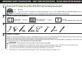
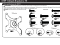
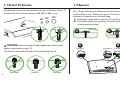
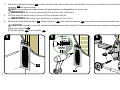
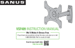
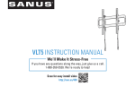
VSF415 INSTRUCTION MANUAL
We’ll Make It Stress-Free
If you have any questions along the way, just give us a call.
1-800-359-5520. We’re ready to help!
Scan for easy install video
http://san.us/403
IMPORTANT SAFETY INSTRUCTIONS – SAVE THESE INSTRUCTIONS – PLEASE READ ENTIRE MANUAL PRIOR TO USE
Before getting started, let’s make sure this mount is perfect for you!
1
2
Does your TV weigh more than 50 lb (22.7 kg) including accessories?
50 lb No — Perfect!
(22.7 kg) Yes — This mount is NOT compatible. Visit MountFinder.Sanus.com or call 1-800-359-5520 (UK: 0800-056-2853) to find a compatible mount.
NOTE: The VSF415 adjustable arm wall mount is designed to be used with the LR1A in-wall mount.
What is your wall made of?
Drywall with
Perfect!
wood studs
3
Unsure?
Call 1-800-359-5520 (UK: 0800-056-2853)
Do you have all of the tools needed?
7/32 in.
(5.5 mm)
Wood
4
?
Solid concrete or Perfect!
concrete block
3/8 in.
(10 mm)
Concrete
1/2 in.
(13 mm)
Ready to begin?
Please read through these instructions completely to be sure you’re comfortable with this easy install process. Also check your TV
owner’s manual to see if there are any special requirements for mounting your TV.
If you do not understand these instructions or have doubts about the safety of the installation, assembly or use of this product, contact
Customer Service at 1-800-359-5520 (UK: 0800-056-2853).
CAUTION: Avoid potential personal injuries and property damage!
2
●
●
●
●
This product is designed for use in wood stud, solid concrete, and concrete block walls - DO NOT install into drywall alone
The wall must be capable of supporting five times the weight of the TV and mount combined
Do not use this product for any purpose not explicitly specified by manufacturer
Manufacturer is not responsible for damage or injury caused by incorrect assembly or use
STEP 1 Attach Bracket to TV
Parts and Hardware for STEP 1
WARNING: This product contains small items that could be a choking hazard if swallowed.
Before starting assembly, verify all parts are included and undamaged. If any parts are missing or damaged, do not return the damaged
item to your dealer; contact Customer Service. Never use damaged parts!
TV Screws
NOTE: Not all hardware included will be used.
M4 x 12mm
M4 x 30mm
02 x4
TV Bracket
M6 x 12mm
04 x4
03 x4
M6 x 20mm
M6 x 35mm
05 x4
06 x4
M8 x 20mm
M8 x 12mm
M8 x 35mm
08 x4
07 x4
09 x4
TV Washers
TV Spacers
01 x1
10 x8
11 x4
M4
M6/M8
12 x4
M4
13 x4
M6/M8
3
1-1 Select TV Screws
1-2 Spacers
Hand thread screws into the threaded inserts on the back of your TV
to determine which screw diameter (M4, M6, or M8) to use.
M4 M6
M8
Your TV type will help you determine which hardware
configuration to use. Match your type of TV to the suggested
hardware configuration on the next page.
A. Installation option without spacers (TVs with flat backs).
B. Installation option using spacers (TVs with obstructed backs
or inset mounting holes).
TV Bracket
06
A
B
TV Bracket
TV Bracket
CAUTION: Verify adequate thread engagement of the screw/
spacer combination on your TV.
Too short will not hold the TV and too long will damage the TV.
4
Too Short
Correct
Too Long
A
Flat Back
B
Round Back
Inset Holes
Cables
1-3 Attach TV Bracket
Position the TV bracket 01 over your TV hole pattern and install using the screw, washer, and spacer (if needed) combination you selected for
your TV.
M4/M6/M8 screw and washer
02 04 05 07 08
10 11
M4 spacer, screw, and washers
12
10
10
03
01
M6/M8 spacer, screw, and washer
11
06 09
13
5
STEP 2 Attach Wall Plate to Wall
For wood stud installations, follow STEP 2A on PAGE 7
For concrete installations, follow STEP 2B on PAGE 9
Parts and Hardware for STEP 2
WARNING: This product contains small items that could be a choking hazard if swallowed.
Before starting assembly, verify all parts are included and undamaged. If any parts are missing or damaged, do not return the damaged
item to your dealer; contact Customer Service. Never use damaged parts!
Sanus Magnetic Stud Finder
NOTE: Not all hardware included will be used.
Wall Plate
Template
Arm Assembly/Wall Plate
Lag Bolts
5/16 x 2 ¾ in.
15 x1
14 x1
6
16 x1
Lag Bolt Washers
17 x2
Concrete Anchors
19 x2
Covers
20 x2
18 x2
STEP 2A
Wood Stud Option
CAUTION: Avoid potential personal injuries and
property damage!
●
●
●
1
Max. 16 mm
(5/8 in.)
Drywall covering the wall must not exceed
16 mm (5/8 in.)
Minimum wood stud size: common 51 x 102 mm (2 x 4 in.)
nominal 38 x 89 mm (1½ x 3½ in.)
Stud center must be verified
NOTE: See Introducing Sanus Magnetic Stud Finder*
located in your Welcome folder for more detailed
operation of stud finder.
1.
Locate a nail/screw in the stud using the Sanus magnetic
stud finder 16 provided.
2.
Find the edges of the stud using the probe
of the stud finder 16 .
3.
Mark the center of the stud with pencil.
Min. 89 mm
(3 1/2 in.)
Min. 38 mm
(1 1/2 in.)
2
16
3
* WARNING: This product contains a magnet. If an implanted medical device such as a pacemaker or implantable cardioverter defibrillator (ICD)
is in use, magnetic fields may affect the operation of those devices, resulting in serious injury or death. If you have an implanted medical device, keep at
least 13 cm (5 in.) between your device and the magnet. Please consult with your physician or medical professional prior to using this product.
7
Place the wall plate template 14 at your desired height and position the slotted holes over your stud center line. Level the wall plate
template 14 and tape in place.
NOTE: For assistance in determining wall plate location, see HeightFinder at sanus.com.
IMPORTANT: Be sure you mark and drill into the center of the stud.
Drill the two pilot holes using a 5.5 mm (7/32 in.) diameter drill bit.
IMPORTANT: Pilot holes must be drilled to a depth of 75 mm (3 in.).
4.
5.
6.
Remove the wall plate template 14 . Tighten lag bolts 17 only until the washers 18 are pulled firmly against the wall plate 15 .
CAUTION: Improper use could reduce the holding power of the lag bolt. To avoid potential injuries or property damage Do not overtighten the lag bolts 17 .
Fit lag bolt covers 20 over lag bolts 17 .
4
5
6
75 mm
(3 in.)
5.5 mm
(7/32 in.)
17
14
15
20
14
8
18
STEP 2B
Solid Concrete or Concrete Block Option
CAUTION: Avoid potential personal injuries and property damage!
●
●
●
Mount the arm assembly/wall plate 15 directly onto the concrete surface
Minimum solid concrete thickness: 203 mm (8 in.)
Minimum concrete block size: 203 x 203 x 406 mm (8 x 8 x 16 in.)
1.
Position the wall plate template 14 on the wall at your desired height. Level the wall plate template and mark the hole locations.
NOTE: For assistance in determining wall plate location, see Height Finder at sanus.com.
2.
Drill two pilot holes using a 10 mm (3/8 in.) diameter drill bit.
IMPORTANT: Pilot holes must be drilled to a depth of 75 mm (3 in.). Never drill into the mortar between blocks.
Remove the wall plate template 14 and insert two anchors 19 .
3.
CAUTION: Be sure the anchors
1
19 are seated flush with the concrete surface.
2
75 mm
(3 in.)
10 mm
(3/8 in.)
3
19
14
14
9
Remove the wall plate template 14 . Tighten lag bolts 17 only until the washers 18 are pulled firmly against the wall plate 15 .
CAUTION: Improper use could reduce the holding power of the lag bolt. To avoid potential injuries or property damage Do not over-
4.
tighten the lag bolts 17 .
Fit lag bolt covers 20 over lag bolts 17 .
5.
5
4
15
18
15
17
20
10
STEP 3 Hang TV Mount to Arm
Parts and Hardware for STEP 3
WARNING: This product contains small items that could be a choking hazard if swallowed.
Before starting assembly, verify all parts are included and undamaged. If any parts are missing or damaged, do not return the damaged
item to your dealer; contact Customer Service. Never use damaged parts!
Cover
Pivot Pin
20 x2
Large Washer
21 x1
Mounting Bolt Nut
23 x1
22 x1
Spacer
Mounting Bolt
¼-20 x 3 ¼ in.
24 x1
5/32 in. Hex Key
25 x1
Washer
26 x2
27 x1
11
STEP 3 Hang TV Mount to Arm
1.
Fit nut 23 and cover 20 into underside of mount arm 15 .
2.
Place washer 22 and pivot pin 21 onto mount arm 15 .
3.
Fit the bracket 01 onto pivot pin 21 . Slide washers 26 and spacer 25 onto mounting bolt 24 and fit bolt through mounting bracket
01 and pivot pin 21 until it meets nut 23 . Fit cover 20 over mounting bolt.
HEAVY! You may need assistance with this step.
Use hex key 27 to tighten mounting bolt 24 and secure mounting bracket to arm.
4.
NOTE: You may need to hold the mounting nut 23 in place as you are tightening the bolt 24 .
1
2
15
3
21
01
22
23
20
24
26
25
26
15
4
27
24
01
15
20
15
12
Adjustments
A. Use hex key 27 to adjust arm extension tension.
B. Adjust left/right/rotation swivel tension.
B
A
27
15
13
Manage Cables
Parts and Hardware for Manage Cables
WARNING: This product contains small items that could be a choking hazard if swallowed.
Before starting assembly, verify all parts are included and undamaged. If any parts are missing or damaged, do not return the damaged
item to your dealer; contact Customer Service. Never use damaged parts!
Cable Plate
Cable Plate Screws
8-32 x 0.5 in.
8-32 x ½ in.
29 x4
28 x2
Cable Ties
30 x4
14
Manage Cables
Option A:
Thread cable through channels the secure with plates 28 and plate screws 29 .
Option B:
Install plates 28 with plate screws 29 . Thread cable ties 30 through end holes in plates 28 . Arrange cables then secure them with the
cable ties 30 .
NOTE: Pull the arm to its full extension before routing the cables through the channels, then loosely route the cables. This will give the cables
enough slack to prevent excess tension when adjusting the position of the arm.
A
B
28
OR
29
28
30
29
30
15
Dimensions
200 mm
(7.87 in.)
100 mm
(3.94 in.)
75 mm
(2.95 in.)
384.3 mm
(15.13 in.)
360°
75 mm
(2.95 in.)
100 mm 200 mm
(3.94 in.) (7.87 in.)
237.7 mm
(9.36 in.)
162.6 mm
(6.40 in.)
±15°
249.2 mm
(9.81 in.)
231.65 mm
(9.12 in.)
282.45 mm
(11.12 in.)
171.5 mm
(6.75 in.)
59.18 mm
(2.33 in.)
360°
180°
78.7 mm
(3.1 in.)
152.4 mm
(6.0 in.)
±15°
16
300.5 mm
(11.83 in.)
17
INSTRUCCIONES IMPORTANTES DE SEGURIDAD. GUARDE ESTAS INSTRUCCIONES.
LEA TODO EL MANUAL ANTES DE UTILIZAR ESTE PRODUCTO.
ESPAÑOL
Antes de empezar, asegurémonos de que este soporte es perfecto para usted.
1
¿Su televisor pesa más de 22,7 kg (50 lb) incluidos los accesorios?
2
¿De qué material es su pared?
3
22,7 kg
(50 lb)
No — ¡Perfecto!
Sí — Este soporte NO es compatible. Visite MountFinder.Sanus.com o llame al número 1-800-359-5520 (Reino Unido: 0800-056-2853)
para encontrar un soporte compatible.
Mampostería con
montantes de madera
Hormigón macizo o
bloque de hormigón
¡Perfecto!
¡Perfecto!
¿No está seguro?
Llame al número 1-800-359-5520 (Reino Unido: 0800-056-2853)
¿Tiene todas las herramientas necesarias?
7/32"
(5,5 mm)
Madera
4
?
3/8"
(10 mm)
Hormigón
1/2"
(13 mm)
¿Está listo para empezar?
Lea completamente estas instrucciones para asegurarse de comprender bien este sencillo proceso de instalación. Compruebe también
el manual del propietario de su televisor para comprobar si hay algún requisito especial para montar su televisor.
Si no entiende las instrucciones o si tiene dudas acerca de la seguridad de la instalación, el montaje o el uso del producto, póngase en
contacto con el servicio de atención al cliente en el número 1-800-359-5520 (Reino Unido: 0800-056-2853).
18
ESPAÑOL
PASO 1 Coloque el soporte en el televisor
Piezas y elementos de sujeción para el PASO 1
ADVERTENCIA: Este producto contiene piezas pequeñas que podrían causar asfixia si fuesen tragadas.
Antes de comenzar a montar la unidad, verifique que todas las piezas estén incluidas y en buen estado.
En caso de que falten piezas o alguna esté dañada, no devuelva el elemento defectuoso al distribuidor.
Póngase en contacto con el servicio de atención al cliente. Nunca utilice piezas en mal estado.
1-1 Seleccione los tornillos del televisor
Enrosque manualmente los tornillos en los orificios roscados de la
parte posterior del televisor para determinar el diámetro correcto
de los tornillos (M4, M6 o M8) que se deben utilizar.
PRECAUCIÓN: Verifique que la combinación de tornillo/
espaciador es correcta en el televisor.
Si el tornillo es demasiado corto no sujetará el televisor y si es
demasiado largo dañará el televisor.
NOTA: No se utilizarán
todos los elementos de
sujeción incluidos.
1-2 Espaciadores
El tipo de televisor le ayudará a determinar la configuración
de elementos de sujeción que debe utilizar. Compruebe la
configuración de elementos de sujeción recomendada para
su tipo de televisor en la página siguiente.
A. Opción de instalación sin espaciadores (televisores con parte
posterior plana).
B. Opción de instalación con espaciadores (televisores con
parte posterior obstruida u orificios de montaje empotrados).
1-3 Coloque el soporte del televisor
Coloque el soporte del televisor 01 sobre el patrón de orificios de su televisor e instálelo utilizando la combinación de tornillos, arandelas
y espaciadores (si son necesarios) que ha seleccionado para su televisor.
PASO 2 Coloque la placa de pared en la pared
Para instalaciones en montante de madera, siga el PASO 2A de la PÁGINA 7
Para instalaciones en hormigón, siga el PASO 2B de la PÁGINA 9
19
ESPAÑOL
Piezas y elementos de sujeción para el PASO 2
ADVERTENCIA: Este producto contiene piezas pequeñas que podrían causar asfixia si fuesen tragadas.
Antes de comenzar a montar la unidad, verifique que todas las piezas estén incluidas y en buen estado.
En caso de que falten piezas o alguna esté dañada, no devuelva el elemento defectuoso al distribuidor.
Póngase en contacto con el servicio de atención al cliente. Nunca utilice piezas en mal estado.
PASO 2A
NOTA: No se utilizarán
todos los elementos de
sujeción incluidos.
Opción de montante de madera
PRECAUCIÓN: Evite posibles lesiones físicas y daños materiales.
●
●
●
La mampostería que cubre la pared no debe superar los 16 mm (5/8")
Tamaño mínimo del montante de madera: común 51 x 102 mm (2" x 4") nominal 38 x 89 mm (11/2" x 31/2")
Debe verificarse el centro del montante
NOTA: Consulte la Introducción al localizador de montantes magnético de Sanus* que encontrará en la carpeta de bienvenida si desea
información detallada sobre el funcionamiento del localizador de montantes.
1.
2.
3.
4.
Localice un clavo/tornillo del montante utilizando el localizador de montantes magnético de Sanus 16 suministrado.
Localice los bordes del montante utilizando la sonda del localizador de montantes 16 .
Marque el centro del montante con un lápiz.
Coloque la plantilla de la placa de pared 14 a la altura que desee y posicione los orificios perforados sobre la línea central del montante.
Nivele la plantilla de la placa de pared 14 y péguela con cinta adhesiva en su posición.
*
ADVERTENCIA: Este producto contiene un imán. Si está utilizando un dispositivo médico implantado como un marcapasos o un
desfibrilador cardioversor implantable (DCI), los campos magnéticos pueden afectar al funcionamiento de esos dispositivos y producir lesiones
graves o la muerte. Si tiene un dispositivo médico implantado, mantenga una distancia mínima de 13 cm (5") entre su dispositivo y el imán.
Consulte con un médico o un profesional sanitario antes de utilizar este producto.
20
ESPAÑOL
5.
6.
NOTA: Si necesita ayuda para determinar la posición de la placa de pared, consulte Height Finder en sanus.com.
IMPORTANTE: Asegúrese de hacer las marcas y taladrar en el centro del montante.
Taladre los dos orificios guía utilizando una broca de 5,5 mm (7/32") de diámetro.
IMPORTANTE: Los orificios guía deben taladrarse hasta una profundidad de 75 mm (3").
Retire la plantilla de la placa de pared 14 . Apriete los pernos tirafondo 17 solo hasta que las arandelas 18 queden firmemente sujetas
contra la placa de pared 15 .
PRECAUCIÓN: El uso incorrecto podría reducir la capacidad de sujeción del perno tirafondo. Para evitar posibles lesiones o daños
materiales, no apriete excesivamente los pernos tirafondo 17 .
Coloque las cubiertas 20 sobre los pernos tirafondo 17 .
PASO 2B
Opción de hormigón macizo o bloque de hormigón
PRECAUCIÓN: Evite posibles lesiones personales y daños materiales.
●
●
●
Monte el conjunto de brazo/placa de pared 15 directamente sobre la superficie de hormigón
Grosor mínimo del hormigón macizo: 203 mm (8")
Tamaño mínimo del bloque de hormigón: 203 x 203 x 406 mm (8 x 8 x 16")
1.
Coloque la plantilla de la placa de pared 14 sobre la pared a la altura deseada. Nivele la plantilla de la placa de pared y marque la posición
de los orificios.
NOTA: Si necesita ayuda para determinar la posición de la placa de pared, consulte Height Finder en sanus.com.
2.
Taladre los dos orificios guía utilizando una broca de 10 mm (3/8") de diámetro.
IMPORTANTE: Los orificios guía deben taladrarse hasta una profundidad de 75 mm (3"). Nunca taladre sobre el cemento entre los bloques.
3.
Retire la plantilla de la placa de pared 14 e inserte dos tacos 19 .
PRECAUCIÓN: Asegúrese de que los tacos
19 estén asentados al mismo nivel de la superficie de hormigón.
21
ESPAÑOL
4.
Retire la plantilla de la placa de pared 14 . Apriete los pernos tirafondo 17 solo hasta que las arandelas 18 queden firmemente sujetas
contra la placa de pared 15 .
PRECAUCIÓN: El uso incorrecto podría reducir la capacidad de sujeción del perno tirafondo. Para evitar posibles lesiones o daños
materiales, no apriete excesivamente los pernos tirafondo 17 .
5.
Coloque las cubiertas 20 sobre los pernos tirafondo 17 .
PASO 3 Cuelgue el soporte de televisor en el brazo
Piezas y elementos de sujeción para el PASO 3
ADVERTENCIA: Este producto contiene piezas pequeñas que podrían causar asfixia si fuesen tragadas.
Antes de comenzar a montar la unidad, verifique que todas las piezas estén incluidas y en buen estado. En caso de que falten piezas o alguna
esté dañada, no devuelva el elemento defectuoso al distribuidor. Póngase en contacto con el servicio de atención al cliente. Nunca utilice
piezas en mal estado.
1.
Coloque la tuerca 23 y la cubierta 20 en la parte inferior del brazo de montaje 15 .
2.
Coloque la arandela 22 y la clavija pivotante 21 sobre el brazo de montaje 15 .
3.
Ajuste el soporte 01 sobre la clavija pivotante 21 . Deslice las arandelas 26 y el espaciador 25 sobre el perno de montaje 24 y
pase el perno a través del soporte de montaje 01 y la clavija pivotante 21 hasta que se encuentre con la tuerca 23 . Coloque la
cubierta 20 sobre el perno de montaje.
PRECAUCIÓN: Necesitará ayuda para realizar esta operación.
4.
22
Utilice la llave hexagonal 27 para apretar el perno de montaje 24 y fije el soporte de montaje al brazo.
ESPAÑOL
Ajustes
A. Utilice la llave hexagonal 27 para ajustar la tensión de extensión del brazo.
B. Ajuste la tensión del giro a la izquierda/derecha.
Organización de cables
Piezas y elementos de sujeción para el PASO 3
ADVERTENCIA: Este producto contiene piezas pequeñas que podrían causar asfixia si fuesen tragadas.
Antes de comenzar a montar la unidad, verifique que todas las piezas estén incluidas y en buen estado.
En caso de que falten piezas o alguna esté dañada, no devuelva el elemento defectuoso al distribuidor.
Póngase en contacto con el servicio de atención al cliente. Nunca utilice piezas en mal estado.
NOTA: No se utilizarán
todos los elementos de
sujeción incluidos.
Opción A:
Enrosque el cable a través de los canales y fíjelo con las placas 28 y los tornillos de placa 29 .
Opción B:
Instale las placas 28 con los tornillos de placa 29 . Enrosque los sujetacables 30 a través de los orificios de los extremos de las placas 28 .
Organice los cables y fíjelos con los sujetacables 30 .
NOTA: Tire del brazo hasta su extensión máxima antes de pasar los cables a través de los canales y después dirija los cables sin una tensión
excesiva. De este modo los cables tendrán holgura suficiente para evitar un exceso de tensión al ajustar la posición del brazo.
Dimensiones
23
Thank you for choosing Sanus! Please take a moment to let us know how we did:
Call us: 1-800-359-5520
Email us: [email protected]
Leave a review: sanus.com
UK: 0800 056 2853
Milestone AV Technologies and its affiliated corporations and subsidiaries (collectively, “Milestone”), intend to make this manual accurate and complete. However,
Milestone makes no claim that the information contained herein covers all details, conditions, or variations. Nor does it provide for every possible contingency in
connection with the installation or use of this product. The information contained in this document is subject to change without notice or obligation of any kind.
Milestone makes no representation of warranty, expressed or implied, regarding the information contained herein. Milestone assumes no responsibility for accuracy,
completeness or sufficiency of the information contained in this document.
©2014 Milestone AV Technologies. All rights reserved. Sanus is a division of Milestone.
All other brand names or marks are used for identification purposes and are trademarks of their respective owners.
SANUS • 6436 City West Parkway • Eden Prairie, MN 55344 USA
6901-002255 01