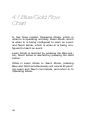
1
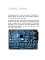
User’s Manual
Table of Contents
Getting Started
1
1 / What is OpenLCB?
3
Events
4
The Producer-Consumer Model
5
Railstars Io
6
Basic Terminology
7
2 / Connecting Io
8
Connecting to the OpenLCB Bus
8
Connecting Power
9
Io Inputs
12
Io Outputs
13
Connecting to Other Devices
14
3 / Configuring Io Using the Blue/
Gold Interface
15
1
The Blue/Gold Interface
16
Teaching and Learning
16
First Time Setup, and Hard Reset
17
Setting up Learning
18
Setting up Teaching
21
Example: Associating a Button with an
LED
24
Example: Duplicating a Fascia Panel Button
25
4 / Blue/Gold Flow Chart
2
28
Getting Started
Congratulations on your purchase of Railstars Io!
You’re layout will soon sit on the cutting edge of
model railroading technology.
Io (named for the Jovian moon, and pronounced
“EYE-oh”) is easy to install on new layouts, and
easy to integrate into existing layouts. This guide
will help you to connect Io, and to understand the
underlying technology so you can get the most
out of your purchase.
1
In Chapter 1, we introduce the basic concepts of
OpenLCB and the Producer-Consumer model, to
help you understand how Io works.
In Chapter 2, we show you how to connect Io to
you layout.
In Chapter 3, we show you how to configure your
Io boards to control your layout.
Check the Railstars website to find updated or
additional documents explaining how to connect
Io to a range of layout accessories you may already have installed, such as occupancy detectors and turnout controllers.
http://railstars.com
2
1 / What is OpenLCB?
OpenLCB is a new networking technology for
bringing all of your layout control elements together. What makes OpenLCB great is that it is
open, fast, and future-proof.
Open means that anyone can look at, implement,
or help to improve the standard without barriers of
any kind, so that hardware from different manufacturers will work together seamlessly.
Fast means that OpenLCB can keep up with
whatever is going on on your layout without bogging down under heavy loads.
Future-proof means that OpenLCB is not tied to
any particular technology, and can easily expand
and adapt to encompass whatever new technologies may come without leaving older technologies
behind. It also means that OpenLCB isn’t tied to
any current technology: You don’t have to be running DCC to take advantage of OpenLCB.
Working with OpenLCB requires understanding
few basic concepts that guide how it works,
namely: Events, and the Producer-Consumer
model.
3
Events
Events are the fundamental building blocks of an
OpenLCB network. An Event (with a capital ‘E’) is
an electronic representation of something interesting occurring on your layout. A button-press on a
fascia panel, a turnout changing position, a train
entering a new block: All of these occurrences
can be represented by Events on an OpenLCB
network.
Importantly, Events are not only generated when
something interesting happens, but also when
that interesting happening ends. For example, a
fascia-panel node will generate Events for button
presses, and also for button releases.
Each Event has a unique identifier, called the
EventID. An EventID permits nodes to distinguish
between different Events, and hence between different occurrences on the layout.
Crucially, OpenLCB Events do not have a preassigned meaning. That is, there is no intrinsic difference between, e.g., a button-press Event and a
block-occupancy Event. This is what makes
OpenLCB so powerful: You get to decide what
each Event means, and how it is to be used by
the various layout control elements on your layout.
Which brings us to the next key concept: How
Events are made and used.
4
The Producer-Consumer Model
There are two basic kinds of OpenLCB nodes:
Sensors that watch for specific occurrences on
your layout, called Producers, and nodes that take
some kind of action on your layout, called Consumers. Many OpenLCB nodes, such as Railstars
Io, will combine the functions of both Producer
and Consumer in one node.
The Producer-Consumer Model is a way of structuring a network. On this model, when a Producer
detects an interesting occurrence, it produces an
Event unique to that producer. Rather than being
delivered to a specific other node on the network,
the produced Event is broadcast to every node on
the network, allowing each node to decide
whether to act on that Event or not. A node that
acts on received Events is called a consumer.
This is the second element that makes OpenLCB
so powerful: Every Event is broadcast to every
node on the network. Thus, every consumer is
free to act on any Event, which allows a great deal
of flexibility in how Events can be interpreted and
used.
On this model, we can talk about Producers and
Consumers being connected by Events. By assigning the same EventID to a Producer and a
Consumer, the Consumer will respond to the
Events produced by that Producer, connecting the
5
two. Typically, each Producer and each Consumer
can be assigned exactly one EventID.
To give an example, let us suppose that a train
enters a new block. A block-occupancy node detects the train, and produces an Event in response. A node powering a fascia panel might interpret that Event as a command to light an occupancy indicator on the panel. A signal tower node
might interpret that Event as a command to set a
restrictive aspect on a signal mast. A turnout controller node might interpret that Event as a command to move a set of points. And so on. There is
no end to how you can configure your layout to
produce and consume events.
Railstars Io
Io combines a producer node with a consumer
node. The 8 inputs are connected to 16 Producers: One Producer to produce an Event when the
input goes high, and one Producer to produce an
Event when the input goes low. The 8 outputs are
connected to 16 Consumers: One Consumer
turns the output on, and one Consumer turns the
output off. By default, Io’s Producers are connected to its own Consumers, such that grounding input n low turns output n on, and disconnecting input n turns output n off.
6
Basic Terminology
Node: An individual device connected to an
OpenLCB network.
NodeID: The unique identifier assigned to each
OpenLCB Node.
Producer: A sensor in a Node that watches for an
interesting occurrence, and generates an Event in
response to that occurrence.
Consumer: An actor in a node that responds to a
particular Event by generating an action or behavior.
Event: A representation of some occurrence on
the layout.
EventID: The unique identifier assigned to each
Event, to distinguish between different kinds of
layout occurrences.
7
2 / Connecting Io
Io is ready to use, out of the box. Only a few connections need to be made to install Io on your
layout.
Connecting to the OpenLCB Bus
Connecting Io to your OpenLCB network is simple. Use a CAT5 cable to connect Io to another
node in your network.
OpenLCB networks must be arranged as a linear
string of nodes, and the two nodes at the end of
the network (and only those two nodes) must be
terminated. To terminate a node, set the termination jumpers on Io. To remove termination from a
node, remove the termination jumpers.
Terminated
8
Unterminated
Connecting Power
Railstars Io can be powered in one of two ways:
From an external power supply, or via the
OpenLCB bus.
Powering with an external supply
You may power Railstars Io using an external
power supply that provides a 2.1mm centerpositive plug, and between 9 and 12V DC at
500mA or more of current.
USB PWR Jumper
CAN POWER Jumper
To use an external supply, ensure that the “USB
PWR” jumper is set to “EXT”, and that the “CAN
POWER” jumper is removed.
9
Powering via the OpenLCB bus
The OpenLCB bus can provide a small amount of
power (about 300mA) to individual boards.
USB PWR Jumper
CAN POWER Jumper
To configure Railstars Io to draw power from the
OpenLCB bus, set the “USB PWR” jumper to
“EXT”, and then set the “CAN POWER” jumper to
“CAN IN”.
Note: Drawing power from the OpenLCB bus requires that at least one other node be configured
to provide power to the OpenLCB bus.
10
Providing power to the OpenLCB bus
A Railstars Io node that is configured to use an
external power supply can optionally be configured to provide some of that power to the
OpenLCB bus. In this case, a power adapter capable of providing 750mA–1,000mA is suggested.
USB PWR Jumper
CAN POWER Jumper
Configure the board to use an external power
source (above), and then set the “CAN POWER”
jumper to “CAN OUT”.
Note: If you intend that your Railstars Io neither
draw power from nor provide power to the
OpenLCB bus, please remove the “CAN POWER”
jumper entirely.
11
Io Inputs
Io’s inputs are designed to be connected to what
are called “open collector” outputs. Put simply,
devices attached to the inputs should be designed to short to ground when active, and remain
disconnected otherwise. This makes wiring momentary push-buttons and other switches, as well
as logic devices, very easy. The figure below
shows how to wire a momentary push-button to
an Io input.
Momentary push-button on Input 0
Simply wire one leg of the push-button or switch
to GND, and the other leg to one of the 8 inputs.
12
Io Outputs
Io’s outputs are likewise open-collector. Put simply, when an output is active, Io shorts the output
to ground. This behavior is identical to standard
DCC decoders, so outputs on Io are wired in just
the same way as DCC decoder function outputs.
When inactive, Io leaves the output disconnected.
This makes it very easy to connect a wide variety
of devices, including indicator lamps and logic
devices, to the Io outputs, because you get to decide how to power the outputs. The figure below
shows how to wire an LED with current-limiting
resistor to an Io output.
LED on Output 0
Simply wire the anode (long leg) of the LED to a
power source, such as the +5V supply Io provides, and the cathode to one of the 8 outputs via
a suitable (~150Ω) current-limiting resistor.
13
Connecting to Other Devices
Check the Railstars website for additional documents and videos demonstrating how to wire Io to
a range of layout control devices you may already
have installed on your layout.
http://railstars.com/hardware/io/io/
14
3 / Configuring Io Using
the Blue/Gold Interface
Io uses the Producer-Consumer Model to communicate events both internally, and across the
OpenLCB network. (See Chapter 1 for details on
the Producer-Consumer model.) Each input has
two associated producers, one to generate events
for “input on”, and one to generate events for “input off”. Each output has two associated consumers, one to turn the output “on” and one to
turn the output “off”.
To do anything interesting, you must create associations between producers and consumers; this
process of creating associations is called “configuration”, and is accomplished by a process of
teaching and learning specific events.
Out of the box, Io both produces and consumes
the same set of events, so that grounding Input 1
on any Io board will cause output 1 on all connected and unconfigured Io boards—including
itself—to turn on.
It is easy to configure Io to produce more complex
producer-consumer associations. There are two
ways to configure Io: Using the on-board Blue/
15
Gold interface (covered in this chapter), or with a
Mac or PC via a USB connection (covered in a
separate manual).
The Blue/Gold Interface
Blue/Gold Interface
The Blue/Gold interface is a simple way to configure the behavior of Io. The interface consists of
two buttons, called Blue and Gold, and two corresponding LEDs. The buttons are used to navigate
the configuration options, and the LEDs are used
to indicate the state of configuration.
Teaching and Learning
The basic concept behind configuring any
OpenLCB is teaching. The process of teaching
selects an event associated with one producer or
consumer, and assigns it to another producer or
16
consumer. The first consumer or producer must
be set up to “teach”, and the second producer or
consumer must be set up to “learn”. In this way,
you can create associations between a producer
and a consumer, or mirror a producer to another
producer, or a consumer to another consumer.
Configuration is thus a two-step process. First,
select the consumer or producer to learn. Second,
select the consumer or producer to teach. And
that's it!
First Time Setup, and Hard Reset
Before you begin teaching or learning with Io, you
will probably want to perform a Hard Reset. A
Hard Reset completely disconnects all producers
and consumers on Io from all other nodes on the
OpenLCB network. A Hard Reset is like a fresh
start, where you can begin anew.
To perform a Hard Reset, press and hold both the
Blue and the Gold buttons simultaneously for
about 10 seconds; the Blue and Gold LEDs will
begin to blink, warning you that you are about to
perform a Hard Reset. Continue holding both buttons until the flashing stops. The Hard Reset is
complete.
You can always return to a fresh state by using a
Hard Reset. If you are having problems configuring your Io, you can use a Hard Reset to start over
from scratch.
17
Setting up Learning
The first step in configuring a new behavior is to
select the producer or consumer that will be
learning. We begin by pressing the Blue button
once. This tells Io to enter Learn Mode. The Blue
LED begins to blink, to indicate that Learn Mode
has been entered.
The next step depends on whether you want to
configure an input or an output for learning.
You can cancel Learn Mode at any time by pressing both Blue and Gold simultaneously. Both the
Blue and Gold LEDs will extinguish to indicate
that you have left Learn Mode.
You can use the flow chart at the end of this
chapter to help in following the textual descriptions below.
Configuring an Output for Learning
Each output has two states: On and off. There are
therefore 16 consumers, one for each possible
output state. Call these states “Output 0: On”,
“Output 0: Off”, and so on.
Press the Blue button to select “Output 0: On”.
You will observe that the LED for Output 0 comes
on (and any device attached to the output is triggered). Press the Blue button a second time to
select “Output 0: Off”. The LED for Output 0 now
18
flashes to indicate the selection. Press the Blue
button a third time to move to “Output 1: On”, and
a fourth time to move to “Output 1: Off”. Pressing
Blue will cycle through all of the outputs/output
state combinations in this way. Notice that once
you have cycled through all of the output states,
continuing to press Blue will then cycle through all
of the possible input states as well (see the next
section for configuring an input for learning).
Output 0 Selected
When you have reached the output number and
state that you wish to configure for learning, press
the Gold Button. The Gold LED will blink, then
both Blue and Gold will go out, indicating that the
selected output has been configured for learning.
You are now ready to set up teaching.
Configuring an Input for Learning
Each input has two states: On and off. There are
therefore 16 producers, one for each possible in19
put state. Call these states “Input 0: On”, “Input 0:
Off”, and so on.
The easiest way to configure an input is to use an
input device connected to the input directly, such
as a push-button or toggle switch. Press the attached push-button or toggle the toggle switch to
select that input as “on”. Notice that the Blue LED
lights solid, and that the Gold LED begins to flash.
To select that input as “off”, press the button or
toggle the switch a second time. The Blue LED
begins to flash to indicate the input has been selected as “off”. To cancel the selection, press the
button or toggle the switch a third time; the Gold
LED will go out, and the Blue LED will return to
slowly blinking.
Alternately, you can use the Blue button to select
an input for learning if there is no physical device
attached to the input. Press the Blue 16 times to
cycle through all 16 of the possible output states.
Pressing Blue a 17th time will begin to cycle
through the input states. The Gold LED will begin
to flash to indicate that you are cycling through
the input states; the output LEDs will light to help
you identify the correct input. When the LED on
Output 0 in on, you have selected “Input 0: On”;
when the LED on Output 0 is flashing, you have
selected “Input 0: Off”, and so forth. Continue to
press Blue until the desired input state is selected.
Once you have cycled through all the possible input states, pressing Blue the 33rd time will return
20
Io to it’s normal state, canceling the learn operation.
When you have selected the input and input state
that you wish to configure for learning, press the
Gold Button. The Gold LED will blink once, and
then both Blue and Gold will go out, indicating
that the selected input has been configured for
learning. You are now ready to set up teaching.
Setting up Teaching
The second step in configuring a new behavior is
to select the producer or consumer that will be
teaching. We begin by pressing the Gold button
once. This tells Io to enter Teach Mode. The Gold
LED begins to blink slowly, to indicate that Teach
Mode has been entered.
You can cancel Teach Mode at any time by pressing both Blue and Gold simultaneously. Both the
Blue and Gold LEDs will extinguish to indicate
that you have left Teach Mode.
Once you have entered Teach Mode, Outputs and
Inputs are selected just as with Learn Mode.
Configuring an Output for Teaching
Each output has two states: On and off. There are
therefore 16 consumers, one for each possible
output state. Call these states “Output 0: On”,
“Output 0: Off”, and so on.
21
Press the Blue button to select “Output 0: On”.
You will observe that the LED for Output 0 comes
on (and any device attached to the output is triggered). Press the Blue button a second time to
select “Output 0: Off”. The LED for Output 0 now
flashes to indicate the selection. Press the Blue
button a third time to move to “Output 1: On”, and
a fourth time to move to “Output 1: Off”. Pressing
Blue will cycle through all of the outputs/output
state combinations in this way. Notice that once
you have cycled through all of the output states,
continuing to press Blue will then cycle through all
of the possible input states as well (see the next
section for configuring an input for learning).
Output 0 Selected
When you have reached the output and output
state that you wish to configure for teaching,
press the Gold Button. Both LEDs will go out, indicating that the selected output has been configured for teaching. The association has been created, and you are done!
22
Configuring an Input for Teaching
Each input has two states: On and off. There are
therefore 16 producers, one for each possible input state.
The easiest way to configure an input is to use an
input device connected to the input directly, such
as a push-button or toggle switch. Press the attached push-button or toggle the toggle switch to
select that input as “on”. Notice that the Blue LED
lights solid. To select that input as “off”, press the
button or toggle the switch a second time. The
Blue LED begins to flash to indicate the input has
been selected as “off”. To cancel the selection,
press the button or toggle the switch a third time;
the Blue LED will go out, and the Blue LED will
return to slowly blinking.
Alternately, you can use the Blue button to select
an input for learning if there is no physical device
attached to the input. Press the Blue 16 times to
cycle through all 16 of the possible output states.
Pressing Blue a 17th time will begin to cycle
through the input states. The Gold LED will begin
to flash to indicate that you are cycling through
the input states; the output LEDs will light to help
you identify the correct input. When the LED on
Output 0 in on, you have selected “Input 0: On”;
when the LED on Output 0 is flashing, you have
selected “Input 0: Off”, and so forth. Continue to
press Blue until the desired input state is selected.
23
Once you have cycled through all the possible input states, pressing Blue the 33rd time will return
Io to it’s normal state, canceling the learn operation.
When you have selected the input and input state
that you wish to configure for teaching, press the
Gold Button. Both LEDs will go out, indicating
that the selected input has been configured for
teaching. The association has been created, and
you are done!
Example: Associating a Button
with an LED
Scenario: You have two Io boards, “Io-1” and “Io2”. You wish to associate a switch on “Io-1” Input
2 with an LED on “Io-2” Output 5 such that flipping the switch up illuminates the LED, and flipping the switch down extinguishes the LED.
Step 1: Set up Learning for LED On. On “Io-2”,
press the Blue button to enter Learn Mode.
Now, press Blue 11 times to select Output 5:
On. Press Gold to mark Output 5: On for learning.
Step 2: Set up Teaching for Switch Up. On “Io-1”,
press the Gold button to enter Teach Mode.
Now, Move the switch up (if down; if already
up, move the switch down, then up) to select
24
that switch. Press the Gold button to teach the
association.
Step 3: Set up Learning for LED off. On “Io-2”,
press the Blue button to enter Learn Mode.
Now press Blue 12 times to select Output 5:
Off. Press Gold to mark Output 5: Off for learning.
Step 4: Set up Teaching for Switch Up.} On “Io-1”,
press the Gold button to enter Teach Mode.
Now, Move the switch up (if down; if already
up, move the switch down, then up) to select
that switch, and toggle it a second time to select the “off” state. Press the Gold button to
teach the association.
Now, test the association. Move the switch up
and down, and observe the behavior of the LED. If
the LED does not respond as expected, you have
probably executed one of the above steps incorrectly, and it so you might simply try the process
again. You should not have to perform a Hard Reset, unless things get very out of hand.
Example: Duplicating a Fascia
Panel Button
Scenario: You have two Io boards, “Io-1” and “Io2”. “Io-1” is already set up to control a fascia
panel, and you would like “Io-2” to control an
identical fascia panel on the other side of the lay25
out. We begin by mirroring the behavior on the
push-button attached to Input 0 on both boards;
the process is identical for each of the remaining
inputs and outputs between the boards.
Step 1: Set up Learning for Button Down. On “Io2”, press the Blue button to enter Learn Mode.
Now, press the push-button once to select it
as “down”. Press the Gold button to mark that
button for learning.
Step 2: Set up Teaching for Button Down. On “Io1”, press the Gold button to enter Teach
Mode. Now, press the push-button once to
select it as “down”. Press the Gold button to
teach the association.
Step 3: Set up Learning for Button Up. On “Io-2”,
press the Blue button to enter Learn Mode.
Now, press the push-button twice to select it
as “up”. Press the Gold button to mark that
button for learning.
Step 4: Set up Teaching for Button Down. On “Io1”, press the Gold button to enter Teach
Mode. Now, press the push-button twice to
select it as “up”. Press the Gold button to
teach the association.
Now, test the association. The push-button on
“Io-2” should now trigger exactly the same behaviors as the push-button on “Io-1”. If the layout
does not respond as expected, you have probably
executed one of the above steps incorrectly, and
26
it so you might simply try the process again. You
should not have to perform a Hard Reset, unless
things get very out of hand.
27
4 / Blue/Gold Flow
Chart
Io has three modes: Operating Mode, which is
when Io is operating normally; Learn Mode, which
is when Io is being configured to learn an event;
and Teach Mode, which is when Io is being configured to teach an event.
Learn Mode is reached by pressing the Blue button. Teach Mode is reached by pressing the Gold
button.
While in Learn Mode or Teach Mode, pressing
Blue and Gold simultaneously will cancel all pending Learn and Teach commands, and return Io to
Operating Mode.
28
Master Flow Chart
Blue
Operating
Mode
Learn
Mode
Gold
Teach
Mode
Blue & Gold
Blue & Gold
Clear all
Teach and
Learn
29
Learn Mode 1
Learn
Mode
Bl
ue
&
In
pu
tn
ld
Go
Select
Input n: On
Gold
Learn
Input n: On
Clear all
Teach and
Learn
Input n
Select
Input n: Off
Gold
Learn
Input n: Off
Input n
Cancel
Selection
Operating
Mode
30
Learn Mode 2
Select
Output 0:
On
Gold
Learn
Output 0:
On
Select
Output 0:
Off
Gold
Learn
Output 0:
Off
Blu
e
Blue
Learn
Mode
Blue
x 13
Select
Output 7:
On
Gold
Learn
Output 7:
On
Blue
Select
Output 7:
Off
Gold
Learn
Output 7:
Off
Blue
Select
Input 0: On
Gold
Learn
Input 0: On
Blue
Select
Input 0: Off
Gold
Learn
Input 0: Off
Blue
x 13
Select
Input 7: On
Gold
Learn
Input 7: On
Operating
Mode
Blue
Select
Input 7: Off
Gold
Blue
Learn
Input 7: Off
31
Teach Mode 1
Teach
Mode
Bl
ue
&
In
pu
tn
ld
Go
Select
Input n: On
Gold
Teach
Input n: On
Clear all
Teach and
Learn
Input n
Select
Input n: Off
Gold
Teach
Input n: Off
Input n
Cancel
Selection
Operating
Mode
32
Teach Mode 2
Select
Output 0:
On
Gold
Teach
Output 0:
On
Blu
e
Blue
Select
Output 0:
Off
Gold
Teach
Output 0:
Off
Teach
Mode
Blue
x 13
Select
Output 7:
On
Gold
Teach
Output 7:
On
Blue
Select
Output 7:
Off
Gold
Teach
Output 7:
Off
Blue
Select
Input 0: On
Gold
Teach
Input 0: On
Blue
Select
Input 0: Off
Gold
Teach
Input 0: Off
Blue
x 13
Select
Input 7: On
Gold
Teach
Input 7: On
Operating
Mode
Blue
Select
Input 7: Off
Gold
Blue
Teach
Input 7: Off
33
Copyright ©2012 by Railstars Limited.
This document is licensed under a
Creative Commons Attribution-NonCommercialNoDerivs 3.0 Unported License.
http://creativecommons.org/licenses/by-nc-nd/3.0/
Railstars™, the Railstars logo, Io™, the Io logo,
and Io Layout Control System™ are trademarks of
Railstars Limited.
OpenLCB™ and the OpenLCB logo is a trademark of the OpenLCB association.
34