1
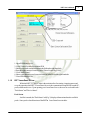
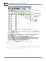
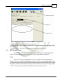
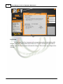
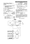
RIFT Operator's Manual &
Technical Guide
© 2010 Zone Systems, Inc.
Zone Managers' Guide to Equipment
Maintenance
© 2010 Zone Systems, Inc.
All rights reserved. No parts of this work may be reproduced in any form or by any means - graphic, electronic, or
mechanical, including photocopying, recording, taping, or information storage and retrieval systems - without the
written permission of the publisher.
Products that are referred to in this document may be either trademarks and/or registered trademarks of the
respective owners. The publisher and the author make no claim to these trademarks.
While every precaution has been taken in the preparation of this document, the publisher and the author assume no
responsibility for errors or omissions, or for damages resulting from the use of information contained in this
document or from the use of programs and source code that may accompany it. In no event shall the publisher and
the author be liable for any loss of profit or any other commercial damage caused or alleged to have been caused
directly or indirectly by this document.
Printed: March 2010 in Dover, DE; USA
Publisher
Zone Systems, Inc.
Managing Editor
Daniel Shurina
Technical Editors
Simon Willetts
John MacBlain
Bhupesh Patel
Contents
3
Table of Contents
Foreword
Part I RIFT User's Manual
1 RIFT Software
...................................................................................................................................
& Control Hardware
0
5
5
Licensing the RIFT
..........................................................................................................................................................
System
6
RIFT LaserGame
..........................................................................................................................................................
Server
7
RIFT Control Centre
.......................................................................................................................................................... 9
RIFT Audio .......................................................................................................................................................... 11
2 RIFT ...................................................................................................................................
Player Hardware
12
RIFT vest
.......................................................................................................................................................... 13
RIFT phaser .......................................................................................................................................................... 15
RIFT outpost .......................................................................................................................................................... 17
Part II Introduction to Equipment Maintenance
19
1 Assigning
...................................................................................................................................
the Right People
19
2 Maintaining
...................................................................................................................................
a Productive Work Area
20
3 Maintaining
...................................................................................................................................
Inventory and Scheduling
20
Part III Maximizing Equipment Up-Time
23
1 Weekly
...................................................................................................................................
Testing
23
2 Quick...................................................................................................................................
Fixes
24
3 Reactive
...................................................................................................................................
Maintenance & Troubleshooting
24
No LED
.......................................................................................................................................................... 25
No Charge
.......................................................................................................................................................... 26
No Sound
.......................................................................................................................................................... 27
No Boot
.......................................................................................................................................................... 27
No Trigger .......................................................................................................................................................... 28
No Laser / No ..........................................................................................................................................................
IR Transmit
28
No IR Receive .......................................................................................................................................................... 28
Index
0
© 2010 Zone Systems, Inc.
3
Part
I
RIFT User's Manual
1
5
RIFT User's Manual
Congratulations on your ownership of the Generation RIFT™ System by P&C Micros™.
This equipment is designed to be a stable, easy-to-use platform in which simplicity and reliability are
the most desirable traits.
For all inquiries pertaining to your equipment, please refer to the following contact
information:
If you are located in North America or South America, your system is supported by Zone Systems,
Inc., based out of Dover, DE.
Zone Systems, Inc.
1055 Barl Court
Dover, DE 19901; USA
Tel. (302) 730-8888
Fax. (302) 336-9698
Web. www.zonelasertag.com
If you are located in Europe, your system is supported by Zone EU Ltd., based out of Leicester,
UK.
Zone EU Ltd.
171 Belgrave Gate, Leicester, LE1 3HS, UK
Tel. +44 116 2425225
Fax. +44 116 2425925
Web. www.zoneeu.co.uk
If you are located in Australia, your system is supported by P&C Micros, based out of Melbourne.
P&C Micros Pty Ltd
5 Harker St, Burwood, 3125, Australia
Tel. +61 (03) 98889333
Fax. +61 (03) 98889001
1.1
RIFT Software & Control Hardware
What is What and Where
Control hardware is comprised of a PC, Monitor, Network Hub/Switch, Printer and ZEB
(Zone Ethernet Base, this is usually mounted biased towards the Arena).
Turning on the PC etc and what should you click to open Laser Game system
© 2010 Zone Systems, Inc.
6
Zone Managers' Guide to Equipment Maintenance
When you first turn on the PC, the RIFT system applications will start automatically.
You will see that it will start executing all the required files on the taskbar:1) Start_VCP.bat
2) RiftRAP.exe
3) ZIOS.exe
4) ZIOS_OSD.exe
5) HSClient.exe
6) InfusionSS.exe
7) RiftGameSvr.exe
8) PrintServer.exe
9) RiftConnect.exe
10) ControlCentre.exe
1.1.1
Licensing the RIFT System
The ZEB (Zone Ethernet Base; Fig. 1), aside from the game computer, is the main piece of
control hardware for your RIFT™ system. It acts as your radio base station, controls licensing
information, and is the connection to arena devices such as outposts, reloads, etc.
Fig. 1
The ZEB is controlled by an additional program called the ZEB Manager.exe (Fig. 2). To
upload a license, follow these steps:
© 2010 Zone Systems, Inc.
RIFT User's Manual
7
Fig. 2
1. Open ZEB Manager.exe
2. Click "Connect" to interface with the ZEB
3. Observe current license information in the field on the right-hand side
4. Enter the alpha-numeric license key in the "Enter License Key" field
5. Click "Send License"
6. Observe the change in your license information in the filed on the right-hand side
7. Close ZEB Manager.exe
1.1.2
RIFT LaserGame Server
While the RIFT™ Control Centre is the main interface for starting / stopping games and
everyday operation, the RIFT™ LaserGame Server is the communication engine between the PC,
packs, and arena devices. Upon opening your LaserGame Server, there are two selectable tabs "Pack Status" and "Device Status".
Pack Status
Just like it sounds, the "Pack Status" tab (Fig. 3) displays information about the available
packs. Some pack-related functions of the RIFT LaserGame Server include:
© 2010 Zone Systems, Inc.
8
Zone Managers' Guide to Equipment Maintenance
Fig. 3
1. Close Game Server - Closes RIFT LaserGame Server.exe (RIFT system will not work
without the game server)
2. Upload Settings to Packs - Uploads the settings.ini file to selected packs (Restores default
programming to the packs)
3. Reboot Selected Pack - Power-cycles the pack selected (on / off)
4. Refresh All Packs - Resets all timeouts to zero and attemps to re-establish communications
5. Clear Games - Clears games from the database (will delete all stored game information)
6. Abort Game - Aborts the packs, but does not retrieve scores
7. Finish Game - Finishes the packs and retrieves scores
8. Start Game - Starts all "Allocated" packs into the selected game format
Device Status
The second tab, "device status," (Fig. 4) displays information about devices like bases,
reloads & mines. All remote devices work from the game computer's AVIL network. Some
device-related functions / displays include:
© 2010 Zone Systems, Inc.
RIFT User's Manual
9
Fig. 4
1. AVIL network scan - Scans for all devices on network
2. Health Bar - Shows the percentage of installed devices that are currently communicating (should
be at 100%)
3. Installed Devices - Shows the device type and status of each installed device
1.1.3
RIFT Control Centre
The RIFT™ Control Centre is the main interface for running games and managing game
formats. There are three selectable tabs at the top: "setup", "pack status" and "details".
Setup
The below screen (Fig. 5) highlights the "setup" tab, which is used for managing game
formats. This screen is used to customize game settings. Switch between game formats by doubleclicking on the desired game selection on the left, then set the game time in the middle field, and run /
abort games with the command links on the right. Double-click on each parameter setting to adjust
it. The "x" next to a game format denotes that particular game format is selected.
© 2010 Zone Systems, Inc.
10
Zone Managers' Guide to Equipment Maintenance
Fig. 5
Pack Status
The "pack status" tab (Fig. 6) manages radio communication with each individual pack ID.
Note the pack status symbols at the bottom of the screen. Double-click the pack alias to block /
unblock a pack. The aliases are static and cannot be changed. There are three pre-configured sets
of names.
© 2010 Zone Systems, Inc.
RIFT User's Manual
11
Fig. 6
Details
The "details" tab allows you to edit your personal information like site name, address, etc.
1.1.4
RIFT Audio
RIFT Audio applications allow the option to configure a single playlist to play through the
game PC and start / stop when the game starts / ends. To configure a playlist, open the RIFT
playlist editor from start -> programs -> P&C micros -> RIFT Audio. A screen similar to the one
below will appear (Fig. 7):
© 2010 Zone Systems, Inc.
12
Zone Managers' Guide to Equipment Maintenance
Fig. 7
To load music files in to the editor, a single playlist must first be created. To create a single
playlist, click the "add" button at the left, name the playlist "default." The playlist must be named
"default" in lower-case letters. Once the playlist has been created, a list of available sound files will
populate in the field to the right. The files that already appear in this field are all arena sounds. Do
not add these arena sounds to the playlist. Instead, click "add" at the right to add .mp3 files into the
"available files" list. They will appear at the end of the list once they are added. Once all desired
sound files are made available, click "modify" in the middle to modify the single playlist. Now you
can double-click on the song titles in the "available files" field to add them to the "default" playlist.
Once your "default" playlist is complete, exit out of the playlist editor, double-click on the RIFT
Audio Synchronizer at start -> programs -> P&C micros -> RIFT Audio to synchronize playlist.
Finally, open the RIFT RAP application in the same folder and leave RAP open and minimized to
enable game control of the playlist.
1.2
RIFT Player Hardware
Definitions
Let the "pack" be defined as the combination of the vest and the phaser (gun), while "vest" is
defined as the vest excluding the phaser and phaser cable. "PCB" stands for Printed Circuit Board.
Background
The RIFT™ vest is designed to be sleek and low-profile to minimize wear and tear on the
electrical components. While the laser is the visual sign of a pack firing, the infrared signal, or IR,
that emits from the gun is the actual means of deactivating the opposing pack. With the RIFT™
system, the vest is only a platform for infrared sensors, LEDs, and the battery charging circuit. All
unique and game-dependent programming is located on the phaser. That means that if you have a
pack called Red 02, and you take the phaser from that pack and move it to another vest, the ID
© 2010 Zone Systems, Inc.
RIFT User's Manual
13
Red 02 follows the phaser to the new vest.
Operation
There are 5 modes through which each pack will cycle during it's lifespan:
1. IDLE - Indicated by a slowly flashing LED pattern; the vest is switched on, but not executing any
commands.
2. START - The LEDs will go dark as the countdown begins to start the game.
3. GAME MODE - Indicated by a rapid flashing LED pattern; The pack is now updating scoring
information to the game PC.
4. END - The "End Game" sound occurs as the pack returns to IDLE mode.
5. CHARGE - The pack flashes solid white LEDs when in charge mode (Note - the pack must be
switched "on" to properly charge the battery).
1.2.1
RIFT vest
The vest, (Fig. 7) shown below turned off. The on / off switch for the vest is located behind
the back PCB facing the player. When the switch is in the "down" position, the pack is turned "on".
Each PCB is equipped with unique infrared sensors, with 2 LEDs on each shoulder, 4 LEDs on
each chest, and 6 LEDs on the back.
© 2010 Zone Systems, Inc.
14
Zone Managers' Guide to Equipment Maintenance
Fig. 8
In-Pack Charging
The packs should be left to charge overnight. Be sure they are switched "on" and they
properly enter charge mode when they are on charge. Take all packs off charge mode when the
first player arrives. Please keep phasers secured to the packs when they are on the racks, and be
sure all charging cables have been removed before players begin reaching for packs. Shown below,
a vest in charge mode (Fig. 8):
© 2010 Zone Systems, Inc.
RIFT User's Manual
15
Fig. 9
Note - It is possible for a pack to appear as though it is in charge mode, but no current is
actually flowing to the battery. This will occur if the pack is switched 'off', or if the plug is not seated
properly in the charging socket. At the end of each night, once the packs are on charge, open the game
server and observe the battery voltage in the 'BVolt' column (see sect. 1.1.2). If the packs are on
charge, the BVolt should read > 4.0. If the BVolt reads any lower than this, the pack is not charging
properly. Try re-seating the charging cable, then note the pack for observation the next morning, at
which point -- power cycle the vest and listen for a stutter upon boot -- signifying improper charging (see
part of sect. 3.3 titled "no charge").
1.2.2
RIFT phaser
The RIFT™ phaser contains all communication and game function circuitry. If the phaser is
not properly connected to a vest, the pack will not know what to do. The figure below (Fig. 8)
shows an open phaser shell with all internal components. The left 1/2 shell (not shown) is equipped
with a speaker and a button-reader attached to a single header. To remove the left 1/2 shell,
remove the "gundom" covering the tip of the barrel, unscrew all 7 x 3mm hex screws and remove the
header from the PCB. All other components stay attached to the right 1/2 shell.
© 2010 Zone Systems, Inc.
16
Zone Managers' Guide to Equipment Maintenance
Fig. 10
Game Functions
Each RIFT
phaser is equipped with two inputs and four outputs.
The inputs include:
1. Hand Sensor - Reads the presence of a second hand underneath the "barrel" of the gun, for safety
purposes. The trigger will not work unless this sensor reads a hand present.
2. Trigger Assembly - Reads the activation of the phaser firing. This activates the laser, IR transmit,
and a firing sound from the speakers.
The outputs include:
1. Laser - Indicates the direction of the fired shot
2. IR transmitter - Projects infrared signal that deactivates opposing packs
3. Speakers - Emit game sounds
4. LCD display - Relays information about game actions (scoring, start / end game, etc.)
© 2010 Zone Systems, Inc.
RIFT User's Manual
1.2.3
17
RIFT outpost
The RIFT™ "outpost" is also called the "base" (Fig. 9). The base will flash the LED color
of the team to which it is assigned. Upon starting and finishing a game, the bases will sound an
alarm, and they will go through different modes of play as they are tagged.
FIg. 11
Each base has 4 settings that are adjusted from the "setup" tab of the RIFT™ Control
Centre (see section 1.1.3). The available base settings are:
1. Off - You have chosen to turn off the Outposts/Bases.
2. Normal - You can only destroy it.
3. Defense - You can destroy it and it will give you a warning and then will tag you or anyone within
the vicinity of the Outpost/Base area
4. Aggressive - You can destroy it but it will not give you any warning and will destroy you or
anyone within the vicinity of the Outpost/Base area
© 2010 Zone Systems, Inc.
Part
II
Introduction to Equipment Maintenance
2
19
Introduction to Equipment Maintenance
It is encouraged that you spend some time familiarizing yourself with the system and your
equipment. With all manufactured items, there is a "bath-tub curve" for faults. This means that most
faults show themselves either in the first 5% or the last 5% of the product's lifespan. All our
equipment is built uniformly and tested thoroughly before it goes out the door, but there is no test as
thorough as real life. If there are any initial conflicts with your equipment, we all want to know about
them before the grand-opening if possible.
Each store is different and has different demands that must be met by the equipment and the
staff, so it is up to you to lay out the foundation of what will become your maintenance culture. This
includes assigning people to particular jobs, holding them accountable with periodic checklists, and
providing them with maintained inventory of spare parts so they can do their jobs well.
2.1
Assigning the Right People
Everyone should be involved in the maintenance culture, but an important decision is to
assign someone as the primary laser tag game technician. This should not be a 16 year-old person
who is in school until 4pm, but someone who is available during the daytime -- someone with whom
our technical support staff can develop a relationship to guide him/her through the more technicallyintensive aspects of his/her job. In many stores, the primary game technician is also a shift manager
or it may be the general manager.
Another important decision is to assign 1-2 shift employees as the equipment testers. There
is no rule that the tester(s) and technician(s) cannot be one in the same. Only the roles are divided.
Testers need only basic computer skills, but you should assign people who are going to be thorough
enough to pick up details like missing screws or buckles on the packs.
Finally, all staff members who are involved with running games should be versatile enough to
solve simple issues on-the-fly. For example, if you've got one pack with a bad gun and another
pack with a bad vest, everyone should think to combine the good gun with the good vest to make
one working pack out of two non-working packs.
To sum up, the following people are going to be involved:
1. Primary Game Technician
i. In charge of troubleshooting equipment glitches & making small repairs, & sending /
receiving repair orders to / from Zone Systems, Inc.
ii. Should be someone available during the day time
iii. Can expect to spend ~ 1-2 hours per week making repairs
2. Equipment Tester(s)
i. In charge of testing equipment, uploading settings / sounds to packs, & completing weekly
checklists to be handed over to management and the primary game technician
ii. Should be someone available when the store is closed for 1-2 hours per week to test
equipment
© 2010 Zone Systems, Inc.
20
Zone Managers' Guide to Equipment Maintenance
3. Game Shift Employees
i. In charge of labeling faulty equipment when it is brought to their attention, and may be
responsible for making quick 1-2 minute repairs.
ii. Should be enthusiastic about their job, well-trained on your company procedures for
handling maintenance, and versatile enough to think outside the box at times.
2.2
Maintaining a Productive Work Area
In order to properly maintain your equipment, a clean area is necessary in which tools and
parts are easily accessible. A clean, well-lit, flat-top bench should be made available that is large
enough to lay one vest flat from end-to-end. Adequate power outlets should be available as well as
a maintained tool kit. The recommended tool kit should include:
·
·
·
·
·
·
·
·
·
·
1 x 2.5mm hex screwdriver
1 x 3.0mm hex screwdriver
1 x pair needle-nose pliers
1 x pair side-cutters (snips)
1 x jewelers flat-head screwdriver
1 x jewelers philips-head screwdriver
1 x hot glue gun
1 x roll electrical tape
1 x multimeter -- with continuity, DC voltage, & DC current measurements
1 x soldering pen -- for soldering / desoldering wires only (not for use on circuit boards)
An additional option is to have an area near the work bench to hang 2-3 tagged vests and
available charging cables are an added benefit in order to test packs for charging or to keep packs
charged that are not being used.
2.3
Maintaining Inventory and Scheduling
Inventory:
To keep a well-maintained site, it is recommended that you keep a stocked inventory of
commonly-used consumable parts as well as a few replacement circuit boards for repairs. This will
help minimize your downtime and save shipping cost by handling common issues in-house rather than
sending easily-fixed problems to Zone Systems for repair. A list of replaceable parts to keep on
hand includes:
· 1 x box 4x25x3mm hex screws (gun)
· 1 x box 4x20x3mm hex screws (gun)
· 1 x box 4x16x3mm hex screws (gun)
© 2010 Zone Systems, Inc.
Introduction to Equipment Maintenance
·
·
·
·
·
·
·
·
21
1 x box 4x12x3mm hex screws (vest)
4 x 1/2 phaser shell (2L, 2R; with speaker, trigger, etc.)
3 x curly phaser cables
3 x D-rings with gun straps (gun)
4 x gundoms (gun)
1 x roll lead-free solder
5 x hot glue sticks
4 x replacement speakers
Please email [email protected] for pricing information.
It is not as common that faults occur with the circuit boards as with parts like cables and
speakers -- but in case it does happen, a list of recommended spare circuit boards to keep on site
includes:
·
·
·
·
·
·
·
1 x RIFT™ left shoulder board
1 x RIFT™ right shoulder board
1 x RIFT™ left chest board
1 x RIFT™ right chest board
1 x RIFT™ back board
2 x RIFT™ LCD display
2 x RIFT™ laser / IR module w/ hand sensor
Scheduling:
The goal of effective scheduling is to be at 100% availability every Friday night. This means
that all your packs are functional by the start of your busiest days of the week. The key to
successful operation during your up-time lies with how successfully you handle your down-time. In
other words, take advantage of closed hours to maintain your equipment.
Scheduled maintenance is a two-fold attack. The first part consists of the equipment tester
(s) testing the equipment and completing the Zone Systems recommended checklist, available in the
appendix.
The second part of scheduled maintenance includes the primary game technician performing
repairs on any packs that have been taken out of service, then addressing issues brought to his/her
attention by the secondary game tech(s). This should be done during closed day-time hours.
© 2010 Zone Systems, Inc.
Part
III
Maximizing Equipment Up-Time
3
23
Maximizing Equipment Up-Time
Anyone who can use a screwdriver has an opportunity to save your store downtime. A
couple common faults that display themselves in games are that the gun stops working properly or
the vest completely dies. The game operators are busy, so they are not expected to perform actual
repairs that take longer than 2 mins -- however the faster and more accurate they can label a pack
with a particular issue saves the operator time he/she could be spending running games; and it saves
the game tech time isolating pack issues.
With the RIFT™ system, a low battery (<3.75VDC) will cause intermittent failures
with LEDs, lasers, IR sensors & emitters, and radio communications. If any of these
faults are observed, check battery voltage first, then try swapping the battery with one that
is fully-charged.
Preventative maintenance, for our purposes, consists only of testing and noting known faults.
This allows smaller problems to be addressed before they become big problems. Contradictory to
popular thought, spending a couple hours per week testing equipment actually decreases the amount
of time required for service. Over the years, we have seen many sites who do not address issues
until they put a pack completely out of service. The packs continue to pile up until the game tech has
an opportunity to work on them (usually once / week), but he/she is only addressing major issues
and seems to be unaware that while the packs that are out of service are going back in service, the
following week's issues have already begun manifesting in the packs that are, at this point, still
operational. Therefore, he/she never gets "ahead of the game."
3.1
Weekly Testing
Weekly Testing & Checklists
Please see Appendix for a basic testing checklist to be completed the following testing
procedure. Record the date, name(s) of tester(s), as well as any additional issues for the technician.
Testing Procedure
Have your tester(s) perform the following testing procedure once / week, beginning the
testing procedure while the packs are still on charge after a full night of charging, preferably at the
beginning of the week so the primary game technician has an opportunity to address the issues
before the following Friday.
1. Visually look around the vesting room and take note of the LED colors while the packs are in
charge mode. If a pack is in charge mode, but has some LEDs emitting the wrong color, note the
pack as "no LED."
2. Grab one vest and plug / unplug the charging socket. Make sure it goes in/out of charge mode
properly. If it does not, please determine if the appropriate voltage (~4.5 - 4.9 VDC; center-
© 2010 Zone Systems, Inc.
24
Zone Managers' Guide to Equipment Maintenance
positive) is received at the charging cable. If it is, mark the pack as "no charge." If proper voltage is
not supplied by the charging cable, mark the charging cable for the technician to address but do not
use it in the meantime. Leave all charging cables unplugged before continuing to the next step.
3. Visually inspect each vest for missing or broken buckles and for missing screws. If a buckle is
broken or missing, note the pack ID on the checklist as "no gun buckle" or "no vest buckle"
depending on the location of the bad buckle. If a screw is missing, note the pack ID on the checklist
as "no screw."
4. Power cycle each vest (off & on) and listen for the boot-up sound. If no boot sound is audible,
note the pack as "no sound." If the pack stutters badly upon boot-up, or does not boot up
correctly, note the pack as "no boot."
5. With all packs switched on, in "idle" mode -- start a solo game from the game server. Try
shooting each pack. If a pack's trigger does not engage properly, note the pack on the checklist as
"no trigger." If a pack shoots but does not fire laser, note the pack on the checklist as "no laser."
Now try tagging other vests with the pack being tested. If it does not tag other packs, note the pack
on the checklist as "no IR transmit." Check to make sure that all packs make the firing sound. If a
pack does not receive tags from other packs, note the pack on the checklist as "no IR receive." If a
pack does not make the firing sound, note the pack on the checklist as "no sound."
3.2
Quick Fixes
Quick Fixes During Games
Some of the more common issues that happen during games and some quick fixes to try
include:
Pack completely dies Try changing battery with fully charged; wash out power switch with tech
spray
Stutter sound during Can be caused by a flat battery - Try changing battery with fully charged; then
boot-up
mark for the technician
Unusual LED pattern Can be caused by a flat battery - Try changing battery; then try uploading
settings from the game server after game has ended (See Section 1.1.2).
No laser
Can be caused by a flat battery - Try changing battery with fully charged; then
mark for the technician
No IR emit or receive Can be caused by a flat battery - Try changing battery, then mark pack for the
technician
3.3
Reactive Maintenance & Troubleshooting
When it comes to troubleshooting pack faults, the answer is basically always the same: No
matter what the fault, the first step is to get a 100% working pack for comparison to the
© 2010 Zone Systems, Inc.
Maximizing Equipment Up-Time
25
malfunctioning pack. Once the two packs are staged (good pack vs. bad pack), begin moving
components, one-by-one, from the bad pack on to the good pack, until the fault is isolated to a
single component. Once the fault is isolated, either replace the faulty component or send it to Zone
Systems for repair.
3.3.1
No LED
1. No LED Identified by: one or more colors not functioning properly on the pack, but the pack still
boots and displays site ID information on the LCD display
Testing: Open the back cover, and move the selector switch to "4" (See Fig. 10; below).
The vest will start cycling through the 3 LED colors. Determine which color is malfunctioning. Only
1 x bad LED will cause 1/2 the LEDs to malfunction.
© 2010 Zone Systems, Inc.
26
Zone Managers' Guide to Equipment Maintenance
Fig. 12
Fixing: Determine the PCB that is at fault by unplugging vest cables one at a time until you
can narrow the problem down to one particular PCB that is knocking out the LEDs on the other
PCBs. Note - if unplugging both cables from the back PCB does not fix the problem, the problem
is with the back PCB. After you've determined the faulty PCB, swap with spare and send the bad
PCB to Zone Systems, Inc. for repair.
3.3.2
No Charge
2. No Charge Identified by: (1) The pack may not go into charge mode when plugged in to a charging unit,
or (2) the pack may go into charge mode, but still behaves as though the battery is flat once
removed from charge.
Testing: Measure voltage at the charging cable. It should read ~4.5-4.9VDC, centerpositive. However, (2) It is possible for the vest to go in charge mode, but no charge is actually
reaching the battery. To determine if charging is functional, use a modified charging cable with an
open + line to use with an ammeter (see Fig. 11, below). Note - a modified cable for current
measurement is available for sale from Zone Systems, Inc.
© 2010 Zone Systems, Inc.
Maximizing Equipment Up-Time
27
Fig. 13
Fixing: Whether the pack does not go into charge mode (1), or if the pack does go into
charge mode but does not take current (2); troubleshooting steps are the same. The problem is
probably with the back PCB, but to make sure, open the back cover, disconnect the vest cables
and disconnect the gun cable. Then, plug into the modified charging cable. If it charges properly,
the problem is either with the gun or another PCB on the vest -- and the problem can be traced to
an individual PCB. On the other hand, if it does not charge properly, send the back PCB to Zone
Systems for repair.
3.3.3
No Sound
3. No Sound Identified by: The pack does not make proper sounds.
Testing: The pack will not make the proper sounds if the battery voltage falls below
3.75VDC. First, open the back cover, disconnect battery and check battery voltage.
Fixing: If the battery voltage is below 3.75VDC, try swapping with a fully-charged battery.
If the battery was on charge all night and still has a flat battery, see troubleshooting item #2, "No
Charge." If there is a "stutter," it is most likely a low battery problem. However, if sounds are
missing, send the RIFT™ phaser to Zone Systems for repair.
3.3.4
No Boot
4. No boot Identified by: The pack does not make the proper sound on boot-up, and does not display
the site information on the LCD display.
Testing: Flat batteries will cause the pack not to boot properly. Open the back cover and
disconnect battery to test battery voltage. If < 3.75VDC, the battery is probably just too low, so try
© 2010 Zone Systems, Inc.
28
Zone Managers' Guide to Equipment Maintenance
changing with a new battery. If the battery is flat after being on charge all night, see troubleshooting
item # 2, "No Charge". If the battery voltage is above 3.75VDC, continue to fixing.
Fixing: If the pack does nothing, try blowing out the power switch with some "Tech Spray,"
available for sale from Zone Systems. Note - compressed air works, too, but not nearly as well.
Sometimes they get clogged with dust. If this does not fix the problem, try swapping components
from faulty vest on to a working vest until you narrow the fault to a single PCB, then send that PCB
to Zone Systems for repair (fault will probably be with the back PCB or the phaser PCB).
However, if the pack does the wrong thing (something glitchy), try uploading settings from the game
server. If this does not fix the problem, swap components until you narrow the problem to a single
PCB, and send that PCB to Zone Systems for repair.
3.3.5
No Trigger
5. No Trigger Identified by: The pack does not make the firing sound when the trigger is pulled, and no
clicking sensation is felt.
Testing: Open the phaser shell and see if the metal tab and spring are still in tact.
Fixing: If the metal tab is in tact on the microswitch, try adjusting the bend so it engages the
switch better. If the microswitch has come apart, replace the microswitch with a spare.
3.3.6
No Laser / No IR Transmit
6. No Laser / No IR Transmit Identified by: The pack does not have visible laser (no laser) or the pack does not deactivate
opposing packs in game mode (no IR transmit).
Testing: Open the RIFT™ phaser and inspect the wiring that goes between the 12-pin
header at the front of the phaser PCB and the laser / IR module (see section 1.2.2).
Fixing: If the wiring is worn or broken, simply repair with solder and hot glue. If the wiring
looks good, try swapping the laser / IR module with spare. If this does not fix the problem, send the
phaser to Zone Systems for repair.
3.3.7
No IR Receive
7. No IR Receive Identified by: The pack does not deactivate when shot by an opposing player during a solo
game.
Testing: Open the back PCB and turn the selector switch to "2". Disconnect phaser and,
using a Nexus Hand-Held Remote (available for sale from Zone Systems), press "*" until "mode
© 2010 Zone Systems, Inc.
Maximizing Equipment Up-Time
29
4" is selected. Then enter "555" to enter the hidden "mode 5". Now, aim the remote at each PCB
on the vest and press "7". The LED on the back PCB should light up red each time a PCB is
tagged.
Fixing: If no PCBs are tagged, send the vest to Zone Systems for repair. If only some PCBs
are not tagged, replace those PCBs with spares and send faulty PCBs to Zone Systems for repair.
© 2010 Zone Systems, Inc.