1
SIMIAN PLUS: A MISSION SIMULATION ENHANCEMENT TOOLKIT
A Paper
Submitted to the Graduate Faculty
of the
North Dakota State University
of Agriculture and Applied Science
By
Divya Govardhana Dayala
In Partial Fulfillment
for the Degree of
MASTER OF SCIENCE
Major Department:
Computer Science
August 2013
Fargo, North Dakota
North Dakota State University
Graduate School
Title
SIMIAN PLUS – A MISSION SIMULATION ENHANCEMENT TOOLKIT
By
Divya Dayala
The Supervisory Committee certifies that this disquisition complies with
North Dakota State University’s regulations and meets the accepted standards
for the degree of
MASTER OF SCIENCE
SUPERVISORY COMMITTEE:
Kendall E. Nygard
Chair
Gursimran Walia
Samee Khan
Approved:
1-27-2014
Date
Brian M. Slator
Department Chair
ABSTRACT
Unmanned Air Vehicles (UAVs) have the ability to execute missions that include
detecting and destroying the targets. The Simian simulator developed at NDSU performs
complex motion calculations for
moment - moment flight and delivers effective inter-agent
communication for all the UAV’s. Scenarios that focus on the strategy plan and perform
calculations have been, developed to carry out the mission. The goal of this paper is to address
the tasks of starting servers, manually writing the required xml files to describe scenario to the
simulator and launch simulation in the existing Simian system. Simian Plus is, designed and
implemented to ease the process of building and launching simulation. It is, aligned to the key
principle “Open- agent architecture” of Simian.
iii
ACKNOWLEDGEMENTS
I take this opportunity to express my gratitude to Dr. Kendall Nygard for his
immense support. Appreciate his time and help for setting me in the right direction to
achieve my goals. My sincere thanks to, Dr. Gursimran Walia and Dr. Samee Khan for
serving on the committee. I would also like to thank my fellow researchers, whose work
has helped me gain knowledge and build the enhanced system.
iv
TABLE OF CONTENTS
ABSTRACT ................................................................................................................................... iii
ACKNOWLEDGEMENTS ........................................................................................................... iv
LIST OF FIGURES ...................................................................................................................... vii
1.
INTRODUCTION ................................................................................................................... 1
1.1. Objectives ............................................................................................................................. 3
2.
BACKGROUND ON EXISTING ARCHITECTURE ........................................................... 4
2.1. Simulator Layout .................................................................................................................. 4
2.2. Launching Simulation .......................................................................................................... 6
3.
MOTIVATION AND PROBLEM DESCRIPTION ............................................................. 10
4.
PRINCIPLES OF DESIGN ................................................................................................... 13
4.1. Development Platform ....................................................................................................... 13
4.2. Visibility/Interface ............................................................................................................. 14
4.3. Affordance .......................................................................................................................... 15
5.
LAYOUT - SIMULATION GRAPHICAL INTERFACE .................................................... 17
5.1. Mechanism to Create New Scenario .................................................................................. 17
5.2. Mechanism to Launch New Scenario................................................................................. 22
5.3. Mechanism to Launch Saved Scenario .............................................................................. 22
5.4. Implementation................................................................................................................... 23
5.5. Validation ........................................................................................................................... 34
v
5.6. Output – Scenario ............................................................................................................... 35
6.
CONCLUSION ..................................................................................................................... 43
7.
FUTURE WORK .................................................................................................................. 44
7.1. Search Strategy................................................................................................................... 44
7.2. Enhance Validation ............................................................................................................ 44
8.
REFERENCES ...................................................................................................................... 45
APPENDIX A. LAUNCH SIMULATION SERVLET PROGRAM ........................................... 46
APPENDIX B. LAUNCH_VIS2D SERVER PROGRAM .......................................................... 52
APPENDIX C. LAUNCH_DXML PROCESSOR PROGRAM .................................................. 66
vi
LIST OF FIGURES
Figure
Page
2.1. Layers of Simian Simulator ............................................................................................... 5
2.2. Arguments Tab View ......................................................................................................... 7
2.3. Console View after Opening the Port ................................................................................ 8
2.4. ‘Run Configuration’ to Start the Client ............................................................................. 8
2.5. Passing the Location of Scenario-Description Files .......................................................... 9
5.1. Create Base Model ........................................................................................................... 17
5.2. Configure the Flying Agent’s Base Model Hardware ..................................................... 18
5.3. Enter Number of UAVs ................................................................................................... 19
5.4. Configure and Add Flying agents .................................................................................... 20
5.5. Add Boundaries ............................................................................................................... 21
5.6. Add Target Position ......................................................................................................... 21
5.7. Simulator Specifications .................................................................................................. 22
5.8. Target Locations .............................................................................................................. 25
5.9. Base Model and Hardware for UAVs .............................................................................. 26
5.10. Team of Flying Agents and Targets............................................................................... 29
5.11. Dimensions of the Field ................................................................................................. 31
5.12. Pass Port to Client (Loislane) & Simulation Details ..................................................... 33
5.13. Invalid Fields Highlighted ............................................................................................. 35
5.14. Output – After Configuring the (UAV) Model .............................................................. 37
5.15. Output – Team of UAVs ................................................................................................ 38
5.16. Output – After Assigning the UAVs Position and Configuring Controllers ................. 38
vii
5.17. Output – After Creating a Team of Targets ................................................................... 39
5.18. Output – After Assigning Each Target’s Position ......................................................... 39
5.19. Output – After Configuring the Field’s Dimensions ..................................................... 39
5.20. Output – After Configuring the Simulator ..................................................................... 40
5.21. Output – After Running the ‘Visualizer’ ....................................................................... 40
5.22. Output – After Successfully Opening the Port .............................................................. 41
5.23. Output – After Creating the Configuration File ............................................................. 41
5.24. Output – After Launching the Simulation ..................................................................... 42
5.25. Output – After Destroying both the Targets .................................................................. 42
viii
1. INTRODUCTION
Advancements in technology have replaced the need for manned aircrafts in search/destroy,
reconnaissance and surveillance missions. Unmanned Air Vehicles (UAVs) have the ability to
execute missions that include detecting and destroying the targets. This unique feature of
technology has gained a lot of attention due to the risk factor and complexities involved in
today’s world of warfare. UAV are equipped with hardware like sensors, receivers and weapons
that enable it to search a pre-defined zone and respond as commanded. Based on the strategy of
the mission, they destroy the detected target. A mission involves either a single UAV or a team
of UAV that are, focused towards eliminating the need of human intervention. Configuring, each
UAV with the hardware, planning strategy, helps in efficiently and effectively carrying out the
mission in complex challenging battlefield scenarios.
NDSU has developed a Simian simulator that calculates the step-by-step flight motion of
each UAV [1]. It also provides the complex calculations for effective inter-agent communication
among the team of UAVs. The simulator comprises of a ‘Visualizer’ (Launch_ Vis2d) and
Lioslane that plays the role of a client. The server and the client communicate with each other
using the sockets. The Lioslane (client) sends the stream of calculated information to the server
that gives a visual of the ongoing mission. The Environment class is the core element that
performs the repeated calculations for laying out the flight path positions of each UAV involved
in the mission. This helps in easing the process of performing the complex calculations for
determining the UAV motion control and the inter agent communication in the area of interest
and enables us to build on top of the Simian simulator for demonstrating various battle scenarios.
Each of the battle scenario situations can be simulated with specific number of targets and the
1
UAVs. The hardware for the UAVs includes sensors, receivers, transmitters and weapons that
enable the single based communication among the team of UAV. This paper focuses on paving a
way to easily add UAVs and targets to a battle scenario assemble hardware for each UAV, assign
controllers, specify the area of interest and the place the targets in the field.
The existing simian simulator has a good implementation of the strategy to execute a
mission. However, the initial phases of the simulation like the scenario description, starting the
server until invoking the client to start the calculation of the flight path is a tedious job. Attention
needs to be given, to the detailed problem description such as specifying the whereabouts of the
targets, configuration of hardware which play a key role in inter-agent communication,
specification of each air vehicle along with controllers that aid in not just laying out the strategy
plan but also in executing the mission, simulation specifications that describe the port number
the client should be using to interact with the server to visualize the mission, time-step that
indicates the time gap, between each command that is passed for the server , simulation time
indicates the span of time the simulation should be carried on. With the given description of
some of the elements that are key to creating a scenario and launching it, equal prominence
needs to be given to the format and metrics of the input files. Thus, importance needs to be given
to the job of creating these input files such that, the simian can interpret and perform the required
calculations to launch and visualize the mission.
The goal of this paper is to address these tedious tasks of starting servers, manually
writing the each of four input files and launch the simulation. Simian Plus, is designed and
implemented to ease of the process of building and launching simulation, strictly aligning to the
2
key principle of “Open- agent architecture” of simian. Below are objectives that Simian Plus
tackles.
1.1. Objectives
Provide a simple method to start the server that visualizes the simulation.
Automate the process of passing the location of the four input files and starting
Loislane (client)
Mechanism to create, describe and configure each of the agents involved in the
mission.
Mechanism to launch the newly created and assembled battle-scenario
Mechanism to the save configuration file and provide an easier method to launch
them.
This paper illustrates the significance of the core elements required for creating a
scenario, discusses the design of the enhanced system and explains how it is been implemented
to achieve the above-mentioned objectives. Chapter 2 and Chapter 3 illustrate the current
procedure for operating simian, start server and pass the manually created four input files.
Chapter 4 begins with the layout of the user-friendly Interface, which replaces the existing
Simian. It shows the systematic procedure to configure the available hardware and the flying
agents. Chapter 5 encloses the significance of each core element that make up the entire battle
scenario’s ‘problem-description’ along with detailed implementation of all these features in
Simian Plus, to achieve each of the previously mentioned objectives.
3
2. BACKGROUND ON EXISTING ARCHITECTURE
This chapter illustrates the architecture of simian and the outline of the components that
carry out mission. The plan and a brief layout of the components to achieve inter-agent
communication among the flying agents is discussed. It then describes how each of these
elements, is specified to simian using the xml files. A systematic procedure for starting the main
server and triggering the processor to perform the calculations in the existing simian system is
described with visual figures.
2.1. Simulator Layout
The simulator developed at NDSU is the combined effort of the research team led by
Dr.Kendall Nygard [1]. It is a means of simulate the battle scenario and visualize the strategy
plan executed by the UAVs for searching and destroying targets.
Simian uses the Open Agent Architecture and written in Java. The major components are
the agents, environment and the mechanisms for communication. Agents are the entities that
have the capability to navigate, change direction and transmit signals. These agents register with
the ‘environment’, which handles all the inter-agent communication [6]. This helps in the quick
message passing among the Unmanned Air Vehicles. Invoking a method of the higher-level
object always does message passing. However, this object does not have a reference to a lower
level object. Sensors, Transmitters and Receivers are the devices that enable communication by
transmitting and receiving the signal objects. Another important element is the ‘Controller’,
which performs the calculations for moment-by-moment flight path.
Simian is a java-standalone application. It uses Java-Sockets for communication between
the client (Lioslane) and the main server (Vis2D). XML files are used to describe the scenario
4
and hold the specifications for the targets, UAV and the Area of interest. “Situation”, “Policy”,
“Strategy” and “Global” are the four xml files that server as input. They hold the hardware
configurations of UAV, Controllers, locations of targets and the area of interest dimensions.
Simian supports the three dimensions making closer to the realistic scenarios in the battlefield.
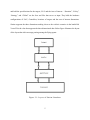
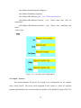
Vector3D is the class that supports the three-dimensional data. Below figure illustrates the layout
of the layers that aid in message passing among the flying agents.
Figure 2.1: Layers of Simian Simulator
5
Environment: The environment layer registers all the details of each agent in the system.
It releases the information of these things/agents as needed for facilitating
communication between UAV’s. Messages are passed to the physical objects/agents and
extracts messages as well. This layer handles issues such as crashing and radio messages
[6].
Physical Layer/Flying Agents: The flying agents represent a physical object, UAV.
Situation file specifies the flying agents and the targets. It contains the hardware devices
for communication and the weapons needed for destroying the identified targets in the
field. Elements required for UAV motion control are included. “msgsUp” and
“msgsDown” are called to pass the data to the ‘environment’ object, as required during
the mission [2].
Autopilot/Strategist: Vehicle is a controller used for specifying the strategy. It can be
termed as ‘Vehicle Control’ or ‘Autopilot’. It is a standard controller used by Simian, to
translate the high-level commands into smaller pieces of details that are interpretable by
the ‘physical objects’. This helps in writing code that aligns to the high-level goals of
Simian [8].
2.2. Launching Simulation
Running Simian needs a Java virtual machine; jar files ‘dom4jh.jar’ & ‘jaxen.jar’ for
compiling and handling the input XML files. Compile the java code in the package
‘Orion/simian [3]. XML files ‘situation’, ‘strategy’, ‘policy’ and ‘global’ are the input for
launching the configured battle scenario. There are two options for launching the scenario.
Eclipse is one of the options that ease the process of, compiling and launching the simulation.
6
Below are the detailed steps involved to setup and instantiate the simian for starting the
simulation process.
Step 1: Set-up Project
Import the project into eclipse. This helps in distinguishing different packages. The
alternate way of compiling/running the application is using the command prompt. “Quick
start guide to the SimianPlus/simulator” can be referred for the sequence of steps
needed.[1]
Step 2: Start Server
To start the server, right click on the Vis2D.java and choose “Run Configurations”.
Create a new java application configuration and select ‘Vis2D’ as the main class. Below
is the screenshot of how the eclipse’s configuration window looks.
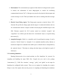
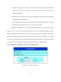
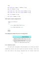
Click on the “Arguments” tab, in the “Program Arguments” to pass the port number, the
server should run on. Below figure is the screenshot that depicts the process for passing
the port number to the server.
Figure 2.2: Arguments Tab View
7
If the port number entered is available, server opens the port. The message displayed on
console, for successfully opening the port can be seen in the below figure.
Figure 2.3: Console View after Opening the Port
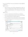
Step 3: Running the client
a) Pass the four-xml files as input to the simian’s xml processor. For this, right click on the
DXML.java and once again choose “Run Configurations”.
b) Next create a new java application configuration and then select ‘DXML’ as the main
class. Below is the visual of the ‘run configuration’ window for instantiating the xml
processor.
Figure 2.4: ‘Run Configuration’ to Start the Client
8
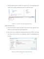
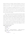
c) Click on Arguments tab, and then add the location of scenario specific, xml input files.
The figure given below shows the arguments tab, where the location of each file is
passed.
Figure 2.5: Passing the Location of Scenario-Description Files
By following the above steps and initiating the simulator, ‘DXml.java’ starts analyzing
and sorts each of the user specified XML files (policy.xml, strategy.xml, situation.xml and
global.xml) into a linked list. It then identifies the available models, teams, list of agents and the
other entire scenario related details. This in-turn starts the socket-client ‘Loislane.java’. It
communicates with the server using the specified port number for passing the information related
to the simulation and the commands to the flying agents. The server listens and uses this
information to visualize the mission.
9
3. MOTIVATION AND PROBLEM DESCRIPTION
The Simian simulator developed at NDSU performs complex motion calculations for
moment - moment flight and delivers effective inter-agent communication for all the UAV’s.
Many scenarios that focus on the strategy plan and perform calculations to carry out the mission
are, implemented. This chapter discusses the framework design and refreshes the repetitive
processes that are involved in starting and running the existing Simian system, until the
visualization of the mission as noted in the previous chapter.
One of the design goals of Simian is to have the scenario/problem description separate
from the strategy that leads to the concept of Open Agent Architecture. Hence, there are four xml
files used for describing the scenario that involves targets, perimeters of the field, Unmanned Air
Vehicles and the hardware configurations for each of those agents [6].
Situation, Policy,
Strategy and Global are the xml input files passed manually as input arguments to DXML class.
Situation file holds the definition of two models, one for flying object and the other for target. It
holds the parameters of speed, forward, backward, turn, up & down acceleration. The flying
object has the elements like receivers, transmitters, weapons and sensors. To specify the no of
UAVs for a configured model, same file is used. Policy file holds the three-dimensional
specifications for the area of interest. Details related to the visualization of the mission such as
time-step, time limit, port number is stored in Global file. Listed below is summary of the
tedious tasks involved in running simian.
Creating the configuration to start the server and run it as java application.
Repetitive process of creating another configuration setting, to launch the client as
java application
10
Handwritten ‘Situation’ file, to describe scenario.
No flexible way for building a new model and configuring each agent involved in the
mission.
Constructing the xml file that holds the required configurations, formatted so that
simian can interpret the data.
Pass the location of each input file, manually.
The goal of this paper is to address the above-mentioned repetitive and tedious jobs involved in,
describing a scenario and assembling the required hardware for each of the unmanned air
vehicles. For this, a user friendly graphical interface ‘Simian Plus’, has been developed that
offers a flexible way for configuring the battle scenarios, ability to configure each of the
hardware piece that make up the flying agents which execute the mission. The main objectives of
this paper are, listed below.
1. Means to create and describe a scenario.
Flexible way to construct a base model for an unmanned air vehicle
Ability to configure each of the hardware assembled in the base model.
2. Means to save and launch the newly created scenario-configuration file.
Void the process of creating ‘run configuration’s to launch Simian as java
application, for both server and client (DXML).
Automate the process of creating and saving the scenario-description file in the
correct format without hindering the existing simian way of interpreting the fourxml files.
3. Means to pass the simulation specifications such as time-step, simulation time limit
etc. with ease.
11
4. Means to launch the previously configured files and trigger the simulation process
with ease.
Easier method to launch the previously created scenarios, without having to
neither recreate the scenarios nor pass the location of the input files.
12
4. PRINCIPLES OF DESIGN
In the past, applications and software was, designed with little regard for the user, so the
user had to figure out a way to adapt to the system for starting/running the program. With this as
the one of the key goals, Simian Plus is, designed to eliminate this approach and instead aid the
user in using the system with ease. User Interface facilitates interactions between a system and
people. In our case, an application and the researcher working towards formulating a
configuration that can simulate the mission strategy. This chapter discusses the user interface
design, concepts that aid in building an effective and functional application.
The interaction designer needs to take into account as to who the target of the GUI/web
application is and who will be using it. Based on this, UI designer needs to place emphasis on
what the goal/purpose is and how it can be, achieved. Key inter actions have to be identified and
wire-framed or create interfaces. There is a possibility for numerous ideas running through, but
the application design should align to certain key items to stop it from been overloaded with
features. Below are some of the design principles that aid in creating a functional, clutter free
User interface.
Development, visibility and affordance are the three factors that are, vital factors that aid
in creating an interface. They help in keeping the interface not just clutter free but also
functional.
4.1. Development Platform
Platform constraints such as the technology used in implementing the UI, backend
technology used to integrate with the front end, ease of developing features and integrating with
the existing framework, libraries and tool kits are the foundations of an application. Action13
script, j-query and JavaScript are some of the technologies that can be used to implement the
user interface.
In Simian Plus, JavaScript is used as the front-end technology, as it has proved to be a
simple yet functionally effective scripting language. Java is used as the backend technology that
performs the required calculations to execute the mission. To bridge the front end and back end,
‘Servlets’ have been used. Java servlets are server-side java program modules that process the
client-server requests. In other words, it acts as an intermediary between the client/front-end and
the back-end. Since a servlet is integrated with the Java language, it also possesses all the Java
features such as high portability, platform independence, security and Java database connectivity
4.2. Visibility/Interface
Clear conceptual model, human abilities, product identity are some of the factors that
express, a strong visual identity and are thus termed as the Visibility factors. A well-designed
interface is one that allows a user to recognize the context of available controls at a glance. This
way/mode of interaction refers to all graphical techniques that are, used to convey the context of
the application. Below are the key elements that help in laying out the initial design/architecture
of an application’s user interface.
Consistency: The same conventions and rules should be, applied to all the elements
of the graphical interface. Font, abbreviations, terms, data formats, units of
measurement are the elements that play a key role in achieving consistency. The user
establishes a connection with the application as they use the graphical interface. For
example using the same set of colors and font for the entry/input objects, different
font/style for the titles helps the user to use the application with ease.
14
Screen Layout: Organization and location of displayed data elements have to be
standardized. This allows the user to develop spatial expectations. The screen has to
be, divided into three basic segments, with each reserved for specific functions. Place
the objects in one section of the UI and the actions such as “Save”, “Cancel” in a
different section of the interface. This helps the user in distinguishing the input/entry
areas from the ‘next action’ area. The topmost segment holds the title that describes
what the screen/page is, about. Usage of real world metaphors is another factor that
helps the user.
Relationship: Related data has to be, grouped or ‘chunked’ together. Placing related
items and eliminating unrelated items helps in achieving visual organization. By
grouping elements, users can gain better understanding of the application.
Navigation: Items in a list, should be arranged in some recognizable and useful
order, such as chronological, alphabetical, or degree of importance. When multiple
data elements appear on a single line, e.g. line number, authority heading(s) and
number of related records-the data elements should be broken into separate blocks or
tabular display and not run together. User interface navigation should always start
with strong entry points. An entry point can be a simple welcome page with a
company/university logo and a button that says, “Click here to Begin” or “Start” .The
options should be what the user would anticipate from the system.
4.3. Affordance
Developing better visual (color or black-and-white) communication is an important part
of making computer graphics that communicate effectively and efficiently through graphic
design. Affordance is the quality of an object that provides a user with the visual cue to perform
15
an action. The user should naturally perceive how to interact with the application objects and
quickly determine:
What can be pressed
What areas need input
What areas provide feedback
Simulation of a scenario includes a single java thread. The existing Simain uses the four
user specified xml files to initialize this thread. Simian-Plus voids the manual process of creating
four files and passing the file locations. On clicking “Run Simulation” button, related java thread
is, initialized.
Eclipse IDE (Integrated Development Environment) is a useful tool that helps in writing
and executing the code. It comprises of basic workspace and extensible plug-in feature making
the customization of an environment easy. The plug-in architecture supports creating
applications using various programming languages such as C, Python etc. including networking
applications such as database management and telnet.
systems such as CVS, Teamprise explorer and GIT.
16
It also supports the version control
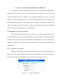
5. LAYOUT - SIMULATION GRAPHICAL INTERFACE
To demonstrate the user-friendly features that have been designed and implemented in
Simian Plus, this chapter illustrates the steps that enable a simpler and easier way for the
‘scenario-description’ process in Simian. As an example, Simian Plus is used to, create and
configure a scenario that comprises of two UAVs to search the targets. The area of interest is a
horizontal field and contains two static targets. One controller is, assembled for each of the air
vehicle. The flying agents use ‘Lawn mow’ strategy to detect and destroy targets. User Manual
can be, referred to for details on how to set up the project.
5.1. Mechanism to Create New Scenario
This section, talks about the steps for creating a new scenario using Simian Plus. In
current Simian, the only way to specify the hardware for a base model of a flying agent was, by
manually creating xml tags, elements and attributes. Each hardware has its own element name,
confining to which the user would have to pay keen attention in creating the first input xml file,
“Situation.xml”.
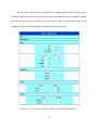
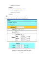
5.1.1. Construct base model
Simian Plus has implemented a feature where the base model is, constructed with ease.
Below figure, shows the available hardware that can be equipped to a physical flying agent. A
unique name and the count of hardware can be, specified to build a basic model.
Figure 5.1: Create Base Model
17
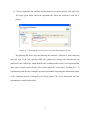
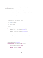
The next figure shows the screen displayed, to configure hardware that a flying agent is
equipped. This feature in Simian Plus not only replaces the monotonous way of manually writing
the xml but also provides a flexible way to the user. It helps in trying and testing out the
capabilities of the hardware and aids in formulating new strategies UAV.
Figure 5.2: Configure the Flying Agent’s Base Model Hardware
18
5.1.2. Create team and assign UAVs
With the above listed hardware and its detailed specifications, the probability of human
error just increases. In Simian, the teams and the UAVs are, described using the ‘Situation.xml’
file. Simian-Plus has the ability to not just create the base model, but also create teams and
designate a number of UAVs to it. This reduces the user effort and instead enables the user to
experiment with different settings to formulate a successful mission strategy. The next figure
depicts the interface in Simian Plus, where the user can create and name a team.
Figure 5.3: Enter Number of UAVs
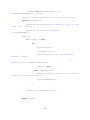
Simian Plus offers an easier method to replace the manual way of creating each of the
UAV elements in xml. After selecting the number of UAVs, the next screen displayed, can be
seen in the below figure. This page can be, used to specify the count of flying agents. Parameters
such as the position it should start from and velocity can be, entered using this screen. The below
screen gives the view on how the controller, that determines the manner a UAV should turn with,
to make a second sweep search can be configured.
19
Figure 5.4: Configure and Add Flying agents
5.1.3. Add boundaries
Each team has a limited area, within which the physical agents can fly. The dimensions
of this field is based on x, y and z co-ordinate axis. To describe the specifications of ‘area of
interest’ to the simian simulator, ‘policy.xml’ file is used. This file is manually, written using the
‘<policy>’ and ‘<boundaries> tag elements. This is now, replaced with the page/screen in figure
5.5. Simian Plus provides an easier method to state the boundary specifications voiding out one
of the many tedious jobs of scenario-description.
20
Figure 5.5: Add Boundaries
5.1.4. Add targets
In Simian, a target’s structure is, based on the model of type “sitting duck”. It has a
structure similar to the flying agent’s base model except that there is no hardware. The motion
parameters, referred as ‘limits’ are all set to zero, as the target is immobile i.e. it is a stationary
object in the field. In existing simian this is, described to the simulation processor using the
‘situation.xml’ file. Rewriting the xml structure for target using the same, structure as model can
be, observed here. Simian Plus, replaces this by displaying a screen that has user-friendly
interface, where the position of the target can be specified eliminating the input file format. User
can add a custom name for the ‘suiting duck’ base model and the team of the targets that belong
to it. Figure 5.6 is the screen that is, displayed in Simian Plus to add target’s location in a field.
Figure 5.6: Add Target Position
21
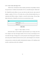
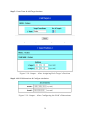
5.2. Mechanism to Launch New Scenario
After adding the UAVs and targets to the battle scenario, the next step would be
configuring the simulator specifications, for the client (Loislane) to communicate the
calculations to the server. This section illustrates the feature to pass the port number and other
such parameters. Processor calculations provide the systematic flight of the UAV to search and
destroy the target. Currently this is, described using the ‘global.xml’ file. Once again formatting
of elements and attributes that can be, interpreted by Simian are involved. Simian Plus voids this
process and instead displays the screen in figure 5.7, where simulator details can be, entered.
Figure 5.7: Simulator Specifications
Once the simulator is, assembled, clicking on “Create Configuration” creates the input
file that can be, interpreted by Simian. The xml processor is, triggered at this point. It processes
the input file and groups all the details like models, assigned teams based on each model, list of
UAVs, list of targets and the controllers for each of the available UAVs.
5.3. Mechanism to Launch Saved Scenario
This section refers to the feature, where any of the saved configurations can be launched
using the improvised system. Main page of the Simian Plus’s interface, displays two options
22
“Launch New” and “Launch Saved”. On clicking the “Launch Saved Configuration”, it displays
a screen with a dropdown, loaded with the configurations that were, saved earlier. Certain
frequently used scenario configurations can be, saved and re-used on demand. This saves time,
effort and redundancy of tasks.
Once the file is loaded, clicking “Run Simulation” will trigger the xml processor to
interpret the scenario configurations, which in turn invokes the client. The client (Loislane) then
communicates, with the server to visualize the mission.
5.4. Implementation
This section describes the implementation of the key features illustrated in the previous
section. As we have seen the various features that Simian Plus provides, it eases the entire
process of describing a scenario and configuring the agents involved. It plays a significant role in
keeping the user’s focus on formulating newer strategies instead of the repetitive problemdescription process. To implement the design goal of Simian Plus, JSP is used to the render the
user-friendly interface. Java, Servlets and Tomcat are, used as the backend technologies to create
the configuration file that can be, saved and launched for simulation. This interface has been,
developed using eclipse and a configured Tomcat server, to compile and access it, as a webapplication. All the files related to the Interface are placed in /WebContent folder of the simian
project.
The existing simian framework uses four different input files to describe the agents
involved in the simulation and specifications surrounding the strategy and area of interest. In the
new setup this is, replaced with just one file “situation.xml”. The layout of the configuration
details is, broadly divided into blocks of elements in the file. Below are the elements that serve
as the building blocks for creating a new scenario-description file.
23
Basic model
Team – associated team for each model.
Configurations/Position of each Unmanned Air Vehicle and Targets in each team.
Boundaries of each team
5.4.1. Model
Model is a template that holds the constraints related to the motion.
In
Simian, objects can be of two types, one UAV and the other, a target. Thus, model
is a basic structure for every agent that is invo lved in the simulation of a scenario.
It holds an attribute called “class” that distinguishes the type of object defined. It
contains an element called <limits> that holds the parameters like up acceleration,
speed and fuel capacity. Each UAV is, based on a model.
Files, that are used to create a basic model for a flying agent are ‘Model’,
Model_AddHardware’,‘Model_ConfigHardware’, XML_AddHardware, XML_ConfigHardware.
The limits would be upward acceleration, upward speed, downward acceleration, downward
speed, turn acceleration, forward acceleration, backward acceleration, speed and the fuel
capacity for an agent. If the agent is a physical/flying agent, then quantity of the hardware can
be, added. All the agents that are, based on the configured model will inherit the added
equipment.
Sensor range indicates the distance; a UAV can spot the target from. Here, the used
conical sensor class can be found in ‘orion.simian.things.sensors’. Half Angle denotes
an angle at which a sensor can spot a target at a given position.
24
Weapon corresponds to a missile carried by the UAV. Range speed and the blast
radius of the missile are, specified. The simple missile class can be found in
‘orion.simian.things’
Transmitter is the hardware that aids in transmitting a message to the environment
that handles all communication.
The commands issues are, received by the UAV with the help of sensors. The range
indicates the area/distance the UAV can receive the messages.
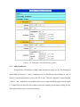
In Simian, ‘Situation.xml’ is, used for describing unmanned air vehicle and a targets
model. Below is the model–xml element structure, where the motion parameters and the
hardware configurations cluster can be, seen. The screen displayed in Simian Plus, that replaces
the manual creation of this file and automate xml creation can be, seen in figure 5.8. & figure
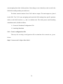
5.9. Here, the target positions screen, not only describes the whereabouts of its location but also
creates the model for ‘sitting duck’/targets using backend with one simple interface.
Screen displayed to automate the process of creating the xml:
Figure 5.8: Target Locations
25
Figure 5.9: Base Model and Hardware for UAVs
XML element in configuration file:
<model name='UAVModel1' class='uav' crashradius='10'>
<limits up_ac='1' up_sp='5' down_ac='3' down_sp='10'
back_ac='5' speed='50'
fuelCapacity='800' />
turn_ac='40.0'
fwrd_ac='4'
<transmitter class='rangedtransmitter' range='4000'/>
<receiver class='rangedreceiver' />
<sensor class='conicalsensor' range='200' halfangle='75'>0 0 -1 </sensor>
<weapon class='simplemissile' range='300' speed='500'
blastradius='50' />
<weapon class='simplemissile' range='300' speed='500'
blastradius='50' />
</model>
26
<model name='targetModel' class='sittingduck' crashradius='5'>
<limits up_ac='0' up_sp='0' down_ac='0' down_sp='0' turn_ac='0.0' fwrd_ac='0' back_ac='0'
speed='00' fuelCapacity='300' />
</model>
<team name='targetsTeam1'>
<smallthing model='targetModel'>
<position>-950 150 0</position>
<velocity>0 0 0</velocity>
</smallthing>
<smallthing model='targetModel'>
<position>-750 750 0</position>
<velocity>0 0 0</velocity>
</smallthing>
</team>
5.4.2. Team
Every model has a team. Every team has a set of unmanned air vehicles. Each UAV is
based on a model and has a controller. The agents are termed as 'small things' in the simian
world. For a UAV, position indicates the starting position in the field and velocity is the speed at
which the UAV should navigate in the mission. Controller is the element that determines the path
increment for a UAV. To calculate the path increment, ‘Start’, ‘Second’ and ‘End’ are the
parameters used. In other words, it determines the degree a UAV should turn before making the
second sweep search in the field.
'Model_ConfigHardware' is the file that handles the number of UAVs that are, added to
the mission which are, based on the newly configured model. Teams are, created for both, targets
and flying agents. This is, described to the current simian processor using “Situation.xml’ file.
27
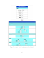
Information of the team formed and the assigned UAVs to it mentioned, by the tedious job of
manually writing the given below xml element. Simian Plus provides a feature that eases this
process and voids the human error in writing the file. Figure 5.10 denotes the screen displayed in
the enhanced system. It is, used for forming the teams and providing details related to each of the
agent/item with its location.
'UAV_AddAndConfig' corresponds to configure each of the UAVs starting with
position, velocity and the controller. All the mentioned configurations are, added to
the file that has been, created in the initial stages of "Launch New" step. The below
example shows that two UAV are added built on 'UAVModel1' model.
The velocity would be zero for the targets, as they are static in the field.
XML element created in configuration file:
<team name='DamnYankees'>
<smallthing model='targetModel'>
<position>-950 150 0</position>
<velocity>0 0 0</velocity>
</smallthing>
<smallthing model='targetModel'>
<position>-750 750 0</position>
<velocity>0 0 0</velocity>
</smallthing>
</team>
<team name='Twins'>
<smallthing model='UAVModel1' name='Rod'>
<position>-750 750 100</position>
28
<velocity>0 27 0</velocity>
</smallthing>
<smallthing model='UAVModel1' name='Harmon'>
<position>-800 750 100</position>
<velocity>0 27 0</velocity>
</smallthing>
</team>
Screen displayed to automate the process of creating the xml:
Figure 5.10: Team of Flying Agents and Targets
29
5.4.3. Boundaries
As mentioned in the earlier chapters, to describe the ‘area of interest’ to the
simian simulator, ‘policy.xml’ file is used. This file is manually, written using the
‘<policy>’ and ‘<boundaries> tag elements. The "aoi" is the tag, used for
representing the boundaries. It stands for 'Area of Interest'.
Every team of flying objects has a corresponding policy. The unmanned vehicles should
fly within the specified limits across the coordinate axis.
UAV_AddAndConfig' and 'XML_UAV' are the files used to display the view to prompt
the user to enter the start and the end, points of the field. Figure 5.11 shows the screen that is,
displayed where the boundaries for the team can be, stated with ease. Below is the snippet of
code, that formats the values entered and forms the xml element in the situation file.
str="bound1_1_"+(t+1);
b1=request.getParameter(str);
str="bound1_2_"+(t+1);
b2=request.getParameter(str);
str="bound1_3_"+(t+1);
b3=request.getParameter(str);
//second boundary
str="bound2_1_"+(t+1);
b4=request.getParameter(str);
str="bound2_2_"+(t+1);
b5=request.getParameter(str);
str="bound2_3_"+(t+1);
b6=request.getParameter(str);
30
//tags
tag="<policy team='"+tname+"' >";filedata+="\n"+tag;
tag="<aoi>";filedata+="\n"+tag;
tag="<bound>"+b1+""+b2+""+b3+"</bound>";filedata+="\n"+tag
tag="<bound>"+b3+""+b4+" +b5+"</bound>";filedata+="\n"+tag;
tag="</aoi>";filedata+="\n"+tag;
tag="</policy>";filedata+="\n"+tag;
XML element created in configuration file:
<policy team='UAVTeam1'>
<aoi>
<bound>-1000.0 -1000.0 -100.0</bound>
<bound>1000.0 1000.0 200</bound>
</aoi>
</policy>
Screen displayed to automate the process of creating the xml:
Figure 5.11: Dimensions of the Field
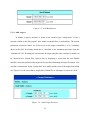
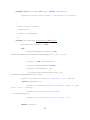
5.4.4. Simulation details
The field “port” corresponds to the port number to be , used by the client to
communicate with the class that visualizes the mission. In Simian, Vis2d is the
server that listens to the message commands from the Loislane (client) and
31
simulates the mission. 'Port', 'Hobbes', 'Filename' and 'feedback' are some of the
parameters. The ‘Loislane’ class holds. The time limit denotes span of time the
simulation should run for.
'Host' is an optional parameter that holds the port
number for a server connection to be established; if/incase the server is not started.
All these are, described to the simian using ‘Global.xml’ file. As pointed out in the
outlined challenges of simian, this has to be, written and formatted manually to
make sure that the simulation processor can interpret all the files without running
into errors and issues while visualizing.
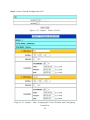
Below is the snippet of code that formats the specifications in Simian Plus. By default,
'seminar', 'hobbes', 'nofile' has the values set to align with the existing architecture of Simian
Framework. This piece corresponds to the 'global' details in the simian world. 'Simulator_Config'
and 'XML_Sim' are the files that are used to assemble the simulation specifications to an xml
element in ‘global’ file. Figure 5.12 shows the interface that corresponds to the mentioned
specifications. Once can see that the port number can be easily entered here eliminating the
process of ‘creating & running client’ as java application discussed in Chapter 2. It also voids the
process of manually passing the location of the newly created configuration file. This is
automated by the enhanced system, Simian Plus.
Snippet of code that creates model:
String filedata="",tag="";
tag="<global>";
filedata+="\n"+tag;
tag="<loislane
seminar=\"134.129.125.221\"
hobbes=\"192.168.125.25\"
port=\""+port+"\" delay=\"5\" winbox=\"192.168.125.21\" feedback='false'";
filedata+="\n"+tag;
if(cf.equals("Y"))
32
tag=" nofile='LoisLane.txt' />";
else
tag=" nofile='' />";
filedata+=tag;
tag="<simulator timestep='"+simtime+"' timelimit='"+timelimit+"'/>";
filedata+="\n"+tag;
tag="</global>";
filedata+="\n"+tag;
tag="</situation>";
filedata+="\n"+tag;
XML element created in configuration file:
<global>
<loislane seminar="134.129.125.221"hobbes="192.168.125.25"
port="9906" delay="10" winbox="192.168.125.21"
feedback='true' nofile='LoisLane.txt' />
<simulator timestep='0.40' timelimit='200' />
</global>
Screen displayed to automate the process of creating the xml:
Figure 5.12: Pass Port to Client (Loislane) & Simulation Details
33
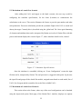
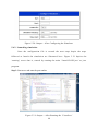
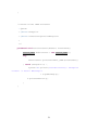
5.5. Validation
The Simulation-Graphical Interface has a feature that validates certain parameters that
are core in creating/running a scenario. These validators are easy to configure for different
behavior. Validators used in this interface evaluate if the user has entered a value for a specific
field. For every flying agent’s model, ‘turn’, ‘speed’, ‘fuel capacity’ and the ‘transmitter range’
needs to be, configured. Below is the snippet of java script that implements the validator used.
This interface has used only the “required fields” validator. Different types of validators are
available in “gen_validatorv4.js”. With the above format, they can all be, configured and used.
Below is the snippet that shows the validator, that validates the unmanned air vehicle’s motion
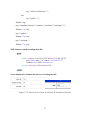
related parameters and the simulator specification’s validator. Figure 5.13 shows the highlighted
fields that are invalid by the corresponding validator.
Model – Validator:
<script type="text/javascript">
var frmvalidator = new Validator("f2");
frmvalidator.EnableOnPageErrorDisplay();
frmvalidator.EnableMsgsTogether();
//validator
frmvalidator.addValidation("turn", "req", "Please enter the turn parameter");
frmvalidator.addValidation("speed", "req", "Please enter speed");
frmvalidator.addValidation("cap", "req", "Please enter fuel capacity");
</script>
Simulation – Validator:
<script type="text/javascript">
var simValidator = new Validator("simForm");
34
simValidator.EnableOnPageErrorDisplay();
simValidator.EnableMsgsTogether();
simValidator.addValidation("port", "req", "Please enter the port");
simValidator.addValidation("simtime", "req", "Please enter time limit for
simulation");
simValidator.addValidation("timelimit", "req", "Please enter simulation time
limit");
//end of script
</script>
Figure 5.13: Invalid Fields Highlighted
5.6. Output – Scenario
This section illustrates the process for creating a new configuration file for scenarios
using ‘Sweep Search’. The sweep search suggested in this scenario is, based on controller
program implemented by the researches under the guidance of Dr. Kendall E. Nygard. The UAV
35
start navigating from their initial positions. State change occurs when they reach an end in the
field before making another pass on the area.
The below scenario consists of two UAVs and two targets. The static targets are, placed
in the field. Two UAVs start navigating and search the field starting from specific positions
relative to the field, based on x, y, and z co-ordinate axis. The whole process until launching
simulation can be, divided as follows:
Create the ‘Simulation/Configuration’ File
Launching Simulation
5.6.1. Create configuration file
The steps for creating a configuration file to simulate this scenario are, given
below.
Step 1: Construct and Configure Base Model.
36
Figure 5.14: Output – After Configuring the (UAV) Model
37
Step 2: Create a Team & Configure each UAV
Figure 5.15: Output – Team of UAVs
Figure 5.16: Output – After Assigning the UAVs Position and Configuring
Controllers
38
Step 3: Create Team & Add Target locations
Figure 5.17: Output – After Creating a Team of Targets
Figure 5.18: Output – After Assigning Each Target’s Position
Step 4: Add field dimensions & Configure simulation
Figure 5.19: Output – After Configuring the Field’s Dimensions
39
Figure 5.20: Output – After Configuring the Simulator
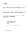
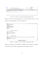
5.6.2. Launching simulation
Once the configuration file is created the next steps depict the steps
followed to launch the simulation are illustrated here. Figure 5.21 depicts the
‘running’ server that is, started by running the main ‘LaunchVis2D.java’ as java
program.
Step 1: Start server and enter the port number
Figure 5.21: Output – After Running the ‘Visualizer’
40
Figure 5.22: Output – After Successfully Opening the Port
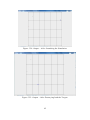
Step 2: Choose the created configuration file to launch simulation and click on “Run
Simulation”. SimianPlus displays a screen as in the figure 5.23
Figure 5.23: Output – After Creating the Configuration File
Step 3: On clicking the “Run Simualtion”, SimianPlus starts performing the calculation to
simualte the scenario. It displays a popup window, just like the figure 5.24 below
41
Figure 5.24: Output – After Launching the Simulation
Figure 5.25: Output – After Destroying both the Targets
42
6. CONCLUSION
This paper provides the design and the implementation of a Simian Plus that has various
features to enable a simpler process of ‘scenario-description’ to Simian. It describes the
technologies used to achieve the objectives paving way to a user-friendly Simian simulator. This
enables the researchers to easily create new scenarios/situations and focus more on building new
strategy to execute the mission instead. Mechanism to create new scenarios, ability to start and
run the application, ability to save and launch the previously configured scenarios can all
achieved by following the user intuitive interface. We have seen the basic validation that is
included on the interface, which requires certain values/parameters to be entered. Simian Plus
aids in not just creating scenarios but also in running them by minimizing human error in
formulating the input file. Default values are plugged in, to create a valid configuration file. With
the below flexible features, it thus aligns to the one of the main principle of simian where
problem description is separate from the strategy of executing a mission.
Summary of Features:
Mechanism to build a base model for the flying agents
Build/configure hardware for each UAV
Place targets
Create new scenarios with different combinations of hardware and agents
Launch the newly created scenario
Launch the saved/previous scenarios.
43
7. FUTURE WORK
7.1. Search Strategy
Search strategy refers to the patterns of investigating the area of interest/field to detect the
targets. Simian Plus uses ‘Sweep search’ pattern i.e. the unmanned air vehicles start from one
corner of the field and travel towards the horizontal end of the grid, turn and continue to the
other end of the next horizontal grid. A feature that displays various other patterns that simian
offers, such as Hunter and Killer UAVs and Forward Air Control search would enable the user to
choose the specific search strategy to execute the mission
7.2. Enhance Validation
Currently all the fields, are validated to verify if the user has entered the values for it.
This validation can be further, enhanced to validate the values entered. For example, verifying
the validity of values such as speed, blast radius of a weapon, receiver’s range limit, swath etc.
entered by the user during the hardware configuration process.
44
8. REFERENCES
[1] Altenburg, Karl, Joseph Schlecht, and Kendall E. Nygard, An Agent-based Simulation for
Modeling Intelligent Munitions in Proceedings of the Second WSEAS Int. Conf. on Simulation,
Modeling and Optimization, Skiathos, Greece, 2002.
[2] M. Hennebry, “Quickstart Guide to the Simian Simulator”, Department of Computer Science,
NDSU.
[3] Rachid Alami, Raja Chatila and Hajime Asama, Distributed Autonomous Robotic Systems 6
[4] Yaniv Altshuler, Vladimir Yanovsky, Israel A. Wagner, and Alfred M.Bruckstein, “The
Cooperative Hunters —Efficient Cooperative Search For Smart Targets Using UAV Swarms”,
Computer Science Department, Technion, Haifa 32000 Israel.
[5] Ivan Maza and Anibal Ollero, “Multiple UAV cooperative searching operation using polygon
area decomposition and efficient coverage algorithms”, University Of Seville, 41092 Seville,
Spain
[6] Yan Jin, Ali A. Minai, Marios M. Polycarpou, “Cooperative Real-Time Search and Task
Allocation in UAV Teams”, University of Cincinnati, OH 45221-0030.
[7] Randal W. Beard, Timothy W. McLain, “Multiple UAV Cooperative Search under Collision
Avoidance and Limited Range Communication Constraints”, Brigham Young University,
Electrical and Computer Engineering, Provo, Utah 84602.
[8] Altenburg, Karl, M. Hennebry, J. Pikalek and Kendall E. Nygard, “Simian: A Multi-agent
Simulation Framework for Decentralized UAV Task Allocation
[9]http://help.eclipse.org/indigo/index.jsp?topic=%2Forg.eclipse.jst.ws.axis.ui.doc.user%2Ftopic
s%2Fttomcatserv.html
45
APPENDIX A. LAUNCH SIMULATION SERVLET PROGRAM
package util;
import java.io.File;
import java.io.IOException;
import java.net.InetAddress;
import java.net.InetSocketAddress;
import java.net.ServerSocket;
import java.util.HashMap;
import java.util.Map;
import javax.servlet.http.HttpServlet;
import javax.servlet.http.HttpServletRequest;
import javax.servlet.http.HttpServletResponse;
import javax.xml.parsers.ParserConfigurationException;
import org.dom4j.Document;
import org.dom4j.DocumentException;
import org.dom4j.Element;
import org.dom4j.io.SAXReader;
import orion.simian.drivers.Launch_DXML;
@SuppressWarnings("serial")
public class LaunchSimServlet extends HttpServlet {
protected void doPost(HttpServletRequest req, HttpServletResponse
res){
46
Map<String, String> messages = new HashMap<String,
String>();
Map<String, String> errors = new HashMap<String, String>();
ServerSocket listener = null;
Element simDoc = null;
String configFileName = null;
configFileName = (String)
req.getSession().getAttribute("name");
String serverPortStr = req.getParameter("serverPort");
try{
//loadDocument
simDoc = processFile(configFileName);
//extractPort
if(serverPortStr == null){
serverPortStr = extractPort(simDoc);
}
//startProcessor
startProcessor(simDoc);
}catch(DocumentException de1){
System.out.println("Exception :"+de1.getMessage());
de1.printStackTrace();
}
}
47
private Element processFile(String fileName) throws
DocumentException {
File file = new File(fileName);
Document docFile=(new SAXReader()).read(file);
Element rootEl = docFile.getRootElement();
return rootEl;
}
/**Process file and extract value
*
@param fileName
*
return value
* **/
private String extractPort(Element root){
Element el1 = root.element("global");
Element lois = el1.element("loislane");
String value = lois.attributeValue("port");
return value;
}
@SuppressWarnings("unused")
private boolean validatePort(int port){
ServerSocket listener = null;
boolean isValid = false;
try{
48
listener=new ServerSocket(port, 50,
InetAddress.getByName("0.0.0.0"));
System.out.println("Connection Succesful. Port :"+port);
}catch(IOException e){
System.out.println("Connection Refused. Could not open
server, Port ::"+port);
System.out.println("Detail message
::"+e.getMessage());
}finally{
if(listener != null){
try {
killSocket(port);
//listener.close();
System.out.println("Killing Connection
succefull :"+port +
" \n
Listener status" +listener.isClosed());
isValid = true;
} catch (IOException e) {
System.out.println("Exception occured while
closing the socket port :"+port);
e.printStackTrace();
}
}
System.out.println("Exitting");
}
return isValid;
}
49
private void killSocket(int port) throws IOException {
System.out.println("killSocket(): Releasing port "+port);
}
/**Start Server Listener
* @param port
* return serverSocket
**/
private ServerSocket startServer(int port){
ServerSocket listener = null;
try{
InetSocketAddress address = new
InetSocketAddress(InetAddress.getByName("0.0.0.0"), port);
listener = new ServerSocket();
listener.setReuseAddress(true);
listener.bind(address, 10);
//listener=new ServerSocket(port, 50,
InetAddress.getByName("0.0.0.0"));
System.out.println("Connection Succesful. Port :"+port);
}catch(IOException e){
System.out.println("Connection Refused. Could not open
server, Port ::"+port);
System.out.println("Detail message
::"+e.getMessage());
System.out.println("Killing the listner ::");
}
return listener;
50
}
/**Invoke Client DXML Processor
* @param
* @throws Exception
* @throws ParserConfigurationException
*
**/
protected void startProcessor(Element rootElement){
Launch_DXML xmlProcessor = new Launch_DXML();
try{
xmlProcessor.processDocument_DXML(rootElement);
} catch (Exception e) {
System.out.println("startProcessor(): Exception
occured. \n Detail Maessage:"
+ e.getMessage());
e.printStackTrace();
}
}
51
APPENDIX B. LAUNCH_VIS2D SERVER PROGRAM
package orion.simian.util ;
import java.awt.Color;
import java.awt.Dimension;
import java.awt.Graphics;
import java.awt.Insets;
import java.awt.event.WindowAdapter;
import java.awt.event.WindowEvent;
import java.io.BufferedReader;
import java.io.IOException;
import java.io.InputStreamReader;
import java.io.PrintStream;
import java.net.InetAddress;
import java.net.ServerSocket;
import java.net.Socket;
import java.net.UnknownHostException;
import java.util.ArrayList;
import java.util.ListIterator;
import javax.swing.JFrame;
import orion.simian.util.Vector3D;
public class Launch_Vis2D {
static final int UAV=1;
static final int SITTINGDUCK=2;
static final Color darkGreen=new Color(0.0f, 0.5f, 0.0f);
52
public static void main(String[] args){
String input = null;
Launch_Vis2D vis2D = null;
ServerSocket listener = null;
TrackThreads tracker = new TrackThreads();
BufferedReader br = new BufferedReader(new
InputStreamReader(System.in));
System.out.println("Enter the port :");
try {
input = br.readLine();
} catch (IOException e) {
System.out.println("Launch_Vis2d(): Invalid Port
\n"+e.getStackTrace());
System.exit(1);
}
if(input != null || input!= ""){
int port = Integer.parseInt(input);
try {
listener = new ServerSocket(port,10,
InetAddress.getByName("0.0.0.0"));
System.out.println("Launch_Vis2d(): Sucessful in
opening the port."+listener.getLocalSocketAddress());
} catch (UnknownHostException e1) {
System.out.println("Launch_Vis2d(): Issue in
opening the port.\n"+e1.getStackTrace());
System.exit(1);
53
} catch (IOException e2) {
System.out.println("Launch_Vis2d(): IO Issue in
opening the port.\n"+e2.getStackTrace());
System.exit(1);
}
}
while(true){
SocketThread thread = null;
try {
Socket sock = listener.accept();
thread = new SocketThread(sock);
thread.start();
tracker.updateCount(1, thread);
System.out.println("Launch_Vis2d(): Sucessful in
creating a thread. \n Client Details: "+thread.toString());
} catch (IOException e) {
System.err.println("Launch_Vis2d(): Client
accept failed " +e.getStackTrace());
System.exit(3);
}
if (vis2D != null && vis2D.painter != null) {
vis2D.painter.dispose();
}
54
vis2D = new Launch_Vis2D();
System.out.println("Launch_Vis2d(): About to
visualize. ");
vis2D.run(thread);
try {
thread.csocket.close();
thread.interrupt();
} catch (IOException e) {
System.out.println("Launch_Vis2d(): Unsucessful
in closing the port for thread. \n Socket LocalAddress
:"+thread.getName());
}
}
}
static class STD {
Vector3D position, fwrd;
int kind;
boolean live;
STD(STD src) {
position=new Vector3D(src.position);
fwrd=new Vector3D(src.fwrd);
live=src.live;
kind=src.kind;
}
55
STD() {
position=new Vector3D();
fwrd=new Vector3D(1, 0, 0);
live=true;
kind=UAV;
}
} // STD
ArrayList paintable=new ArrayList(), backup=new ArrayList();
double axlo, axhi, aylo, ayhi;
double
xlo,
xhi,
ylo,
yhi;
static final int slop=10;
static final long period=1000;
long nextPaintTime=0;
// milliseconds
// milliseconds
boolean painted=false;
class Painter extends JFrame {
public boolean done=false;
Painter() { setSize(500, 500); show(); }
Graphics graphics=null;
public void paint() { if(null != graphics) paint(graphics); }
public void paint(Graphics g)
56
{
nextPaintTime=System.currentTimeMillis()+period;
graphics=g;
if(axlo>=axhi || aylo>=ayhi) return;
Insets insets=getInsets();
Dimension size=getSize();
g.clearRect(0, 0, size.width, size.height);
for(ListIterator it=paintable.listIterator();
it.hasNext(); ) {
STD fred=(STD)it.next();
if(fred != null) {
if(fred.position.x< xlo) xlo=fred.position.x;
if(fred.position.x> xhi) xhi=fred.position.x;
if(fred.position.y< ylo) ylo=fred.position.y;
if(fred.position.y> yhi) yhi=fred.position.y;
}
} // it
double xscale=(size.width-insets.left-insets.right-2*slop)
/(xhi-xlo);
double yscale=(size.height-insets.top-insets.bottom2*slop)
/(yhi-ylo);
double scale=xscale;
if(yscale< scale) scale=yscale;
if(scale<=0) return;
57
double xoffset=(size.width +
insets.left-insets.rightscale*(xlo+xhi))/2.0;
// y scaled with -scale
double yoffset=(size.height +
insets.topinsets.bottom+scale*(ylo+yhi))/2.0;
for(ListIterator it=paintable.listIterator();
it.hasNext(); ) {
STD fred=(STD)it.next();
if(fred==null) continue;
double xc=xoffset+scale*fred.position.x;
double yc=yoffset-scale*fred.position.y;
if(fred.kind==UAV) {
double xp=xc+8*fred.fwrd.x;
double yp=yc-8*fred.fwrd.y;
double xl=xc-5*fred.fwrd.x-5*fred.fwrd.y;
double xr=xc-5*fred.fwrd.x+5*fred.fwrd.y;
double yl=yc+5*fred.fwrd.y-5*fred.fwrd.x;
double yr=yc+5*fred.fwrd.y+5*fred.fwrd.x;
int x [] = { (int)xc, (int)xl, (int)xp, (int)xr }
;
int y [] = { (int)yc, (int)yl, (int)yp, (int)yr }
;
if(fred.live) g.setColor(Color.blue);
58
else
g.setColor(Color.gray);
g.drawPolygon(x, y, x.length);
/*------------g.drawLine((int)(xc-4), (int)yc,
(int)(xc+4), (int)(yc) );
g.drawLine((int)xc, (int)(yc-4),
(int)xc, (int)(yc+4) );
*/
} else {
if(fred.live) g.setColor(Color.red);
else
g.setColor(Color.black);
g.drawLine((int)(xc-4), (int)(yc-4),
(int)(xc+4), (int)(yc+4) );
g.drawLine((int)(xc-4), (int)(yc+4),
(int)(xc+4), (int)(yc-4) );
}
} // it
{
int xlo2=(int)(scale*axlo+xoffset);
int xhi2=(int)(scale*axhi+xoffset);
int ylo2=(int)(scale*aylo+yoffset);
int yhi2=(int)(scale*ayhi+yoffset);
g.setColor(Color.white);
59
int x[] = { xlo2, xlo2, xhi2, xhi2 } ;
int y[] = { ylo2, yhi2, yhi2, ylo2 } ;
g.drawPolygon(x, y, x.length);
g.setColor( Color.black );
int col_inc = (xhi2-xlo2)/6 ;
int row_inc = (yhi2-ylo2)/4 ;
for ( int i = xlo2; i <= xhi2 ; i+=col_inc )
{
g.drawLine( i ,ylo2 , i, yhi2 );
}
for ( int j = ylo2; j <= yhi2 ; j+=row_inc )
{
g.drawLine( xlo2, j ,xhi2, j );
}
}
painted=true;
} // paint
} // Painter
Painter painter;
private void run(SocketThread st) {
60
BufferedReader br = null;
PrintStream pstream = null;
try {
br = new BufferedReader(new
InputStreamReader(st.csocket.getInputStream()));
pstream = new
PrintStream(st.csocket.getOutputStream());
runSimulation(br, pstream);
} catch (IOException e) {
System.out.println("Launch_Vis2d(): Error in
running simulation for Client-Thread : "+st.csocket.toString());
e.printStackTrace();
} catch (InterruptedException e) {
System.out.println("Launch_Vis2d(): Interruption in
running simulation for Client : "+st.csocket.toString());
e.printStackTrace();
}
System.out.println("Launch_Vis2d():Client is connected"
+st.csocket.toString());
}
/**
* @param fin
* @param fout
* @throws IOException
* @throws InterruptedException
*/
private void runSimulation(BufferedReader fin, PrintStream fout)
61
throws IOException, InterruptedException {
int stIndex=0;
STD std=null;
painter=new Painter();
painter.addWindowListener(
new WindowAdapter() {
public void windowClosing(WindowEvent e) {
painter.done=true;
System.out.println("painter.done=true");
}
}
) ;
String line;
while(!painter.done && (line=fin.readLine())!=null) {
line=line.trim();
String tokens [] = line.split("
*");
if(tokens.length==0 || tokens[0].length()==0) continue;
if("TICK".equals(tokens[0])) {
ArrayList tmp=backup;
backup=paintable;
paintable=tmp;
painted=false;
painter.repaint();
if(System.currentTimeMillis()>=nextPaintTime) {
for(int j=1; !painted; j+=j) Thread.sleep(j);
}
62
fout.println(line);
for(int j=backup.size()-1; j>=0; --j) {
backup.set(j, new STD((STD)paintable.get(j)));
}
// make backup a deep copy of paintable
while(backup.size()< paintable.size()) {
backup.add(new
STD((STD)paintable.get(backup.size())));
}
} else if("AOI".equals(tokens[0])) {
axlo=Double.parseDouble(tokens[1]);
aylo=Double.parseDouble(tokens[2]);
axhi=Double.parseDouble(tokens[4]);
ayhi=Double.parseDouble(tokens[5]);
if(axlo> axhi) { double tmp=axlo; axlo=axhi;
axhi=tmp; }
if(aylo> ayhi) { double tmp=aylo; aylo=ayhi;
ayhi=tmp; }
xlo=axlo; xhi=axhi;
ylo=aylo; yhi=ayhi;
} else if("UAV".equals(tokens[0])) {
stIndex=Integer.parseInt(tokens[1]);
while(backup.size()<=stIndex) backup.add(null);
if(backup.get(stIndex)==null) {
backup.set(stIndex, new STD());
}
63
std=(STD)backup.get(stIndex);
std.kind=UAV;
} else if("SITTINGDUCK".equals(tokens[0])) {
stIndex=Integer.parseInt(tokens[1]);
while(backup.size()<=stIndex) backup.add(null);
if(backup.get(stIndex)==null) {
backup.set(stIndex, new STD());
}
std=(STD)backup.get(stIndex);
std.kind=SITTINGDUCK;
} else if("DEAD".equals(tokens[0])) {
int j=Integer.parseInt(tokens[1]);
if(0<=j && j< backup.size())
{ ((STD)backup.get(j)).live=false; }
} else if("POSITION".equals(tokens[0])) {
double x=Double.parseDouble(tokens[1]);
double y=Double.parseDouble(tokens[2]);
double z=Double.parseDouble(tokens[3]);
std.position.setTo(x, y, z);
} else if("FORWARD".equals(tokens[0])) {
double x=Double.parseDouble(tokens[1]);
double y=Double.parseDouble(tokens[2]);
double z=Double.parseDouble(tokens[3]);
std.fwrd.setTo(x, y, z);
} else if("ECHO".equals(tokens[0])) {
painted=false;
64
painter.repaint();
for(int j=1; !painted ; j+=j) Thread.sleep(j);
fout.println(line);
}
} // while
}
}
65
APPENDIX C. LAUNCH_DXML PROCESSOR PROGRAM
package orion.simian.drivers;
import java.io.File;
import java.util.LinkedList;
import java.util.List;
import java.util.ListIterator;
import javax.xml.parsers.ParserConfigurationException;
import org.dom4j.Document;
import org.dom4j.DocumentException;
import org.dom4j.Element;
import org.dom4j.io.SAXReader;
import orion.simian.Environment;
import orion.simian.things.SittingDuck;
import orion.simian.things.SmallThing;
import orion.simian.things.SmallThings;
import orion.simian.util.Controllee;
import orion.simian.util.Controller;
import orion.simian.util.Launch_Loislane;
import orion.simian.util.LoisLane;
import orion.simian.util.NamedStrings;
import orion.simian.util.Strings;
import orion.simian.util.Vector3D;
import orion.simian.util.VisualizerMsg;
66
import orion.simian.util.WantsReporter;
import orion.simian.util.Xml;
public class Launch_DXML {
interface simConstants extends Strings, NamedStrings {}
interface s extends Strings, NamedStrings {}
public Launch_DXML() {
//super;
}
public Launch_DXML(String str) throws
ParserConfigurationException, DocumentException {
File _file = new File(str);
Document doc=(new SAXReader()).read(_file);
System.out.println ("Root element of the doc is " +
doc.getName());
//processDocument(doc);
//processDocument_DXML(doc);
}
public void processDocument_DXML(Element rootEl){
//rootElement
System.out.println("Root name is "+ rootEl.getName());
List<Element> simElList = new LinkedList<Element>();
67
simElList.add(rootEl);
List strategys=new LinkedList();
strategys.add(rootEl.element("strategy"));
Xml.printElementList("strategaaay", strategys);
List globals=new LinkedList();
globals.add(rootEl.element("global"));
Xml.printElementList("globalll", globals);
List policys=new LinkedList();
policys.add(rootEl.element("policy"));
Xml.printElementList("policyyyy", policys);
List gmodels=Xml.selectNodes(s.model, simElList);
Xml.printElementList("gmodels", gmodels);
List teams=Xml.selectNodes(s.team, simElList);
Xml.printElementList("teams", teams);
SmallThings allSmallThings=new SmallThings();
for(ListIterator tit=teams.listIterator(); tit.hasNext();
// one iteration for each team
Element team=(Element)tit.next();
String teamNm=team.attributeValue(s.name, null);
68
) {
List teamPids=team.selectNodes(s.smallthing);
List teamPmodels=new LinkedList();
teamPmodels.addAll(team.selectNodes(s.model));
teamPmodels.addAll(gmodels);
Element policy=(Element)Xml.selectSingleNode(
"." + s.LSB + "@" + s.team + "=" +
s.QQUOTE + teamNm + s.QQUOTE + s.RSB,
policys, true );
for(ListIterator stit=teamPids.listIterator();
stit.hasNext();
) {
// one iteration per small thing on team
Element pid=(Element)stit.next();
String modelNm=pid.attributeValue(s.model, null);
if(null==modelNm) {
throw new Error("smallthing has no model:\n" +
pid.asXML() );
}
// the model of the current small thing
Element pmodel=(Element)Xml.selectSingleNode(
"." + s.LSB + "@" + s.name + "=" +
s.QQUOTE + modelNm + s.QQUOTE + s.RSB,
teamPmodels, false );
// the making of different kinds of small things
// is a job for a factory in SmallThing
SmallThing smallThing=
SmallThing.make(pid, teamPmodels, globals);
69
System.out.println("transmitters:\n" +
smallThing.transmitters);
System.out.println("receivers:\n" +
smallThing.receivers);
if(smallThing instanceof Controllee) {
String stNm=pid.attributeValue(s.name, null);
if(null==stNm) {
throw new Error(
"smallthing has no name:\n" +
pid.asXML() );
}
// the Element containing the
// controllers for this smallthing
Element controllersEl=(Element)
Xml.selectSingleNode(
s.controllers + s.LSB + "@" + s.name + "="
+
s.QQUOTE + stNm + s.QQUOTE + s.RSB,
strategys );
if(null==controllersEl) {
throw new Error(
"Controllee " + stNm + " has no
controllers" );
}
final String
vehicleClassNm="orion.simian.vehicle.Vehicle";
List controllerEls=controllersEl.elements();
Controller prevController=null;
70
try {
final Class
liClass=Class.forName("java.util.List");
final Class elClass=Class.forName(
"org.dom4j.Element" );
//
constructor signature
final Class [] conSig= {
elClass, elClass, liClass,
elClass, elClass,
liClass, liClass };
for(ListIterator
cit=controllerEls.listIterator();
cit.hasNext();
) {
Element controllerEl=(Element)cit.next();
String classNm=
controllerEl.attributeValue("class", null);
if(s.vehicle.equals(classNm))
{ classNm=vehicleClassNm; }
if(null==classNm) {
if(s.vehicle.equals(controllerEl.getName())) {
classNm=vehicleClassNm;
} else {
throw new
Error("controller has no
class\n:" +
71
controllerEl.asXML() );
}
}
Class
controllerClass=Class.forName(classNm);
Object [] parms={
pid, pmodel, globals,
controllerEl, policy,
teamPids, teamPmodels
} ;
java.lang.reflect.Constructor constructor=
controllerClass.getConstructor(conSig);
// the new controller
Object
controllerO=constructor.newInstance(parms);
if(! (controllerO instanceof Controller)) {
throw new Error("class " + classNm +
" is not a Controller"
);
}
if(null != prevController) {
if(!(controllerO instanceof Controllee)
) {
72
throw new Error("class " + classNm
+
" is not a
Controllee" );
}
((Controllee)controllerO).
setController(prevController);
}
prevController=(Controller)controllerO;
} // cit
((Controllee)smallThing).setController(prevController);
} catch(Exception e) {
throw new Error(e);
}
}
allSmallThings.add(smallThing);
} // stit
} // tit
Environment env=new Environment();
env.fred=allSmallThings;
Vector3D bound1=null;
Vector3D bound2=null;
try {
List boundEls=Xml.selectNodes("aoi/bound", policys);
73
ListIterator it=boundEls.listIterator();
bound1=new Vector3D((Element)it.next());
bound2=new Vector3D((Element)it.next());
} catch(Exception e) {
throw new Error(e);
}
// Process Loislane
//LoisLane rep = null;
Launch_Loislane rep = null;
Element loislaneEl = (Element)
Xml.selectSingleNode("loislane", globals);
if (loislaneEl != null) {
//rep = new LoisLane(loislaneEl);
rep = new Launch_Loislane(loislaneEl);
} else {
throw new Error("Error: LoisLane Element not found.");
}
env.reporter=rep;
env.reporter.report(new VisualizerMsg("AOI " +
bound1.x + s.blank + bound1.y + s.blank + bound1.z +
s.blank +
bound2.x + s.blank + bound2.y + s.blank + bound2.z ));
for(int j=0; j< env.fred.size(); ++j) {
if(env.fred.get(j) instanceof SittingDuck) {
SittingDuck sd=(SittingDuck)env.fred.get(j);
74
env.reporter.report(new VisualizerMsg("SITTINGDUCK " +
j));
env.reporter.report(new VisualizerMsg("POSITION " +
sd.position.x + s.blank +
sd.position.y + s.blank +
sd.position.z ));
}
if(env.fred.get(j) instanceof WantsReporter) {
((WantsReporter)env.fred.get(j)).setReporter(rep);
}
} // j
Element simulatorEl=(Element)Xml.selectSingleNode("simulator",
globals);
double timeStep=Xml.getDoubleAttribute(simulatorEl,
s.timestep);
double timeLimit=Xml.getDoubleAttribute(simulatorEl,
"timelimit");
env.loop(timeLimit, timeStep);
try {
rep.shutdown();
} catch(Throwable t) {
throw new Error(t);
}
}
}
75