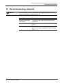
1
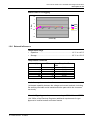
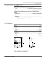
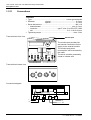
sheet 522
&5B6%
Solid state single phase meter
User manual
User manual S2AS-100 / 200 Solid State Single Phase Meter
Introduction
Introduction
Range of validity
The present user manual applies to the basic version of the meters:
• S2AS-100
(for single phase two wire system with installer switch)
• S2AS-200
(for single phase two wire system without inst. switch)
Explanations without specific type details apply to both types.
Purpose
The user manual contains all the information required for application of the
meters for the intended purpose. This includes:
• Provision of knowledge concerning characteristics, construction and
function of the meters
• Information about possible dangers, their consequences and measures
to prevent any danger
• Details concerning the performance of all work throughout the service
life of the meters (parametrizing, installation, commissioning, operation,
maintenance, shutting down and disposal)
Target group
The contents of this user manual are intended for technically qualified personnel of energy supply companies responsible for the system planning,
installation and commissioning, operation, maintenance, decommissioning
and disposal of the meters.
Conditions
The user of this manual has received instruction in basic electrical principles, in particular the various principal types of circuit for energy measurement.
Subdivision
This user manual is divided in a logical manner suitable for learning and
application, i.e. the individual chapters follow the sequence of information
probably required during the various phases of the service life of the meters. This provides the following structure:
• Chapter 1
Description of unit
• Chapter 2
Safety
• Chapter 3
Construction and Function
• Chapter 4
Control elements and displays
• Chapter 5
Programming / Interrogation Interface
• Chapter 6
Installation and commissioning
• Chapter 7
Data readout
• Chapter 8
Metering testing
• Chapter 9
Detection of faults
• Chapter 10 Decommissioning, disposal
Siemens Metering AG
H 71 0200 0015 en 1st edition
0-3
User manual S2AS-100 / 200 Solid State Single Phase Meter
Table of contents
Table of contents
0-4
1
1.1
1.1.1
1.1.2
1.2
1.2.1
1.2.2
1.2.3
1.2.4
1.2.5
1.2.6
1.2.8
1.2.9
1.2.10
1.2.11
Description of unit........................................................................ 1
Review............................................................................................ 1
General Review.............................................................................. 1
Type designation ............................................................................ 2
Technical Data ............................................................................... 3
Voltage Values ............................................................................... 3
Current Values ............................................................................... 3
Frequency values ........................................................................... 4
Power Consumption ....................................................................... 4
Measuring accuracy ....................................................................... 4
External influences ......................................................................... 5
Output Values................................................................................. 6
Opto- Interface according IEC 1107............................................... 7
Dimensions..................................................................................... 7
Connections ................................................................................... 8
2
2.1
2.2
2.3
Safety............................................................................................. 1
Safety information .......................................................................... 1
Responsibilities .............................................................................. 1
Safety regulations........................................................................... 2
3
3.1
3.2
3.2.1
3.3
3.4
3.5
3.5.1
3.5.2
3.5.3
3.5.4
3.6
Construction and Function ......................................................... 1
Metering Principle........................................................................... 1
Reset and Initialisation ................................................................... 2
Normal Reset ................................................................................. 2
Power Down Operation .................................................................. 2
Memory Access.............................................................................. 3
Metering ......................................................................................... 3
Register Model ............................................................................... 3
Auxiliary input terminal ................................................................... 4
Total Register ................................................................................. 4
Active Rate selection...................................................................... 4
Configuration File ........................................................................... 4
4
4.1
4.1.1
4.1.2
4.1.3
4.1.4
4.2
4.2.1
4.2.2
4.3.1
4.3.2
Control elements and displays ................................................... 1
LCD Display ................................................................................... 1
Display specification....................................................................... 1
Normal Displays ............................................................................. 1
Dial Checks .................................................................................... 2
Annunciators .................................................................................. 2
Switch Control ................................................................................ 2
SAS-100 ......................................................................................... 2
S2AS-200 ....................................................................................... 3
Tariff ID........................................................................................... 3
Meter Serial Number ...................................................................... 3
Siemens Metering AG
H 71 0200 0015 en 1st edition
User manual S2AS-100 / 200 Solid State Single Phase Meter
Introduction
5
5.1
Programming / Interrogation Interface .......................................1
Optical Communication Port ...........................................................1
6
6.1
6.2
6.3
6.4
6.5
6.6
Installation and commissioning ..................................................1
Introduction .....................................................................................1
Material and tools required .............................................................1
Mounting the meter.........................................................................2
Connecting meter ...........................................................................3
Check of connections .....................................................................3
Commissioning and functional check .............................................4
7
Data readout..................................................................................1
8
8.1
8.2
Meter Testing ................................................................................1
Calibration link ................................................................................1
Calibration LED Output...................................................................1
9
9.1
9.2
9.3
9.4
9.5
9.6
9.7
9.8
Detection of faults ........................................................................1
Error Messages ..............................................................................1
Tamper / Fraud ...............................................................................1
Watchdog and Exception Handling.................................................1
Reverse Detect ...............................................................................1
Creep ..............................................................................................1
Mains Failure ..................................................................................2
Failure Tolerance............................................................................2
Energy Register Locking.................................................................2
10
Decommissioning, disposal ........................................................1
Siemens Metering AG
H 71 0200 0015 en 1st edition
0-5
User manual S2AS-100 / 200 Solid State Single Phase Meter
Description of unit
1
Description of unit
1.1
Review
1.1.1 General Review
View of meter:
IEC1107
Interface
BS compliant
Terminal
Fig.1
General view of meter
Residential metering
The S2AS meters form a family of solid state single phase meters to cover
the whole range of residential metering applications. Single or two rate
register, pulse output and communcation interface according IEC 1107.
The meters can be used for currents up to 100 A.
The meter is equipped with features to enable the detection of fraud
attempts. The meter has a reverse energy register as well as a register
recording the number of power-on hours it sees.
A unique feature is the low power consumption which helps to reduce the
network losses
Modular design
The meter fulfils the requirements of today’s metering practice, while the
design concept is already prepared to cope with tomorrow’s needs in a fully
liberalised market. Future requirements can be realised in the form of
external circuits incorporated in a module unit that can be adapted to the
basic meter (adaptive meter concept).
Siemens Metering AG
H 71 0200 0015 en 1st edition
1-1
User manual S2AS-100 / 200 Solid State Single Phase Meter
Description of unit
Case
The meter is housed in a polycarbonate case designed for the easy fitting
of add-on modules. Through its small size and low weight the S2AS meter
saves costs in logistics.
1.1.2 Type designation
S2AS-100
Module port
Meter with installer switch
The installer switch allows
the supply to the premises to
be disconnected without
drawing the main fuse or
disconnecting cables
S2AS-200
Meter without installer switch
Module port
1-2
Siemens Metering AG
H 71 0200 0015 en 1st edition
User manual S2AS-100 / 200 Solid State Single Phase Meter
Description of unit
1.2
Technical Data
1.2.1 Voltage Values
Rated Voltage
•
•
Nominal as per IEC 61036.................................................... 230V + 10%
Range for mains input voltages ................................. 0.8 up to 1.15 x Un
Note:
1. The meter is fully operational within 4 seconds of the application of a
voltage supply in the above range
2. The meter will power down and inhibit all operations if the mains
voltage falls below 150VAC.
3. Between ISO V and 184 V operation is not guaranteed, however the
meter will not malfunction, corrupt stored data or register spurious
consumption and will power up or down cleanly once the mains input
voltage rises above or below these values.
4. The requirements specified in 2 and 4 above, are independent of the
rate of change of the mains input voltage.
5. The meter will remain operational for mains voltage interruptions of up
to 0.2 seconds. For interruptions of greater than 0.2 seconds, the meter
may power down and up again but shall do so without malfunction,
corrupting data or registering spurious electricity consumption.
1.2.2 Current Values
Basic current Ib ................................................................either 10A or 20A
Maximum Current Imax ..................................................either 80A or 100A
Maximum measuring range ...........up to 120A without exceeding 5% error
Creep inhibit circuit operating ............................... at approximately 40mA
Note: Current sensing is by means of a shunt.
Siemens Metering AG
H 71 0200 0015 en 1st edition
1-3
User manual S2AS-100 / 200 Solid State Single Phase Meter
Description of unit
1.2.3 Frequency values
Rated frequency ...................................................................................50Hz
1.2.4 Power Consumption
•
voltage circuit burden .............. less than 0.5W and 9VA. Typically 0.4 W
•
VA burden of the current circuit at Imax ..........less than 0.25W / 0.25 VA
1.2.5 Measuring accuracy
Accuracy
•
Accuracy class to IEC 61036 ........................................................ class 2
Unity Power Factor at 20°C environmental temperature
1.5
1
% Error
0.5
0
0
20
40
60
80
100
-0.5
-1
-1.5
Current (A)
Unity power factor
1.5
1
% Error
0.5
253v
0
220v
0
20
40
60
80
100
198v
-0.5
-1
-1.5
Current (A)
1-4
Siemens Metering AG
H 71 0200 0015 en 1st edition
User manual S2AS-100 / 200 Solid State Single Phase Meter
Description of unit
Power Factor = 0.5 Lagging
1.5
1
% Error
0.5
253v
220v
0
0
20
40
60
80
100
198v
-0.5
-1
-1.5
Current (A)
1.2.6 External influences
Temperature range
• Operation ....................................................................... -10 °C to +45 °C
•
Storage .......................................................................... -25 °C to +70 °C
Temperature Coefficient
Current (A)
PF
1
2
10
10
80
80
1
0.5
1
0.5
1
0.5
Mean Temp Coefficient
%/K
-0.009
-0.016
-0.015
-0.0019
-0.016
-0.005
Insulation requirements class 2.......................................................... 4kV*
(*withstand capability between the voltage and current terminals, including
the auxiliary terminals and all metal/conductive parts which the consumer
can touch)
Climatic / Type Approval...................according to IEC 61036 and OFFER*
*(UK Office of the Electricty Regulator) additional requirements for type
approval of certified meters and indoor meters
Siemens Metering AG
H 71 0200 0015 en 1st edition
1-5
User manual S2AS-100 / 200 Solid State Single Phase Meter
Description of unit
Electromagnetic compatibility
•
Electrostatic discharges ................................................to IEC 61000-4-2
Contact discharges ....................................................................... 8 kV
• Electromagnetic high frequency fields...........................to IEC 61000-4-2
27 MHz up to 500 MHz .......................................... at least 10 V per m
−
100 kHz up to 1 GHz .............................................. typical 30 V per m
−
• Line transients ................................................................. to IEC 61000-4for current and voltage circuits...................................................... 2 kV
−
for auxiliary circuits > 40 V............................................................ 1 kV
−
• Radio interference suppression.........................to IEC/CISPR 22 class B
−
1.2.8 Output Values
Display
•
Type ................................................................. liquid crystal display LCD
•
Digit size........................................................................................... 6mm
•
Number of positions ............................................................................... 8
The S0 pulse output
•
Pulse rise/fall time......................................................................< 5mS
•
Mark duration...........................................................................> 80mS
•
Space duration.........................................................................> 30mS
•
Maximum open circuit voltage ......................................................27V
•
Pulse Scaling .......................................................... 1‘000 Pulses/kWh
•
Current........................................................................................27mA
•
Pulse length .............................................................................. 280ms
•
Maximum line length................................................................... 0.5 m
Note: It is available on two auxiliary terminals on the bottom of the S2AS100 version of the meter. Note that these output terminals are polarised.
1-6
Siemens Metering AG
H 71 0200 0015 en 1st edition
User manual S2AS-100 / 200 Solid State Single Phase Meter
Description of unit
1.2.9 Opto- Interface according IEC 1107
Programming / Interrogation Interface (“Opto Port”)
•
Type............................................. bi-directional communication interface
•
Standard ........................................... protocol complying with IEC 61107
Subsequent communication at >4800 baud may be utilised by add-on
modules.
•
Opining rate ...................................................C-a and C-b with 300 baud
•
Subsequent rate by use of add on modules .........................> 4800 baud
•
Application ................................................................................................
−
tariff programming and meter interrogation
−
reading communication
1.2.10 Dimensions
Weight...................................................................................................450 g
External Dimensions ....................................................................................
•
Width..............................................................................................95 mm
•
Heigth ..........................................................................................144 mm
•
Depth .............................................................................................54 mm
Suspension ...................................................................................................
•
Heigth .......................................................................................119.5 mm
•
Width...........................................................................................47.5 mm
Normal configuration: short split terminal door
Option available with long terminal door
Siemens Metering AG
H 71 0200 0015 en 1st edition
1-7
User manual S2AS-100 / 200 Solid State Single Phase Meter
Description of unit
1.2.11
Connections
Terminals
• Type ........................................................................ screw type terminals
• Diameter
normal...................................................... 8.5 mm
special ..................................................... 9.5 mm
• Screw dimensions ...................................................................... M6 x 14
− head diameter ................................................................ max. 6.6 mm
− cross-slot ......................................... type Z, size 2, to ISO-4757-1983
− slot ....................................................................... 0.8 +0.2/+0.06 mm
• Tightening torque .....................................................................max. 3 Nm
Terminal block front view
Module port
The module port provides line
and neutral connections for the
supply to the external module.
PAT. PENDING
1
12
The module port power
consumption will be recorded by
the meter.
ON
2
4
3
The acces could be proteted by
a lead or a brass seal.
L
13
N
N
10
L
Terminal block below view
Connection diagram
1
1
L
N
2
+ 12
- 13
S0
3
10
4
L
N
Tariff control
1-8
Siemens Metering AG
H 71 0200 0015 en 1st edition
User manual S2AS-100 / 200 Solid State Single Phase Meter
Safety
2
Safety
2.1
Safety information
Attention is drawn as follows in the individual chapters of this user manual
with classified word symbols and pictographs to the relevant danger level,
i.e. the severity and probability of any danger:
WARNING
For a possibly dangerous situation, which could result in severe physical
injury or fatality.
CAUTION
For a possibly dangerous situation, which could result in minor physical
injury or material damage.
NOTE
For a possibly dangerous situation, in which the product or an article in its
environment could be damaged and for general details and other useful
information to simplify the work.
In addition to the danger level, all safety information also describes the type
and source of the danger, its possible consequences and measures to
counteract the danger.
2.2
Responsibilities
The owner of the meters – normally the power supply company – is responsible that all persons engaged on work with meters:
1. Have read and understood the relevant sections of the user manual.
2. Are sufficiently qualified for the work to be performed.
3. Strictly observe the safety regulations (according to section 0) and the
operating information in the individual chapters.
In particular, the owner of the meters bears responsibility for the protection
of persons, prevention of material damage and the training of personnel
(Siemens Metering Ltd. provides training courses for this purpose on specific equipment; please contact the relevant agent if interested).
Siemens Metering AG
H 71 0200 0015 en 1st edition
2-1
User manual S2AS-100 / 200 Solid State Single Phase Meter
Safety
2.3
Safety regulations
The following safety regulations must be observed at all times:
• The meter connections must not be under voltage during installation or
when opening. Contact with live parts is dangerous to life. The relevant
preliminary fuses should therefore be removed and kept in a safe place
until the work is completed, so that other persons cannot replace them
unnoticed.
• Local safety regulations must be observed. Installation of the meters
must be performed exclusively by technically qualified and suitably
trained personnel.
• The meters must be held securely during installation. They can cause
injuries if dropped.
• Meters which have fallen must not be installed, even if no damage is
apparent, but must be returned for testing to the service and repair department responsible (or the manufacturer). Internal damage can result
in functional disorders or short-circuits.
• The meters must on no account be cleaned with running water or with
high pressure devices. Water penetrating can cause short-circuits.
2-2
Siemens Metering Ltd
H 71 0200 0015 en 1st edition
User manual S2AS-100 / 200 Solid State Single Phase Meter
Construction and Function
3
Construction and Function
3.1
Metering Principle
The metering principle is composed of two major items, the shunt and the
‘Sapphire’ ASIC. The shunt is used to sense the current flowing through
the meter and the signal form, together with a voltage signal is fed into the
ASIC which then calculates the instantaneous power.
The use of the ASIC together with a majority of Surface Mounted Devices
enables a high level of integration to be achieved. These factors are crucial
to provide a meter of high accuracy and high reliability.
Siemens Metering Ltd
H 71 0200 0015 en 1st edition
3-1
User manual S2AS-100 / 200 Solid State Single Phase Meter
Construction and Function
3.2
Reset and Initialisation
The meter does not use any battery back up of RAM, so in order to protect
data during power loss, information is stored in EEPROM memory. Data is
only held in RAM during mains operation and is transferred to non-volatile
memory on either specified changes or at Power down.
Error detection and correction techniques are implemented to enable data
recovery in the event of partial memory failure.
3.2.1 Normal Reset
The normal initialisation procedure will be divided broadly into two parts,
dependent whether the restart is from a break in power or as a result of a
reset pulse only (e.g. watchdog reset or false reset due to noise).
On Power - Up
The meter monitors the supplies at power - up and commences metering
within 4 seconds of application of power within operating limits.
An hour counter is registering the operating time of the meter. This counter
is zeroed during product initialisation and is incremented at the end of each
hour. The register has a 20 year capacity before overflow.
The active rate, as determined by the external contact, current rate register
and pulse register are restored from EEPROM and verified.
The meter begins its Creep test, if enabled by the tariff software. The LED
is turned ON and the Creep annunciator shall flash until a meter pulse has
been detected.
On False Reset
A processor reset does not affect RAM. There is no need to re-initialise
data as above.
The processor keeps track of false resets
3.3 Power Down Operation
The presence of power to the unit is indicated by more than three voltage
peaks in a period. When the unit detects power failure, the meter will enter
the Power-Down routine. The purpose of this routine is to ensure that all
critical data is stored safely in EEPROM, record power loss, false reset
data and power up hours.
Once the supply has been detected as removed, an on-board capacitor
provides sufficient power to allow the meter to continue to operate for long
enough for the meter to,
Turn off all current consuming devices, including LED and display.
Any outstanding writes to non-volatile memory are completed.
The critical registers and information are saved to EEPROM.
When the power returns, the processor will follow the normal power-up
process.
3-2
Siemens Metering Ltd
H 71 0200 0015 en 1st edition
User manual S2AS-100 / 200 Solid State Single Phase Meter
Construction and Function
3.4 Memory Access
The following areas of the meter are accessible, with appropriate access
security mechanisms, via the IEC1107 interface.
1. Microprocessors RAM (read)
2. Microprocessors RAM (write - selected areas)
3. Non-volatile memory (read)
4. Non-volatile memory (write - selected areas)
Access security is enforced as follows:
1. All write accesses are protected by a security algorithm specific to the
meter.
2. Writing to energy registers is not possible and is protected by a locking
mechanism.
3. Areas such as the calibration table are protected by software locks
which are locked following factory calibration. Software locks may only
be locked via the programming interface, never unlocked.
4. It is also possible to inhibit the write facility to
• all addresses (read only mode)
•
all addresses except the active rate selection
These 2 instances cover the requirement that meter definition (single rate,
double rate) shall not be modified once the meter has been certified.
3.5 Metering
The meter accumulates energy into the active rate, total and profiling
registers. Each register is maintained to 1/1000 kWh.
3.5.1 Register Model
The following diagram illustrates the register model for the meter, indicating
the main readings available to the customer.
Total Import
Rate 1
Rate 2
Total Export
Registers
Stored to
0.001 kWHr
Resolution
Rate 3
Rate 4
Siemens Metering Ltd
H 71 0200 0015 en 1st edition
only with external
module available
3-3
User manual S2AS-100 / 200 Solid State Single Phase Meter
Construction and Function
3.5.2 Auxiliary input terminal
The maximum input current on the rate change auxiliary input terminal is
80mA. The maximum peak reverse voltage is 500VAC.
Inputs are ignored until stable for 500ms ≅ milli seconds (i.e. 500ms of
continuous application of the input waveform or 500mS of continuous nonapplication of the input waveform is required).
WARNING
For S2AS-100 and S2AS-200, in order to ensure correct activation of the
switched rate, the AC waveform applied to the two rate switching terminal
must be in phase with the circuit which the meter is measuring.i.e. If the
meter is measuring Red phase, it must be switched by red phase voltage.
In addition the meter must be programmed for external rate switching as
opposed to software rate selection.
3.5.3 Total Register
A “total register“ holds the total accumulation of all the rate registers. This is
a separate register - not a calculated register. There are, in fact, two
separate total registers - one for import energy and one for export energy.
An option in the tariff software allows export energy to be added and
displayed to the forward total (or Import) register. In all cases, the export
and import registers are physically maintained separately.
The resolution of the total register is 9 decimal digits, but only 6 may be
displayed at a time. The number of decimal places displayed is
programmable as 0, 1 or 2. If no decimal are displayed, only 5 full digits can
be displayed on the LCD for the S2AS-100 and S2AS-200.
3.5.4 Active Rate selection
The active rate selection is via an external contact or via the module
communications interface.
3.6
Configuration File
The meter configuration file is a collection of data that determines the
operation of the user alterable options in the meter. These include the
following,
3-4
•
Reverse detect enable
•
Creep detection
•
Display format
•
Display sequence
•
Preferred baud rate
•
Leading zero blanking
Siemens Metering Ltd
H 71 0200 0015 en 1st edition
User manual S2AS-100 / 200 Solid State Single Phase Meter
Controll elements and displays
4
Control elements and displays
4.1
LCD Display
4.1.1 Display specification
The display consists of a number of annunciators and six seven segment
displays.
The display cycles round all the displays that are enabled. The rate of
cycling of each display item is programmable in 1 second steps up to 16
seconds per display item.
Upon the application of power to the meter, the start up display sequence is
initiated. After 30 minutes the display sequence reverts to the Normal
display sequence. The display items and cycling rates of the startup and
normal displays, are separately programmable via the configuration
software.
The annunciators indicate which rate register is currently being viewed.
A custom liquid crystal display provides all user information. No user input
is required. The LCD display consists of a 6 digit seven segment display
and several annunciators.
A table controlling the display sequence is stored in EEPROM as part of the
meter configuration and can be made programmable via the opto-port. It
can also be locked so that a meter is delivered into a non modifiable
configuration (one or double rate, etc.). This table contains a list of the
display options selected for that meter configuration.
A variety of information is presented on the LCD display. Some parameters
are shown digitally while others are indicated by means of annunciator
symbols
4.1.2 Normal Displays
Displays of register contents etc. are shown using a six digit display.
Annunciator chevrons situated above the display indicate which rate or
Total register is currently displayed.
The order of the displays can be made programmable.
Leading zeroes may be suppressed if desired.
Siemens Metering Ltd
H 71 0200 0015 en 1st edition
4-1
User manual S2AS-100 / 200 Solid State Single Phase Meter
Controll elements an displays
Register Displays
These consist of the total and 4 rate register displays. Each register may be
enabled individually. A two Rate meter could thus use any combination of
the 4 rate registers (e.g. 1 and 2 or 1 and 4).
The active rate is indicated by a flashing chevron with a 0.5 second period,
while the corresponding register is being displayed.
The number of digits (5 or 6) and decimal points (0,1 or 2) is programmable
using the configuration software. Please note that if no decimal point is
displayed, only 5 digits can be displayed for the S2AS-100 and S2AS-200.
4.1.3 Dial Checks
For dial checks, the resolution of all registers may be programmed to two
decimal places.
4.1.4 Annunciators
Rate 1,2
A chevron ^ points to the rate register currently being displayed. This will
flash when the active rate is being displayed.
Total
A chevron ^ indicates when the total register is being displayed.
Creep
The creep annunciator |
flashes after power - up until the unit has
detected a pulse from the metering element.
Reverse Detect
The Reverse detect annunciator ((●)) (if enabled) is displayed when
potential fraud is detected and indicates reverse power flow through the
meter.
4.2
Switch Control
4.2.1 SAS-100
The S2AS-100 meter has a 100A main contactor, which controls the flow of
current through the meter. The switch can be operated either by the toggle
switch located under the right hand terminal cover, or by the action of a
solenoid situated in the application module when fitted.
Manual operation may only be used to open the switch when it is closed or
open a switch that has been closed by the application module. This
prevents possible fraud by reconnection of the main switch.
4-2
Siemens Metering Ltd
H 71 0200 0015 en 1st edition
User manual S2AS-100 / 200 Solid State Single Phase Meter
Controll elements and displays
4.2.2
S2AS-200
This version does not have any contactor
4.3.1 Tariff ID
This is a 16 bit word programmed by the tariff generation software. Which
may be used to identify the programmed tariff.
4.3.2 Meter Serial Number
This is the meter serial number programmed by the factory
Siemens Metering Ltd
H 71 0200 0015 en 1st edition
4-3
User manual S2AS-100 / 200 Solid State Single Phase Meter
Programming / Interrogation Interface
5
Programming / Interrogation Interface
5.1
Optical Communication Port
The Optical port is compatible with IEC1107 mode C-a and C-b for baud
rates of 300, 600, 1200, 2400, and 4800. The port only responds to
external commands and may not initiate communications.
The optical port is used for examining and/or changing the contents of
meter memory, and programming the meter serial number, etc. It may also
be used for on-site meter reading. In order to carry out these functions, a
PC or handheld unit with appropriate software must be connected to the
optical port using a standard Flag optical probe.
Some areas of memory are write protected to prevent fraud and minimise
the possibility of corruption. In addition some areas of memory are
protected by a write-once software lock which can be set preventing further
software write accesses. Such lock, once set, may only be unlocked by
initialising the meter.
Siemens Metering Ltd
H 71 0200 0015 en 1st edition
5-1
User manual S2AS-100 / 200 Solid State Single Phase Meter
Installation and commissioning
6
Installation and commissioning
WARNING
6.1
Dangers can arise from live electrical installations to which the meters are
connected. Touching live parts is dangerous to life. All safety information
should therefore be strictly observed without fail.
Introduction
The following personal and technical conditions must be fulfilled for installation and commissioning of the meters:
• The work described below must only be performed by technically qualified and suitably trained persons.
• These persons must be familiar with and observe the normal local safety
regulations.
• The details in chapter 2 "Safety", in particular the safety regulations, as
well as all information concerning safe operation in this chapter, must be
strictly observed.
• A check should be made before starting work that the material and tools
required are all present (as in section 0).
6.2
Material and tools required
The following material and tools are required for installation of the meters:
• Correct meter (according to type designation and characteristic data on
the dial) with intact meter seal (calibration seals)
• Correct meter connection diagram (on backside terminal cover)
• Fixing screws for fitting the meters on meter boards or similar device
• Factory seals
• Screwdriver suitable for fixing screws
• Screwdriver suitable for thrust screws of phase connections
• Sealing pliers for company own seals
• Drilling machine for fixing holes if necessary
• Phase tester or universal measuring instrument
• Buzzer
Siemens Metering Ltd
H 71 0200 0015 en 1st edition
6-1
User manual S2AS-100 / 200 Solid State Single Phase Meter
Installation and commissioning
6.3
Mounting the meter
WARNING
The connecting wires at the place of installation must not be live when fitting the meter. Touching live parts is dangerous to life. The corresponding
preliminary fuses should therefore be removed and kept in a safe place
until work is completed, so that they cannot be replaced by anyone unnoticed.
1. Find the correct meter position for mounting the meter.
2. Set the meter suspension eyelet in the relevant position.
3. Check with a phase tester or universal measuring instrument whether
the connecting wires are live. If so, remove the corresponding preliminary fuses and keep them in a safe place until installation is completed,
so that they cannot be replaced by anyone unnoticed
12,7
119,5
4. . Mark the two fixing points
– horizontal base of suspension = 47.5 mm
– height of suspension mounting = 119.5
47,5
47,5
Drilling plan
5. Drill the two holes for the fixing screws Unscrew the meter terminal
cover.
6. Unscrew the meter terminal cover.
7. Fit the meter with the two fixing screws on the mounting surface provided.
6-2
Siemens Metering Ltd
H 71 0200 0015 en 1st edition
User manual S2AS-100 / 200 Solid State Single Phase Meter
Installation and commissioning
6.4
Connecting meter
WARNING
The connecting wires at the place of installation must not be live when fitting the meter. Touching live parts is dangerous to life. The corresponding
preliminary fuses should therefore be removed and kept in a safe place
until work is completed, so that they cannot be replaced by anyone unnoticed.
The electrical connections to the meter should be made as follows according to the connection diagram:
1. Check with a phase tester or universal measuring instrument whether
the connecting wires are live. If so, remove the corresponding preliminary fuses and keep them in a safe place until installation is completed,
so that they cannot be replaced by anyone unnoticed.
Connecting the phase connection lines
2. Shorten the phase connecting wires to the required length and then strip
them.
3. Insert the phase connecting wires in the relevant terminals (the terminals
are numbered as shown in the connection diagram) and tighten the
terminal screws firmly (torque max. 3 Nm).
NOTE
Insufficiently tightened screws at the phase connections can lead to increased power losses at the terminals and therefore to undesirable heating. A contact resistance of 1 mΩ causes a power loss of 10 W at 100 A !
Connecting the signal inputs and outputs
4. Shorten the connecting wires of the signal outputs to the required length
and strip them (wires and strands up to 2.5 mm2 can be connected).
WARNING
6.5
The insulation of the connecting line must extend as far as the terminal
indentation, i.e. there must be no further bare part of the connecting line
visible above the terminal. Touching live parts is dangerous to life. The
stripped part of the connecting wire should be shortened if necessary.
Check of connections
NOTE
Only a properly connected meter measures correctly !
Every connection error results in a financial loss for the power company !
Before putting into operation the following points must be checked again
and corrected if necessary:
1. Has the correct meter (identification number) been installed at the
measuring point of the relevant consumer ?
2. Are all thrust screws for the phase connections and neutral tightened
sufficiently ?
Siemens Metering Ltd
H 71 0200 0015 en 1st edition
6-3
User manual S2AS-100 / 200 Solid State Single Phase Meter
Installation and commissioning
3. Check whether the neutral and the life conductor are not interchanged?
6.6
Commissioning and functional check
WARNING
The preliminary fuses must be replaced to put the meter into operation and
for the functional check. While the terminal cover remains unscrewed there
is a danger of contact with the connecting terminals. Touching live parts is
a danger to life. For any modifications to the installation therefore the preliminary fuses must always be removed again and kept in a safe place until
completion of work, so that they cannot be replaced by anyone unnoticed.
NOTE
If no mains voltage is yet present, commissioning and functional check
must be performed later.
The installed meter should be put into service and checked as follows:
6-4
1.
Insert the preliminary fuses removed for installation. The meter is
switched on.
2.
Check whether the operating display appears correctly (no error
message).
3.
Screw on the terminal cover if the meter is operating correctly. Otherwise first locate and eliminate the error.
4.
Seal the terminal cover with utility seals.
Siemens Metering Ltd
H 71 0200 0015 en 1st edition
User manual S2AS-100 / 200 Solid State Single Phase Meter
Data readout
7
Data readout
This can be made a bi-directional communication interface to allow tariff
programming. It can also only able reading communication.
The interface serves for the automatic datareadout of the meter.
The interface comprises an infra-red receiver/transmitter pair mounted
behind a window in the external case.
After receipt of a spurious or erroneous input on this interface, a delay of
one character frame is enforced before further input is accepted.
The interface and communications protocol comply with IEC1107 , mode Ca and C-b with an opening data rate of 300 baud. Subsequent
communication at >2400 baud may be utilised by add-on modules.
Siemens Metering Ltd
H 71 0200 0015 en 1st edition
7-1
User manual S2AS-100 / 200 Solid State Single Phase Meter
Detection of faults
8
Meter Testing
8.1
Calibration link
NOTE
The meter has NO calibration link
For meter testing purposes traditionally meters are fitted with calibration
links enabling to electrically separate the voltage and current circuits. For
testing purposes a number of meters are then supplied with the same
voltage in parallel and with the same current in series.
The current measuring part of the S2A meter is based on the shunt
principle. For technical reasons with a shunt meter current and voltage
circuits cannot be separated because its measurements circuits are directly
connected to the line voltage.
Single phase meters based on the shunt principle can be tested as follows:
- on a single position test console
- on a test console fitted with a multi-secondary voltage transformer which
provides for each meter to be tested its own galvanically separated
voltage supply. Such multi-secondary voltage transformers may be fitted
to existing test console.
Multi-secondary voltage transformers may be supplied from:
MTE Meter Test Equipment AG
Gubelstr. 22
6300 Zug
CH- Switzerland
Phone: ++41 41 724 24 48
Fax:
++41 41 724 24 25
8.2
Calibration LED Output
The meter is fitted with a red LED which flashes to indicate the flow of
metered energy. The LED is controlled by the meter software. It is disabled
during Power down. The LED on period is 80mSec.
The LED emits light in the visible spectrum at a wavelength of between
620nm and 675 nm. The brightness from the aperture in the dial plate is not
less than 100µCd, visible over a cone of at least 30O half angle.
Siemens Metering Ltd
H 71 0200 0015 en 1st edition
8-1
User manual S2AS-100 / 200 Solid State Single Phase Meter
Detection of faults
9
Detection of faults
9.1
Error Messages
Three error messages occur on the display. These are indicated on the
display by the word ‘Error” followed by a numeric code.
Error
2
4
5
9.2
Reason
Failure to write to EEPROM
Bad checksum on Serial No. and calibration data
Corrupt Meter registers and backup copies
Tamper / Fraud
The meter is equipped with a number of features to enable the detection of
fraud attempts. Additionally, it also provides information that may be used
in conjunction with data collected by an add-on module, to indicate the
existence of a possible fraud attempt.
The meter records the number of power-on hours it sees. These may be
compared with those sampled by add-on modules where these also record
such information. Any discrepancies may indicate a possible fraud attempt.
9.3
Watchdog and Exception Handling
The meter incorporates a glitch counter. The watchdog counter must be
zeroed before it times out in order to prevent a watchdog reset. When the
watchdog times out, the microprocessor is reset and a watchdog reset
procedure is executed. A counter is maintained in EEPROM of the number
of watchdog resets. This may be used for diagnostic purposes.
9.4
Reverse Detect
When a pulse is signaled to the meter export register (reverse power), the
reverse pulse count is incremented. This count is cleared every 30 minutes,
however if the count exceeds 16 pulses, the reverse flag is set in the meter
status word and the reverse detect annunciator (if programmed) will be
displayed on the LCD display.
Once on, this annunciator can only be turned off again by resetting the
reverse detect flag via the programming interface.
9.5
Creep
The creep annunciator is activated following a power on. It goes out when a
pulse is detected in either direction. The Creep inhibit circuit operating at
approximately 40 mA.
Siemens Metering Ltd
H 71 0200 0015 en 1st edition
9-1
User manual S2AS-100 / 200 Solid State Single Phase Meter
Detection of faults
9.6
Mains Failure
The meter detects impending supply failure by constantly monitoring mains
voltage. If it detects voltage below a certain threshold or no zero crossings,
this initiates the supply failure routine. In this event, all non-essential power
consuming activities are disabled within 40mS and the critical areas of the
processors internal RAM are saved to EEPROM.
9.7
Failure Tolerance
The meter has been designed to give a high resilience to supply transients,
processor crashes or watchdog resets and to ensure that in the event of
these occurring there is no loss or corruption of the tariff or energy
registers. Look at Technical Data chapter 1.2 as well.
9.8
Energy Register Locking
The energy registers are unmodifiable by external means, once the meter
case has been sealed.
A lock variable in internal memory is set during factory initialisation. This
prevents subsequent writing to energy registers via the optical port. A
software lock also prevents writing to the areas of memory which hold
calibration data.
9-2
Siemens Metering Ltd
H 71 0200 0015 en 1st edition
User manual S2AS-100 / 200 Solid State Single Phase Meter
Decommissioning, disposal
10 Decommissioning, disposal
NOTE
For the disposal of meters observe the local disposal and environmental
protection regulations in effect without fail.
Components
Disposal
Printed circuit boards,
LCD display
Electronic waste: disposal according to local
regulations.
Metal parts
Sorted and taken to collective materials disposal
point.
Plastic components
Sorted and taken to recycling (regranulation)
plant or if no other possibility to refuse incineration.
Siemens Metering AG
H 71 0200 0015 en 1st edition
10-1