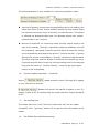
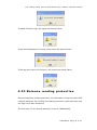
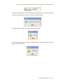
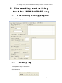
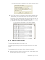
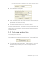
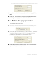
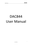
1
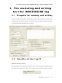
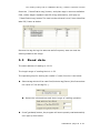
Stronglink SL130 Software Operation Manual UHF RFID Integrated Reader Software operation manual Content | Software operation manual 1 Content 1 CONTENT ....................................................... 2 2 SOFTWARE OPERATION ..................................... 4 2.1 S E T U P T E S T I N G S Y S T E M ........................................................ 4 2.2 E D I T T H E R E A D E R I P I N F O R M A T I O N T E X T .............................. 4 2.3 S T A R T U P T E S T S O F T W A R E ..................................................... 5 2.3.1 S e r i l p o r t c o n n e c t i o n ................................................... 5 2.3.2 N e t w o r k c o n n e c t t i o n ..................................................... 6 2.4 S E T R E A D E R P A R A M E T E R ........................................................ 8 3 THE READERING AND WRITING TEST FOR ISO18000-6B TAG ........................................... 17 3.1 P R O G R A M F O R R E A D I N G A N D W R I T I N G ................................ 17 3.2 I D E N T I F Y A L L T H E T A G I D ................................................... 17 3.3 R E A D D A T A ............................................................................ 18 3.4 W R I T E H E X ........................................................................... 19 3.5 W R I T E P R O T E C T I O N .............................................................. 20 4 THE READING AND WRITING TEST FOR EPC CLASS1G2 TAG ............................................................. 22 4.1 T H E P R O G R A M F O R R E A D I N G A N D W R I T I N G ......................... 22 4.2 D E T E C T T A G E X I S T ............................................................... 24 4.3 G E T T H E E P C N U M B E R W I T H O U T C O N D I T I O N ...................... 24 4.4 G E T E P C N U M B E R A C C O R D I N G T O T H E E P C D A T A ............. 25 4.5 G E T E P C N U M B E R A C C O R D I N G T O T H E T I D D A T A .............. 26 4.6 G E T T H E E P C N U M B E R A C C O R D I N G T O T H E U S E R D A T A ...... 27 4.7 G E T E P C B A N K D A T A O F T H E S P E C I F I E D T A G ..................... 28 4.8 R E A D T H E T I D B A N K D A T A O F S P E C I F I E D T A G ................... 30 4.9 G E T T H E U S E R B A N K D A T A F R O M S P E C I F I E D T A G .............. 30 4.10 G E T P A S S W O R D B A N K D A T A F R O M T H E S P E C I F I E D T A G ... 31 4.11 W R I T E D A T A T O E P C B A N K O F T A G ..................................... 32 4.12 W R I T E R D A T A I N T O U S E R B A N K O F S P E C I F I E D T A G .......... 33 4.13 M O D I F Y T H E P A S S W O R D O F T A G ....................................... 34 4.14 THE WRITE PROTECTION FUNCTION FOR EPC BANK-TID B A N K - U S E R B A N K O F G 2 T A G ......................................................... 35 4.15 THE WRITE PROTECTION FUNCTION FOR PASSWORD BANK OF G 2 T A G ……………………………………………………………………………………………………………..36 4.16 W R I T E P R O T E C T I O N F O R E P C B A N K .................................... 37 4.17 W R I T E P R O T E C T I O N F O R U S E R B A N K .................................. 38 4.18 T H E D A T A B L O C K F O R U S E R B A N K ...................................... 39 090909RevA |Page 2 of 52 Content | Software operation manual 4.19 T H E R E A D - W R I T E P R O T E C T F O R P A S S W O R D B A N K ........... 40 4.20 K I L L T A G ............................................................................... 42 4.21 A L A R M .................................................................................... 43 4.22 S E T R E A D I N G P R O T E C T I O N ................................................... 45 4.23 R E L E A S E R E A D I N G P R O T E C T I O N ........................................... 46 5 THE READING AND WRITING TEST FOR ISO18000-6D TAG ............................................................. 48 5.1 T H E R E A D I N G W R I T I N G P R O G R A M ........................................ 48 5.2 I D E N T I F Y T A G ....................................................................... 48 5.3 R E A D A N D W R I T E D A T A ......................................................... 49 5.4 W R I T E C H A R A C T E R ................................................................ 50 5.5 S E T P A G E P R O T E C T I O N ......................................................... 51 5.6 D E T E C T T H E P A G E P R O T E C T I O N ........................................... 52 090909RevA |Page 3 of 52 Software operation| software operation manual 2 Software Operation 2.1 Set up testing system Connect the equipment as illustrated below, structure a simple reader testing system in the studio: (1) Connect the reader module to PC through the RS232 port or RJ45 port. (2) Run the Demo software of the reader on PC, set reader index and test reading, writing for the reader according to the notes below. 2.2 Edit the reader IP information text Double-click『IPAddress.ini』, open the file, see below, input all IP information which need to connect to this file, then store and close the file. 090909RevA |Page 4 of 52 Software operation | software operation manual 2.3 Start up test software The CD-ROM for contains『application software』Reader1000. exe, this program needs to be in the running in under the environment of Microsoft Windows 95 or higher version of the operating system IBM pc-compatible computers. Run Reader1000. exe can start this software. 2.3.1 Seril port connection PC can implement data exchange with reader through a serial port (RS232). 090909RevA |Page 5 of 52 Software operation | software operation manual Users get a new reader; usually have to do initialized Settings through a serial port, such as IP address, so that we can use network communication. 1. Select the output port, see below. 2. Select the serial port for reader and PC. 3. Click『ConnectReader』button, if connected success, Popup the following clew box. 4. If no reader connected to PC through this serial port, or the selected serial port is wrong, the connection will fail, Popup the following clew box. 2.3.2 Network connection PC can implement data exchange with reader through(TCP/IP). 1. Select the network connection mode, see below. 090909RevA |Page 6 of 52 Software operation | software operation manual 2. Select the reader IP address from the below clew box. 3. Or diredtly input the IPAddress of Reader and Port of Reader to the below clew box. 4. Click『ConnectReader』button, if connect success, popup the below clew box. 5. If no reader connected to PC through RJ45 port, or the the inputted IP information is wrong, the connection will fail, Popup the following clew box. 090909RevA |Page 7 of 52 Software operation | software operation manual 2.4 Set reader parameter Below is the operation page for setting parameter for -『set parameter』: (1) Select Operation Mode There three operating mode for as below: Command: work in this mode, reader only implement after receive legal 090909RevA |Page 8 of 52 Software operation | software operation manual control command through RS232 or RS485, and return thecommand results through the same port. Remarks: Every time run the Demo program and connect the reader success, it will be transferred to command mode automaticly. Timing: output read results reader setout signal automatic every once in a while, read label numbers, if read successful (or legal tags - need validation), then output read results from setting port (Wiegand and RS485 or RS232). If read fail or read illegal tag (need validation), then there is no output. Trigger: work in this mode, reader detects signal change on FIN1 pins automaticly, when detect low electricity at ordinary times; reader starts to send a signal, read label numbers. When FIN1 pins back to high level, stop reading card. The readed card number output from the setted data port. If read invalid card, then output 0xffffffff. (2) Basic Parameters No matter in which operation mode, the below four parameters have to set. Baud Rate of RS232/485 Port: set communication rateof RS232 and RS485 port, can select from 9600, 19200, 38400, 57600, 115200bps. Max Tags of once Reading: Set the most number of labelto read at one time. This parameter should be determined according to the specific requirements. For how labels in antenna radiation within the scope of application at the same time, setting should be larger. But set lower 090909RevA |Page 9 of 52 Software operation | software operation manual values can improve the speed of reading card. RF Power Output: set the output power for the reader. The param has been set to the optimal value; mean has the optimal reading distance and effect. If no special request, please don’t modify this param. Min. Frequency of Carrie): set the min operaton frequency for the reader. Max. Frequency of Carrier: set the max operaton frequency for the reader. For different countries or regions, because local radio rules requirement, have corresponding choice scope of listed the working frequency. Users can choose sensitive frequencies according to local conditions. if just choose a Frequency point, set the Min. Been Carrier and Max to the same; If need to use Frequency hopping, can choose the Min. W.t. fmin Carrier for been, Max. The Carrier for fmax been w.t., as long as fmax > fmin. As below: Setting buzzer: close buzzer, the buzzer don’t sound when identified tag, only show tag information on the interface, open the buzzer, the buzzer sound when identified tag, and show tag information on the interface. (3) Set network parameter The network param has t o be set before connect the reader and PC through TCP/IP. 090909RevA |Page 10 of 52 Software operation | software operation manual (4) Set RS485 network Can make networking through RS485. It has to set an address for each reader before make networking, and enable the reader can connect with PC through TCP/IP. Address range: 0 to 255. Remarks: 0 and 255 are broadcast address,all reader will return application information after receive command with broadcast address. Set networking function: make it can set networking, the reader only execute the command which has address; make it has no networking function, the reader only execute the command which has no address. RS485 network address(1~254): The reader address will set. Relay control. Select relay1 or relay2 or select both, click『relay control』means close relay,popup the clew box for set successful. Don’t select relay1 or relay2, means the relay opened. Parameters for Timing and Trigger Mode The param in the below picture are effected for triger and timing operating mode: 090909RevA |Page 11 of 52 Software operation | software operation manual Read from which Antenna: only use the middle one. If choose the timing or trigger mode, it has to select in advance according actual situation. What will be read from tag: General select the ID No. of the tag as labels No. But for the entrance application, sometimes users need to define their own tags Numbers, and requires to read the writing Numbers as labels Numbers. So should select due to actual situation: EPC C1G2 ID of the Tag SN Written User by ISO18000-6B TK900 EPC ID ID TID The data from 220~223 of user no Port and Format for Output: the tag No. readed automaticly can output from RS232、RS485、wiegand. If output from Wiegand, it also has to set output from wiegand26 or Wiegand34 format. The relationship among utput port、output tag ID bits and and tag species. EPC C1G2 ISO18000-6B TK900 RS232/485/RJ45 All EPC bits The operating param 『 initial address of output card 』 determin output 32bits of 64 bits ID Total 64bits ID wiegand 26 The operating param 『 initial address of output card 』 determin output 32bits of 64 bits ID The operating param 『 initial address of output card 』 determin output 24bits of 64 bits ID The operating param 『 initial address of output card 』 determin output 24bits of 64 bits ID 090909RevA |Page 12 of 52 Software operation | software operation manual EPC C1G2 wiegand34 The operating param 『 initial address of output card 』 determin output 32bits of 64 bits ID ISO18000-6B The operating param 『 initial address of output card 』 determin output 32bits of 64 bits ID TK900 The operating param 『 initial address of output card 』 determin output 32bits of 64 bits ID Wiegand Port Format: there are three kind of Pulse Width and Pulse Interval can be selected for users(as below),usually default to Pulse Width be 28,Pulse Interva be 5. Pulse Width Pulse Interval Pulse Width of Wiegand port Pulse Interval of Wiegand port 40 200 400us 2ms 10 160 100us 1.6ms 5 100 50us 1ms Start Address of ID (0-4): it is for tag ID, the ID of tag has 8Bytes, address0-7. The relationhip among initial address of output tag No、tag species and the data of tag No.(the output port:Weigand26) The initial address range of output tag No. EPC C1G2 (112233445566778899001122) ISO18000-6B (E0044BDF23010000) TK900 (0580C6B1574226A2) 0 223344 044BDF 80C6B1 1 334455 4BDF23 C6B157 2 445566 DF2301 B15742 3 556677 230100 574226 4 667788 010000 4226A2 5 778899 Not be usable Not be usable 6 889900 Not be usable Not be usable 7 990011 Not be usable Not be usable 8 001122 Not be usable Not be usable 090909RevA |Page 13 of 52 Software operation | software operation manual The relationhip among initial address of output tag No、tag species and the data of tag No.(output port: Weigand34) The initial address range of output tag No. EPC C1G2 (112233445566778899001122) ISO18000-6B (E0044BDF23010000) TK900 (0580C6B1574226A2) 0 11223344 E0044BDF 0580C6B1 1 22334455 044BDF23 80C6B157 2 33445566 4BDF2301 C6B15742 3 44556677 DF230100 B1574226 4 55667788 23010000 574226A2 5 66778899 Not be usable Not be usable 6 77889900 Not be usable Not be usable 7 88990011 Not be usable Not be usable 8 99001122 Not be usable Not be usable The relationship among initial address of output tag No、tag species and the data of tag No.(output port: RS232/485) The initial address range of output tag No. EPC C1G2 (112233445566778899001122) ISO18000-6B (E0044BDF23010000) TK900 (0580C6B1574226A2) 0 112233445566778899001122 E0044BDF 0580C6B1574226A2 1 112233445566778899001122 044BDF23 0580C6B1574226A2 2 112233445566778899001122 4BDF2301 0580C6B1574226A2 3 112233445566778899001122 DF230100 0580C6B1574226A2 4 112233445566778899001122 23010000 0580C6B1574226A2 5 112233445566778899001122 Not be usable Not be usable 6 112233445566778899001122 Not be usable Not be usable 7 112233445566778899001122 Not be usable Not be usable 8 112233445566778899001122 Not be usable Not be usable (5) Parameter only for continuing Mode 090909RevA |Page 14 of 52 Software operation | software operation manual The below parameter is only suitable for continuing operation mode: Interval of Reading: means how long pause after each time reading, can select from 30ms,50ms,100ms. Usually identify the slow motion object, the interval time can be long, conversely, it should be short. This param is effected not Wiegand output port. For Wiegand output port, output interval fixed to be 1 second. Manner of output ID: for continuing mode, directly output result or not each time read tag.『directly』represents output immediately once get ID『standard』represents if get the same ID within a long time, output one time defaultly according to the value of 『output interval』, if get the different ID, output it immediately;『timing』represents if get the same ID within long time, and the ID stay in this area, then output one time; if get the same ID within long time, but the leaving time for the tag was long than the value of 『output interval』, once the tag enter again, output its ID immediately. (6) Use the legality parameter(is optimal) Select reader wouldn’t check if the tag ID is legality or not, output to PC directly. Reader will check if the tag ID is legality or not; if it legality, output to PC, if unauthorized, the reader wouldn’t output the tag ID to PC. (7) Set reading time The reader has clock, click『set time』button can set time for reader throughPC. Click 『get time』button, PC can get the time information on the reader. (8) Set TK900 Tag specified parameter. 090909RevA |Page 15 of 52 Software operation | software operation manual The identify progress for TK900 tag, inquires the signal (sending constant RF signal), during the inquiry signal period, tag response ID randomly. Inquires the signal lasting time too short, certain tags may not response; Continuous time is too long, reading speed ill be slow. Perminently reading time: the perminently time presents inquiry signal have 5ms、10ms、20ms、30ms、40ms、50ms、160ms, it is optimal. The number of reading card: represents the number of reader sending information after receive a command from PC. Default Parameter: Reader has certain parameters Settings in factory, if the user has modified some param in use process, and then want to recover to the factory setted parameters, then click the『default parameters』button, you can resume originally set of parameters. (9) Update Parameter Once the parameter selected, click『update parameters』button to write the param to reader’s memory. After success, restart the reader and PC program, the reader will reset param. 090909RevA |Page 16 of 52 The reading-writing test for ISO18000-6B tag | software operation manual 3 The readering and writing test for ISO18000-6B tag 3.1 Program for reading and writing If have to test functionality and performance of the reader, it can be made according to the following way operation. First introduce the operatin way for ISO18000-6B standard tag as below: 3.2 Identify all the tag ID Operation steps as below: Set antenna: can connect an antenna, may use the several antenans, may use just one among them. User can choose it according to actual condition. 090909RevA |Page 17 of 52 The reading-writing test for ISO18000-6B tag | software operation manual Press the 『identification tag』button, and place tags in antenna radiation field, reader began repeated read ID of tag automaticly, until pop-up 『identification tag』button.The card number showed in the『show identified label ID』frame as below: Remove the tag during the antenna radia frequency area can test the reading distance and range. 3.3 Read data The start address of reading is 0-223. The length range of reading block is 1-32. The operating step for testing the reader’s『read』function is as below: Select a tag which will be read from『select a tag』frame (this frame show the result of『list all tag ID』). Select the initial address and block length of reading operaton. Press『get data』button, the program will start repeatly read automaticly until pop-up this button. 090909RevA |Page 18 of 52 The reading-writing test for ISO18000-6B tag | software operation manual The reading result showed at the『informaiton frame』. Each line displayed the result of one reading operation, display with Hex firstly. 3.4 Write HEX The initial address range of writing operation is 8-223. The block length of writing operation is 1-16. The operating step of test reader’s『write』function: Select a tag which will write data from『written data』. Input the initial address of writing operation. Press『write data』button, the program will start repeat write data automaticly until pop-up the button. Write success or not showed in the『informaiton frame』, see below. 『write success! 』represents this operation success. 『write fail!』represents this operation failed, the reason may be distance is too long 、this bank write protection or has been damaged. 090909RevA |Page 19 of 52 The reading-writing test for ISO18000-6B tag | software operation manual Remarks: if the written data more than 4tytes,『writen fail!』may due to patial bytes written failed. The condition for indentifing the tag: users can select the suitalble tag ,then click 『identify tag with condition』button, the tags meet the conditions will be read and show in "show was identification tag ID" column, not content will not be read. 3.5 Write protection The operation step is as below: Select a tag which will plan to protection from『select a tag』. Add the address of the tag in 『write protection』frame. The address range is 8-223. 090909RevA |Page 20 of 52 The reading-writing test for ISO18000-6B tag | software operation manual Press『set protection』button, popup dialog, see as below: Press 『yes』, program will continue protect this tag. If failed, will popup the below dialogue frame: Press 『yes』,try again, protection success, will pop up the below dialog frame: Detect the specified bank of the tag been protected or not (detect address range is 0-223). Press『detec the protection situation』button, pop up the below frame show that this specifed bank has been protected. 090909RevA |Page 21 of 52 The reading-writing test for EPCClass1G2 tag | software operation manual 4 The reading and writing test for EPC Class1G2 tag 4.1 The program for reading and writing (1) The storage unit of EPCC1G2 tag. Devided into four banks: A. EPC: area for storage EPC code, it can store 96Bits EPC code at most. Read write. B. TID: area for storage the ID number setted by the factory, have two 090909RevA |Page 22 of 52 The reading-writing test for EPCClass1G2 tag | software operation manual kind ID number 32 and 64 bits at present. C. Only can be read User: it is differenct in different. The G2 tag from Inpinj has no User area. Philips has 96Bits user area, read write. D. Password: 32Bits access password and 32Bits kill password. Read write. The four bank all can be write proction. Write protection means this bankwill never be writable or can’t write at the unsate situation; read protection means the password bank can’t be read. (2) The reading and writing step for EPCC1G2 tag It is devided into three steps: 1. Selection: select a bank at first, then select a group a tags according to specified data in this bank. 2. Inquiry tag one by one: identify all the tags one by one based on the selection. 3. Access: access an identified tag. Such as read write the four bank, set read write protection and modify password. (3) Set antenna. Select an antenna for test: can select several antenna ports ora single port. (4) Set interval The reading interval can select from:10、20、30、50、100、200 and 500ms,default is 50ms. 090909RevA |Page 23 of 52 The reading-writing test for EPCClass1G2 tag | software operation manual 4.2 Detect tag exist The main function is detect read protect tag. Because in identification tag, read protection tags do not return EPC, only return to full zero data. Press『detect tag』button, the PC send detection command to reader, the reader return the detection result to PC, this process continues 3 seconds later, PC will give detection results. If detected read protected tag, show『have read protected tag within the radio frequency area』. If detected read tag without read protected, show『have tag within the radio frequency area』. If detected no tag, show『no tag within the radio frequency area』. 4.3 Get the EPC No. without condition Operating steps are as below: Firstly, select any bank except the password bank, such as EPC bank, see below: Secondly, set the initial address of data bank to be zero, 0 represents identify all the tag within radio frequency need no condition. See below: 090909RevA |Page 24 of 52 The reading-writing test for EPCClass1G2 tag | software operation manual Thirdly, press『identify tag』button, reader get EPC No. According to last step. The identified EPC No. showed in the top right corner『show identified tag ID』dialogue frame. Figure4.3 4.4 Get EPC No. according to the EPC data According to the specific data segment in EPC bank, choose tags meet the condition, read their EPC number. Operating steps are as below: Firstly, select any bank except the password bank, such as EPC bank, see below: Secondly, set the initial address of data bank, unit with Bit, the start address only should be whole number. Such as the 12. Thirdly, set the length of the data, unit by Bit, such as 3. Fourthly, select data choose HEX for the unit, such as 4, see below. Here the so-called conditions is aimed at a regional data in some tags consecutive patients (bit), who meet the conditions of the tag will be read. The length of the conditional values is not 4Bits integer times, low fill 0. 090909RevA |Page 25 of 52 The reading-writing test for EPCClass1G2 tag | software operation manual Fifthly, press "identification tag" button, reader began to read the label EPC number according to the first four steps setted conditions. Illustrate: see chart 5.1, radiation field have eight tag, if have to meet the conditions: data area initial address is 12, the data length is 3 (namely needs to compare three), selected data is C, the only one card whose ID is 5555555555555555555555 meet, and list to show, see figure 4.3 (because the start bit of card id 12, need to compare the condition of the length is 3, if meet conditional values for hexadecimal 4 or 5 (010 low fill a zero convert 0100 or 0101). Be identified label’s EPC number displayed in the upper-right corner "show identified label ID" dialog box as below: 4.5 Get EPC No. according to the TID data According to the specific data segment in TID bank, choose tags meet the condition, read their EPC number. Operation steps are as below: Firstly, select any bank except the password bank, such asTID bank, see below: Secondly, set the initial address of data bank, unit with Bit, the start address 090909RevA |Page 26 of 52 The reading-writing test for EPCClass1G2 tag | software operation manual only should be whole number. For example: 43. Thirdly, set the length of the data, unit by Bit, such as 4. Fourthly, select data choose HEX for the unit, such as 4, see below. Here the so-called conditions is aimed at a regional data in some tags consecutive patients (bit), who meet the conditions of the tag will be read. The length of the conditional values is not 4Bits integer times, low fill 0. Fifthly, press『identification tag』button, reader began to read the label EPC number according to the first four steps setted conditions. Illustrate: see chart 5.1, radiation field have eight tags, If have to meet the conditions: data area initial address is 43, the data length is 4 (namely needs to compare 4), selected data of D, only card whose ID is 3005FB63AC1F3841EC885555 TID area for E2006004009AE045 meet the condition, and then showed as below: 4.6 Get theEPC No. according to user data According to the specific data segment in TID bank, choose tags meet the condition, read their EPC number. Operation steps are as below: 090909RevA |Page 27 of 52 The reading-writing test for EPCClass1G2 tag | software operation manual Firstly, select any bank except the user bank, such asTID bank, see below: Secondly, set the initial address of data bank, unit with Bit, the start address only should be whole number, such as 7. Thirdly, set the length of the data, unit by Bit, such as 3. Fourthly, select data choose HEX for the unit, such as2, see below. Here the so-called conditions is aimed at a regional data in some tags consecutive patients (bit), who meet the conditions of the tag will be read. The length of the conditional values is not 4Bits integer times, low fill 0. Fifthly, press『identification tag』button, reader began to read the label EPC number according to the first four steps setted conditions. Illustrate: radiation field have several tags, if have to meet the conditions: start address is 7, the data length is 3 (namely needs to compare three), selected data to be 2, and then only for the user ID 053000000000000000000000 data for 32454DAE card meet the condition and listed to show, see figure 5.6 (because the start bit is 7, need to compare the condition of the length is 3, if meet conditional values for hexadecimal 2 (001 low fill a zero convert 0010) . Identified label EPC number displayed in the upper-right corner "show is identified label ID" dialog box as below: 4.7 Get EPC bank data of the 090909RevA |Page 28 of 52 The reading-writing test for EPCClass1G2 tag | software operation manual specified tag EPC bank of EPCC1G2 tag have three parts, order is as follows: CRC-16 is PC value and the redundancy circular check cod of EPC No, CRC are 16Bits, is the FC4BH in the picture. (1) PC comperent from the length of EPC No. and application code.The length of PC value is 16Bits, is the 3000H in picture. (2) EPC is EPC No. Picture 4.6: 0530H (the first character of EPC No.). Can read any EPC block data, operating steps are as below: The first step, select EPC storage area, as below: The second step, select tag, for example『0530000000000000000000』, as below: The third step, select the start address of the data, unit by character, such as 0, as below: The fouth step , set the length of the tag, unit by character, such as 3, as below: The fifth step, press『read data』button, reader began to read the label EPC number according to the first four steps setted conditions. The data displayed in the upper-right corner. 090909RevA |Page 29 of 52 The reading-writing test for EPCClass1G2 tag | software operation manual 4.8 Read the TID bank data of specified tag Can read any TID block data, operating steps are as below: The first step, select TID storage area, as below: The second step, select tag, for example『3005FB63AC1F3841EC880467』, as below: The third step, select the start address of the data, unit by character, such as 0, as below: The fouth step , set the length of the tag, unit by character, such as 3, as below: The fifth step, press『read data』button, reader began to read the labelTID number according to the first four steps setted conditions. The data displayed in the upper-right corner. 4.9 Get the USER bank data from specified tag Can read any USER block data, operating steps are as below: The first step, select USER storage area, as below: 090909RevA |Page 30 of 52 The reading-writing test for EPCClass1G2 tag | software operation manual The second step, select tag, for example『3005FB63AC1F3841EC880467』, as below: The third step, select the start address of the data, unit by character, such as 0, as below: The fouth step , set the length of the tag, unit by character, such as 3, as below: The fifth step, press『read data』button, reader began to read the label USER number according to the first four steps setted conditions. The data displayed in the upper-right corner. 4.10 Get PASSWORD bank data from the specified tag If the password does’t be read protection, it can read any password block data; the password bank has two parts as below: (1) Kill password: 32Bits (2) Access password: 32Bits Operating steps are as below: The first step, select password storage area, as below: 090909RevA |Page 31 of 52 The reading-writing test for EPCClass1G2 tag | software operation manual The second step, select tag, such as 『777777777777777777777777』, see below: The third step, select the start address of the data, unit by character, such as 0, as below: The fouth step set the length of the tag, such as 4, as below: The fifth step, press『read data』button, reader began to read the label USER number according to the first four steps setted conditions. The data displayed in the upper-right corner. AAAAAAAA is kill password, 88888888 is access password. 4.11 Write data to EPC bank of tag Can write16、32、48、64、80 or 96Bits EPC No to the EPC bank at present. CRC-16 and PC value automatic generation according to written EPC. The operation steps are below: The first step, select EPC storage area, as below: The second step, set the EPC No. length, such as 6, means 96Bits, see as below: The third step, if the EPC bank has been set password lock, should fill 090909RevA |Page 32 of 52 The reading-writing test for EPCClass1G2 tag | software operation manual 『Access password』, such as 88888888, see as below: The fourth step, fill EPC No. to 『writen data (Hex.)』, united by HEX,such a『45679464ABCDABCD35467684』. The fifth step, press『write data』button, reader began to write the label EPC data according to the first four steps setted conditions. The written data displayed in the upper-right corner. The sixth step, get EPC No., check if the written right or not. Remark: (1) Only one tag can be there within the radio frequency, otherwise, several tags may all writed the same EPC No. As wrete EPC No. don’t choose a specified tag, so don’t have to choose『select a tag』. (2) All EPC No. are write from address 0, reader pay no attention to『the start address for data area』. (3) When the written data more than 2bytes, show wrong information, may only partial data has been written wrong. 4.12 Writer data into User bank of specified tag The operation steps as below: The first step, select USER storage area, as below: 090909RevA |Page 33 of 52 The reading-writing test for EPCClass1G2 tag | software operation manual The second step, select a tag, such as『45679464ABCDABCD35467684』, see as below: The third step, select the initial address of user bank, such as 0, see as below: The fourth step, set the length of data, such as 4, see as below: The fifty step, if the user bank has been set password, then has to fill the 『Access password』, such as 88888888 see as below: The sixth step, fill data to『written data(Hex.)』, such as 『1234567891234567』. The seventh step, press『written data』button, reader began to write the label USER data according to the first four steps setted conditions. The written data displayed in the upper-right corner. The eighth step, get USER No., check if the written right or not. Remark:When the written data more than 2bytes, show wrong information, may only partial data has been written wrong. 4.13 Modify the PASSWORD of tag The operation steps are as below: The first step, select password storage area, as below: 090909RevA |Page 34 of 52 The reading-writing test for EPCClass1G2 tag | software operation manual The second step, select a tag, such as『45679464ABCDABCD35467684』, see as below: The third step, select the initial address of user bank, such as 0, see as below: The fourth step, set the length of data, such as 2, see as below: The fifty step, fill the『Access password』, such as 88888888, see as below: The sixth step, fill new password to『written data(Hex.)』, such as 『AAAAAAAA』. The seven step, press『write data』button, reader begin to write password according to the condition set be the above sixth step, such as write kill the tag. The written data displayed in the upper-right corner. The eighth step, get new password, check if the written right or not. Remark: When the written data more than 2bytes, show wrong information, may only partial data has been written wrong. 4.14 The write protection function for EPC BANK-TID BANK-USER bank of G2 tag The TID bank of G2 tag has been locked forever by the manufacturer is 090909RevA |Page 35 of 52 The reading-writing test for EPCClass1G2 tag | software operation manual readable only. The EPC bank and USER bank of G2 tag has no protection for reading, the write protection as below: Writable from any state- can write without password, and can set to permanently writable, Writable from the secured state or Never writable in the future. Permanently writable- can write without password, and can’t set to be Writable from the secured state and Never writable; Writable from the secured state- only can write with the password, and can set to permanently writable, Writable from the secured state or Never writable in the future. Never writable-can’t write even with password. 4.15 The write protection function for PASSWORD bank of G2 tag The password of G2 tag can be read and write proteted, the password situation wouldn’t effect use the password. Protection function: Readable and Writable from any state- can read and write without password, and can set to permanently Readable and writable, Readable and Writable from the secured state or Never reader or writable in the future. Permanently readable and writable- can read and write without password, and can’t set to be readable or Writable from the secured state and Never readable or writable; Readable and Writable from the secured state- only can read orwrite with the password, and can set to permanently readable and writable, readable and Writable from the secured state or Never readable or writable in the future. Never readable or writable-can’t read or write even with password. 090909RevA |Page 36 of 52 The reading-writing test for EPCClass1G2 tag | software operation manual Remarks: set read write protect for tag, should know the access password of tag in advance. 4.16 Write protection for EPC bank The first step, select the EPC bank,as below: The second step, select a tag, such as『45679464ABCDABCD35467684』,as below: The third step, select the Writable from the secured state (or Writable from any state, or permanently writable or never writable), as below: The fourth step, fil the l『access password』,the access password for tag 『45679464ABCDABCD35467684』is 88888888, see as below: The fifth step, press『set protecting』button, popup the below dialogue box: The sixth step, press『no』, then the above operation invalid, press 090909RevA |Page 37 of 52 The reading-writing test for EPCClass1G2 tag | software operation manual 『yes』,according to the before four step setted condition, if success, popup the below frame, represents the EPC bank has set to be password lock. The seventh step, write data to EPC bank, check if the set protection suceess or not. 4.17 Write protection for USER bank The first step, select the USER bank, as below: The second step, select a tag, such as『45679464ABCDABCD35467684』, see as below: The third step, select the Writable from the secured state (or Writable from any state, or permanently writable or never writable), as below: The fourth step, fill the l『access password』,the access password for tag 『45679464ABCDABCD35467684』is 88888888, see as below: The fifth step, press『set protecting』button, popup the below dialogue box: 090909RevA |Page 38 of 52 The reading-writing test for EPCClass1G2 tag | software operation manual The sixth step, press『no』, then the above operation invalid, press 『yes』,according to the before four step setted condition, if success, popup the below frame, represents the EPC bank has set to be password lock. The seventh step, write data to USER bank, check if the set protection suceess or not. 4.18 The data block for USER bank Only the SL3-ICS-10 UCODE EPC G2 tags from Philip provide this kind of lock. Each block has 32bits (4bytes or 2 words). Once the block has been locked, it can’t be modified forever. The first step, select a tag, such as『45679464ABCDABCD35467684』, see as below: The second step set the data address, such as 6 or 7, will protect 6 and 7two words as below. The SL3-ICS-10 tag has 14 Words at present,the address is 0~13. The initial addres(character) The data protected (character) 0 or 1 0 and 1 2 or 3 2 and 3 4 or 5 4 and 5 been 090909RevA |Page 39 of 52 The reading-writing test for EPCClass1G2 tag | software operation manual 6 or 7 6 and 7 8 or 9 8 and 9 10 or 11 10 and 11 12 or 13 12 and 13 The third step,fill the access password, the access password of tag 『45679464ABCDABCD35467684』is 88888888, see as below: The fourth step, press『set lock』button, popup the below dialogu box: press『yes』button, the reader will send block lock command to the tag, if success, PC will popup the below frame. Set lock success or not, operate to check it. If fialed, will popup error information accordingly. 4.19 The read-write protect for PASSWORD bank The first step, select the user bank, see below: 090909RevA |Page 40 of 52 The reading-writing test for EPCClass1G2 tag | software operation manual The second step, select the access password (or kill password), see below: The third step, select a tag, such as『45679464ABCDABCD35467684』, see below: The fourth step, select the Readable and Writable from the secured state (or Readable and Writable from any state, or permanently readable and writable or never readable or writable), as below: The fifth step, fill the『access password』, the access password for tag 『45679464ABCDABCD35467684』is 88888888, see below: The sixth step, press『set protection』button, popup the below frame: The seven step, press『no』, then the above operation invalid, press 『yes』,according to the before four step setted condition, if success, popup 090909RevA |Page 41 of 52 The reading-writing test for EPCClass1G2 tag | software operation manual the below frame, represents the USER bank has set to be password lock. The eighth step, write data to USER bank, check if the set protection suceess or not. 4.20 Kill tag Once the tag has been killed, it will never answer the reader. Remarks: this function should be cautious to use. The first step, select a tag『Select a Tag』, such as 『222222222222222222222222』, see below: The second step, fill the kill password to『Password』, HEX. , the kill passwordof tag『222222222222222222222222』is 00000000, see as below; The third step, press『Delete Tag』button, popup the below frame: The foutth step, press『no』, then the above operation invalid, pres 『yes』,according to the before three step setted condition, if success, popup the below frame, represents the tat has been killed. 090909RevA |Page 42 of 52 The reading-writing test for EPCClass1G2 tag | software operation manual The fifth step, read the EPC No. to check if killed the tag successful or not. 4.21 Alarm Only the SL3-ICS-10 UCODE EPC G2 tag of Philips has this function, this function is similar to the bar magnet used in library and supermarket. When the tag on the goods are under the alarm situation, once the reader find the tag will alarm. Set alarm stature The first step, select a tag, such as『45679464ABCDABCD35467684』,see as below: The second step, fill the access password, Hex., the access password of tag 『45679464ABCDABCD35467684』is 88888888, see as below: The third step, select 『alarm』 The fourth step, press『set alarm』button, reader send set alarm command , if success, popup the below frame: 090909RevA |Page 43 of 52 The reading-writing test for EPCClass1G2 tag | software operation manual If failed, popup popbox, the failure reason may be the reader left the radiao frequency or the access password is wrong. Check if set alarm successfully. (1) Set no alarm The first step, select a tag, such as『45679464ABCDABCD35467684』, see as below: The second step, fill the access password, Hex., the access password of tag 『45679464ABCDABCD35467684』is 88888888, see as below: The third step, select 『no alarm』 The fourth step, press『set alarm』button, reader send set alarm command , if success, popup the below frame: If failed, popup popbox, the failure reason may be the reader left the radiao frequency or the access password is wrong. Check if set no alarm successfully. 090909RevA |Page 44 of 52 The reading-writing test for EPCClass1G2 tag | software operation manual (2) Check alarm Press『EasAlarm』button, reader send check alarm command to tag. If found some tags are in the alarm situation, the buzzer will alarm, and there would be red light twinkle on the PC interface. If haven’t foud any tag under the alarm situation, buzzer will not alarm and there would be no tips on the PC. Once found the alarm, shut up the relay 4 seconds, if found alarm again,the relay will delay 4 seconds to shut up. 4.22 Set reading protection Only the Philips SL3-ICS-10 UCODE EPC G2 tag has these two functions, the reading protected tag only return zero data to the identification command from the reader, but not EPC. The first step, select a tag, such as『222222222222222222222222』, see as below: The second step, fill the access password, Hex., the access password of tag 『222222222222222222222222』is 11111111, see as below: The third step, press『set reading protect』button, reader send out set reading protecting command, if success, will pop up the below frame: 090909RevA |Page 45 of 52 The reading-writing test for EPCClass1G2 tag | software operation manual If reader found no tag, will popup the below frame: If the access password is wrong, then popup the below frame: If the tag don’t have this function, will popup the below frame: 4.23 Release reading protection Once the tag been reliefed protection, the information in tag can return EPC nomally. Remarks: For reliefing the reading protection, there should be only one tag in the radio frequency. The first step, fill the access password, such as『AAAAAAAA』 ; 090909RevA |Page 46 of 52 The reading-writing test for EPCClass1G2 tag | software operation manual The second step, press『releif reading protecting』button, reader send relief command to the tag, if success, popup the below frame: If reader found no tag, will popup the below frame: If the access password is wrong or the tag doesn’t have this function, then popup the below frame: 090909RevA |Page 47 of 52 The reading-writing test for ISO18000-6D tag| software operation manual 5 The reading and writing test for ISO18000-6D tag 5.1 The reading writing program To the TK900 tag, operate as below: 5.2 Identify tag The operation step is as below: Select antenna 090909RevA |Page 48 of 52 The reading-writing test for ISO18000-6D tag | software operation manual Lay a tag in the radio frequency area, press『identify tag』button, the reader begin to get the ID of tag reapedly and automatically, until popup this button. The No. showed in the『Showing the identified ID』frame, as below; 『Showing the identified ID』listed all the ID No. Has been identified. Remove the tag within the radio frequency area, can check the reading range. 5.3 Read and write data ISO18000-6D don’t have the user bank, EM4422 and EM4442 have 15 pages user bank, 8bytes per page. The range of data start address: 0-14. The length range of data page: 1-15. The operating step for test reader’s『read』function is as below: Select a tag which is reading to be read from the『select a tag』frame(this frame showed that『list all tag’s ID』 ) Set the start address for reading, such as 0. Set the page for reading, such as10. see as below: 090909RevA |Page 49 of 52 The reading-writing test for ISO18000-6D tag | software operation manual Press『read』button, the program will start reading repeatedly and automatically, until popup this button. The result will show in the 『informaiton』frame, see as below. Each line show one result, as : No. ××Page, the data value of this page is (showed by HEX:××××××× ×), the data value of this page is (showed by ASCII str:××××××× ×). Each operation can display in cycle within 15pages. 5.4 Write character The start data page address for writing is 0-14. The page lengh for writing only can write a page onet time, other value invalid. The operating step for test reader’s『write』function is as below: Select a tag which are ready to be write from the『written data』frame. At most 8 bytes can write on one page. 090909RevA |Page 50 of 52 The reading-writing test for ISO18000-6D tag | software operation manual Fill the address for writing data: Press『write data』button, the program will start to write repeatly and automatically, until popup this button. The operating result showed in the『information』frame. If showed『write date failed』, represents this writing operation failed, the reason may be too long distance, this bank has been reading protected or has been destroyed. 5.5 Set page protection The operating step is as below: Select a tag which are ready to be protected from the 『choose a tag』frame. Fiil the start page of the selected tag in 『data protection』, such as 12. The address range of the tag is 0-14. Fill in the pages should be protected. 090909RevA |Page 51 of 52 The reading-writing test for ISO18000-6D tag | software operation manual Press『set protection』button, popup『protect the twelve page』dialogue frame: Press『yes』, the program will continue to select address to protect. Protecting success popup in the 『information』frame. 5.6 Detect the page protection The operation steps are as below: Select a tag which are ready to be detect from『select a tag』frame Fiil the start page of the selected tag in 『data protection』, such as 12. The address range of the tag is 0-14. Fill in the pages should be protected, the page should be 1, and others are invalid. Press『detect protection situation』butoon, pop up the below frame, represents this page has been protected. 090909RevA |Page 52 of 52