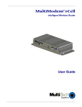
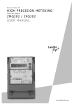
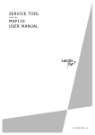
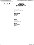
1
Communication
Industrial and Commercial
CU-E20, E22
E65C
User Manual
E65C CU-E20, E22 communication units provide
Ethernet communication between E650 or E850 meters and a central system.
Date: 06.11.2009
Filename: H 71 0200 0316 en - CU-E2x - User Manual.docx
© 2009 Landis+Gyr AG
H 7 1 0200 0316 e en
2/22
Revision History
Revision History
Version
Date
Comments
a
19.10.2004
First edition
b
16.04.2009
New RS485 installation note
c
12.10.2009
Market name change and E21 discontinuation
d
e
06.11.2009
05.01.2010
Revision of entire document (layout, wording)
Document number correction
Copyright © 2009, Landis+Gyr. All rights reserved. Subject to change without notice.
Landis+Gyr AG
Feldstrasse 1
CH-6301 Zug
Switzerland
Phone: +41 41 935 6000
www.landisgyr.com
© Landis+Gyr AG
H 71 0200 0316 e en – E65C – User Manual
About this Document
3/22
About this Document
Range of validity
The present user manual applies to communication units E65C CU-E20
and CU-E22 – designated CU-E2x below.
Purpose
This user manual supplements the operating instructions of the meter and
of the CU-adapter E65C CU-ADP1 and is incomplete without the data
contained therein. Together with these operating instructions, the user
manual contains all the information necessary for the operation of the
CU-E2x communication unit for the intended purpose. This includes:
•
Provision of knowledge concerning characteristics, construction and
function of the communication unit CU-E2x
•
Information about possible dangers, their consequences and measures to prevent any danger
•
Details concerning the performance of all work throughout the service
life of the communication unit CU-E2x (installation, commissioning, operation, maintenance, shutting down and disposal)
Target group
The contents of this user manual are intended for technically qualified personnel of energy supply companies responsible for the system planning,
installation and commissioning, operation, maintenance, decommissioning
and disposal of the meters.
Reference documents
The technical data and the functional description of the communication unit
CU-E2x can be found in the following documents:
•
H 71 0200 0320 en "Technical Data E65C CU-E20, E22"
•
H 71 0200 0321 en "Functional Description E65C CU A, B, M, G, D, P,
E, Q"
•
H 71 0200 0323 en "User Manual E65C CU-ADP1"
H 71 0200 0316 e en - E65C - User Manual
© Landis+Gyr AG
4/22
Table of Contents
Table of Contents
1 Description of Unit ________________________________________________________5 1.1 Scope of Application _____________________________________________________5 1.2 Characteristics _________________________________________________________5 1.3 Type Designation _______________________________________________________5 1.4 Functions _____________________________________________________________6 1.4.1 Ethernet Interface _____________________________________________________6 1.4.2 CS-Interface _________________________________________________________6 1.4.3 RS485-Interface ______________________________________________________6 2 Safety ___________________________________________________________________7 2.1 Safety Information _______________________________________________________7 2.2 Responsibilities _________________________________________________________7 2.3 Safety Regulations ______________________________________________________8 3 Mechanical Construction ___________________________________________________9 3.1 Overview ______________________________________________________________9 3.2 Interface Connections ___________________________________________________10 3.2.1 Connections CU-E20 _________________________________________________10 3.2.2 Connections CU-E22 _________________________________________________11 3.3 Faceplate ____________________________________________________________12 3.4 LEDs ________________________________________________________________12 4 Installation/De-installation _________________________________________________13 4.1 Fitting in Meter ________________________________________________________13 4.2 Fitting in CU-Adapter CU-ADP1 ___________________________________________14 4.3 Connecting the Communication Unit _______________________________________15 4.3.1 Connecting the Ethernet Interface _______________________________________15 4.3.2 Connecting the CS-Interface ____________________________________________15 4.3.3 Connecting the RS485-Interface _________________________________________17 4.3.4 Final Operations _____________________________________________________17 4.4 Commissioning and Functional Check ______________________________________17 4.5 Removal/Exchange of Communication Unit __________________________________17 5 Operation _______________________________________________________________18 6 Service _________________________________________________________________19 6.1 Troubleshooting _______________________________________________________19 6.2 Repairing the Communication Unit _________________________________________19 7 Maintenance ____________________________________________________________20 8 Disposal ________________________________________________________________21 9 Index___________________________________________________________________22 © Landis+Gyr AG
H 71 0200 0316 e en – E65C – User Manual
0BDescription of Unit
5/22
1
Description of Unit
1.1
Scope of Application
The communication unit CU-E2x can be fitted in and removed from the following Landis+Gyr meters without opening the calibration seal:
•
Landis+Gyr E650 ZxD300/400xT industrial and commercial meters
•
Landis+Gyr E850 ZxQ high-precision meters
Inserted in a CU-adapter CU-ADP1, the communication unit CU-E22 can
also be used with other meters (e.g. Landis+Gyr E650 ZxD300/400xR,
ZMD100AR, ZxB or meters from other manufacturers). Connection to the
meter is made in this case via an interface in the communication unit (CS or
RS485).
1.2
Characteristics
The communication unit CU-E2x always contains a built-in Ethernet interface and depending on version an RS485 and a CS interface (CU-E22). It
is used to supplement the meters listed above.
The Ethernet interface serves to read out or re-parameterize the meter from a
central station with a LAN via the Internet.
The RS485 and CS interfaces can be used for the connection of meters separated by greater distances (multiple connections). The CS interface can be parameterized as active or passive interface, so that it can be used as master or
slave as required with multiple connections.
With external application of the communication unit CU-E22 in a CU adapter
one of the existing interfaces of the communication unit is required for connection to the meter.
1.3
Type Designation
The type designation of the communication unit CU-E2x is added to that of
the meter (see meter user manual), but is not shown on the main faceplate
of the meter. It is specified directly on the case of the communication unit
and can be seen through the front door of the meter through an opening on
the tariff faceplate.
The communication unit CU-E2x is available in the following versions:
Type
Ethernet
RS485
CS+
CU-E20
CU-E22
H 71 0200 0316 e en – E65C – User Manual
© Landis+Gyr AG
6/22
1.4
0BDescription of Unit
Functions
A functional description of the communication unit CU-E2x is provided
separately. The following main functions are briefly summarised below.
1.4.1
Ethernet Interface
The Ethernet interface is standardised to IEEE 802.3. This is a standard for
data transmission in packet form in LAN networks (Local Area Network).
The Ethernet interface permits connection to the LAN by means of the
transmission control protocol TCP/IP (Transmission Control Protocol/Internet Protocol). The maximum transmission speed is 10 Mbps.
1.4.2
CS-Interface
The serial bi-directional CS-interface is standardised to IEC 62056-21 or
DIN 66258. It supports both the communication protocol to IEC 62056-21
as well as communication according to dlms and can be operated both
actively and passively.
1.4.3
RS485-Interface
The serial bi-directional RS485-interface is standardised to ISO-8482. It is
basically intended for the connection of several meters (up to 31) via a
master to a communication path and therefore to read out the meter data or
to perform service functions (such as setting of start values, time/date, etc.).
© Landis+Gyr AG
H 71 0200 0316 e en – E65C – User Manual
1BSafety
7/22
2
Safety
2.1
Safety Information
In this manual, attention is drawn to dangers with symbols, reflecting the
danger level, i.e. the severity and probability of any danger, as follows:
Definition of Danger
For a possibly dangerous situation, which could result in severe physical
injury or fatality.
Definition of Warning
For a possibly dangerous situation, which could result in minor physical
injury or material damage.
L
Definition of Note
For general details and other useful information to simplify the work.
In addition to the danger level, safety information also describes the type
and source of the danger, its possible consequences and measures to
counteract the danger.
2.2
Responsibilities
The owner of the communication units is responsible that all persons
engaged on work with the communication units:
•
Are competent and qualified in accordance with national regulations
(see ISSA "Guideline for Assessing the Competence of Electrically
Skilled Persons").
•
Have read and understood the relevant sections of the user manual.
•
Strictly observe the safety regulations (according to the following section) and the instructions in the individual chapters.
The owner of the communication units is also responsible for:
•
The protection of persons.
•
The prevention of material damage.
•
The training of personnel.
Landis+Gyr AG provides training courses for this purpose on specific
equipment; please contact the relevant agent if interested.
H 71 0200 0316 e en – E65C – User Manual
© Landis+Gyr AG
8/22
2.3
1BSafety
Safety Regulations
The following safety regulations must be observed at all times:
•
Changing of the communication unit must only be made on meters not
under voltage.
•
Devices which have fallen down should not be installed, even if no
damage is apparent, and should be returned for testing to an authorised service centre (internal damage possible).
•
Communication units must never be cleaned with running water or
high pressure devices. Water can cause short-circuits or damage el.
components.
Note also the safety instructions given in the user handbooks for the meter
and the CU-adapter CU-ADP1 as far as they are relevant to the communication units.
© Landis+Gyr AG
H 71 0200 0316 e en – E65C – User Manual
2BMechanical Construction
9/22
3
Mechanical Construction
3.1
Overview
The communication unit CU-E2x is a unit complete in itself with its own
plastic case.
1
1
2
3
4
Fig. 3.1
1
2
3
4
Communication unit CU-E2x, removed
10-pin connector
Faceplate
Transparent strip through which the LEDs are visible
Interface connections
The faceplate of the communication unit fitted in the meter is visible with
the meter front door open. When fitted in a CU-adapter, the faceplate can
be seen through the transparent front cover.
The interface connections are situated underneath, while a 10-pin connecting plug provides connection at the rear with the meter electronics or CUadapter.
Five LEDs on the circuit card optically indicate through the transparent strip
under the face plate transmission and reception activities.
The communication unit has no seal of its own. It is secured when built-in
by a utility seal of the meter or CU-adapter.
H 71 0200 0316 e en – E65C – User Manual
© Landis+Gyr AG
10/22
3.2
2BMechanical Construction
Interface Connections
The Ethernet connection of the communication unit CU-E2x is made via an
RJ45 socket with the following pin assignment:
Pin No.
Terminal
Signal
1
TxD+
Transmitted Data +
2
TxD-
Transmitted Data -
3
RxD+
Received Data +
6
RxD-
Received Data -
The pins of the RJ45 socket are numbered as follows:
8
1
Fig. 3.2
Pin numbering of RJ45 socket
The pins of the RJ12 socket are numbered as follows:
6
1
Fig. 3.3
3.2.1
Pin numbering of RJ12 socket
Connections CU-E20
1
Fig. 3.4
1
© Landis+Gyr AG
Connections CU-E20
Ethernet interface (RJ45 socket)
H 71 0200 0316 e en – E65C – User Manual
2BMechanical Construction
11/22
DC
DC
+
Ethernet
RxD+ TxD+
TxD8 7 6 5 4 3 2 1
RxD-
Fig. 3.5
3.2.2
Connection diagram communication unit CU-E20
Connections CU-E22
1
Fig. 3.6
1
2
3
2
3
Connections CU-E22
RS485 interface (RJ12 socket)
CS interface (screwless spring-type terminals WAGO)
Ethernet interface (RJ45 socket)
With the screwless spring-loaded terminals of the CS interface the
polarities are determined as follows:
+ left terminal (23)
– right terminal (24)
The RJ12 socket of the RS485-interface has the following pin assignment:
Pin No.
Terminal
Signal
1
c
Signal Ground
2
a
Data a
3
b
Data b
4
b
Data b
5
a
Data a
6
c
Signal Ground
H 71 0200 0316 e en – E65C – User Manual
© Landis+Gyr AG
12/22
2BMechanical Construction
DC
DC
+
Ethernet
CS
+
-
RxD+ TxD+
TxD8 7 6 5 4 3 2 1 6
RS485
b
RxD-
5
4
3
a
2
c
1
23 24
Fig. 3.7
3.3
Connection diagram communication unit CU-E22
Faceplate
The faceplate of the communication unit CU-E2x has the following appearance depending on version:
99 999 003-2
2004
1
2
3
8
4
7
CU-E22
5
TX
6
Fig. 3.8
1
2
3
4
5
6
7
8
RX
CON
LAN
LNK
Faceplate of the communication unit CU-E2x (example CU-E22)
Serial number
Year of construction
dlms symbol depending on parameterization
Diagram
Ownership designation and bar code
Designation of transmit/receive LEDs
Type designation
Insulation class and CE sign
The faceplate may contain other country-specific data, e.g. warnings, etc.
3.4
LEDs
The five LEDs TX, RX, CON, LAN and LNK designated on the face plate
are fitted on the circuit cards and can be seen through the transparent strip
below the face plate. Their function is described in chapter 5 "Operation".
© Landis+Gyr AG
H 71 0200 0316 e en – E65C – User Manual
3BInstallation/De-installation
13/22
4
Installation/De-installation
4.1
Fitting in Meter
No voltage to meter when fitting
In order to avoid hazardous electric shocks, ensure there is no voltage
applied to the meter when fitting the communication unit. Contact with live
parts is dangerous to life. Disconnect the meter from the power supply as
described in the meter user manual.
Fit the communication unit in the meter as follows:
1.
Ensure that no voltage is applied to the meter.
2.
Remove the utility seals on the front door and terminal cover.
3.
Open the front door and remove the terminal cover.
Fig. 4.1
Preparing the meter for fitting the communication unit
4.
Remove the built-in "dummy" communication unit.
5.
Insert the communication unit carefully at the place provided in the
meter. Ensure correct fitting of the connector.
H 71 0200 0316 e en – E65C – User Manual
© Landis+Gyr AG
14/22
3BInstallation/De-installation
Fig. 4.2
6.
4.2
Fitting communication unit in meter
Close and seal the front door.
Fitting in CU-Adapter CU-ADP1
No voltage to CU-adapter when inserting communication unit
There must be no voltage applied to the CU-adapter when the communication unit is inserted. Contact with live parts is dangerous to life. If necessary, disconnect the CU-adapter from the power supply as described in the
CU-ADP user manual.
Fit the communication unit CU-E22 in the CU-adapter CU-ADP1 as follows:
1.
Remove the utility seals on the front cover and on the terminal cover.
2.
Remove the front cover and the terminal cover.
Fig. 4.3
© Landis+Gyr AG
Preparing the CU-adapter CU-ADP1 for fitting the communication unit
H 71 0200 0316 e en – E65C – User Manual
3BInstallation/De-installation
15/22
3.
Insert the communication unit carefully at the position provided in the
CU-adapter by first moving this forwards under the cam and then
pressing down at the rear. Ensure the correct fit of the plug. The front
cover should only be replaced after connecting.
2
1
Fig. 4.4
4.
Fitting communication unit in CU-adapter CU-ADP1
Connect the communication unit to the meter (via RS485 or CS interface) and the adapter to mains and mount the front cover, see User
Manual of the adapter: H 71 0200 0323 en.
4.3
Connecting the Communication Unit
4.3.1
Connecting the Ethernet Interface
Insert the connecting cable with the RJ45 connector in the right socket
labelled Ethernet until the connector can be heard to engage. Connect the
other end of the cable to the LAN.
4.3.2
Connecting the CS-Interface
Connect the CS-interface of communication unit CU-E22 according to the
connection diagram as follows:
1.
Shorten the connecting wires to the required length and strip them for
approx. 4 mm (wires and strands up to 2.5 mm2 can be connected).
2.
If stranded wire is used as phase connection line, it has to be provided
with ferrules for connection.
3.
Connect the connecting wires to the screwless spring-loaded terminals
(the terminals are numbered as shown on the connection diagram):
- Insert a size 1 screwdriver in the upper opening and insert it turning
slightly upwards (Fig. 4.5 A).
- Now place the stripped connecting wire in the lower opening and
hold it there securely (Fig. 4.5 B).
- Withdraw the screwdriver. The connecting wire is then firmly fixed
(Fig. 4.5 C).
H 71 0200 0316 e en – E65C – User Manual
© Landis+Gyr AG
16/22
3BInstallation/De-installation
ca
A
B
Fig. 4.5
.4
mm
C
Connection in screwless spring-loaded terminals
Bare end of connecting wire must not be too long
The insulation of the connecting wire must extend as far as the terminal
indentation, i.e. there must be no further bare part of the connecting wire
visible above the terminal edge (as shown in Fig. 4.5 C). Touching live
parts is dangerous to life. The stripped part of the connecting wire should
be shortened if necessary.
Only one wire or ferrule per terminal
Only one wire or ferrule with strand(s) may be connected in screwless
spring-loaded terminals. The terminal could be damaged or the contact
could not properly made.
If a connecting wire must be disconnected again for any reason, this is
performed in the reverse sequence:
A
Fig. 4.6
L
© Landis+Gyr AG
B
C
Releasing connection from spring-loaded terminal
Damage to terminals
Never withdraw connecting wires with the terminal closed, since this could
damage the terminal.
H 71 0200 0316 e en – E65C – User Manual
3BInstallation/De-installation
4.3.3
17/22
Connecting the RS485-Interface
Insert the connecting cable with the RJ12 connector in the right socket
labelled RS485 until the connector engages. Connect the other end of the
cable to the nearest unit of the RS485 multiple connection.
If its RS485-interface is provided with two internally looped RJ12 sockets
(e.g. CU-B2), the other end of the cable can also be provided with an RJ12
plug. If, however, only one RJ12 socket is present on the nearest unit (e.g.
CU-E22) the loop for the RS485-interface must be formed with a T-piece
outside the unit.
B2
RS485
E22
RS485
RS485
External wiring of RS485
In order to function correctly, all 3 wires (data a, data b and Common GND)
must be connected. RS485 operation with only 2 wires (without Common
GND) is forbidden as the RS485 interface may not function correctly or be
damaged.
4.3.4
Final Operations
If the communication unit is fitted in a meter, replace the terminal cover and
seal with a utility seal.
If the communication unit is fitted in a CU adapter, replace the front cover
and terminal cover and seal both with utility seals.
4.4
Commissioning and Functional Check
After switching on the mains voltage, LEDs TX and RX flicker briefly. The
communication unit CU-E2x is then ready for operation.
When the Ethernet connection is made, the LED LNK lights. A remote readout of the meter data via the LAN should be performed as a functional check.
If a multiple connection to further appliances is present, check their function.
4.5
Removal/Exchange of Communication Unit
The communication unit is exchanged or removed from the meter in
reverse order of the installation (see sections 4.1 and 4.2).
H 71 0200 0316 e en – E65C – User Manual
© Landis+Gyr AG
18/22
5
4BOperation
Operation
The communication unit CU-E2x has no control elements. To display
communication processes it has five LEDs, which are visible through
the transparent strip below the faceplate.
LEDs
© Landis+Gyr AG
Functions of the five LEDs during normal operation:
•
CON: This green LED is continuously lit if there is a connection
between the communication unit and the central station. Data
exchange can take place.
•
RX: This yellow LED indicates the reception of characters via the
Ethernet or the RS485 interface. If this LED is flashing, it indicates
reception of the "Ring" function.
•
TX: This yellow LED indicates the transmission of characters via the
Ethernet or the RS485 interface.
•
LAN: This yellow LED lights when transmitting or receiving frames
and on detection of data collisions.
•
LNK: This green LED lights while valid link pulses are detected, i.e.
when the Ethernet connection is made. The LED is off outside the time
window parameterized. It flashes until connection is made.
H 71 0200 0316 e en – E65C – User Manual
5BService
19/22
6
Service
6.1
Troubleshooting
The following points should first be checked with functional disturbances in
the modem connection or the interfaces:
1.
Is the mains voltage present (meter liquid crystal display legible, green
LED on CU-adapter lights)?
2.
Is the maximum permissible ambient temperature not exceeded?
3.
Are there any changes or damage visible in the installation?
If none of the points listed is the cause of the fault, the communication unit
should removed and sent to the responsible service and repair centre.
6.2
Repairing the Communication Unit
Communication units must only be repaired by an authorised service and
repair centre (or by the manufacturer).
Meter operation only with communication unit or "dummy"
For safety reasons the meter must not be operated without communication
unit or a "dummy" communication unit.
Adopt the following procedure if a repair is necessary to the communication
unit:
1.
If installed, remove the communication unit and fit a replacement communication unit. If no spare communication unit is available, a "dummy"
unit must be used.
2.
Describe the error found as exactly as possible and state the name
and telephone number of the person responsible in case of inquiries.
3.
Pack the communication unit to ensure it can suffer no further damage
during transport. Preferably use the original packing if available. Do not
enclose any loose components.
4.
Send the communication unit to the responsible service and repair
centre.
H 71 0200 0316 e en – E65C – User Manual
© Landis+Gyr AG
20/22
7
6BMaintenance
Maintenance
The communication unit CU-E2x requires no maintenance.
Never use running water for cleaning
The communication units must not be cleaned with running water or with
high pressure devices. Water penetrating can cause short-circuits or damage electronic components.
© Landis+Gyr AG
H 71 0200 0316 e en – E65C – User Manual
7BDisposal
8
21/22
Disposal
Based on the data specified in environmental certificate ISO 14001, the
components used in the communication units are largely separable and can
therefore be taken to the relevant disposal or recycling point.
L
Observing local regulations
Observe the local disposal and environmental protection regulations for the
disposal of the communication units.
Components
Printed circuit
boards
Disposal
Electronic waste: disposal according to local regulations.
Metal parts
Sorted and taken to collective materials disposal point.
Plastic
components
Sorted and taken to recycling (regranulation) plant or if
no other possibility to refuse incineration.
H 71 0200 0316 e en – E65C – User Manual
© Landis+Gyr AG
22/22
9
8BIndex
Index
About this document ....................................... 3
Characteristics ................................................ 5
Commissioning ............................................. 17
Connecting
CS interface .............................................. 15
Ethernet interface ...................................... 15
RS485 interface ........................................ 17
Connection diagram
CU-E20 ..................................................... 11
CU-E22 ..................................................... 12
Connections .................................................. 10
CU-E20 ..................................................... 10
CU-E22 ..................................................... 11
CS interface .................................................... 6
CU adapter CU-ADP1 .................................. 14
De-installation ............................................... 13
Description of unit ........................................... 5
Disposal ........................................................ 21
Electronic waste ........................................... 21
Ethernet interface ........................................... 6
Faceplate ...................................................... 12
Fitting
in CU adapter ............................................ 14
in meter ..................................................... 13
Functional check ........................................... 17
Functions of LEDs ........................................ 18
© Landis+Gyr AG
Installation .................................................... 13
Interface connections ................................... 10
LED ............................................................... 18
LEDs ............................................................. 12
Maintenance ................................................. 20
Mechanical construction ................................. 9
Operation ...................................................... 18
Pin numbering of RJ12 socket ...................... 10
Pin numbering of RJ45 socket ...................... 10
Qualifications .................................................. 7
Releasing connection from spring-loaded
terminal...................................................... 16
Removal of communication unit.................... 17
Repairing the communication unit ................ 19
Responsibilities ............................................... 7
RJ12 socket pin numbering .......................... 10
RJ45 socket pin numbering .......................... 10
RS485 interface .............................................. 6
Safety ............................................................. 7
Scope of application ....................................... 5
Seals ............................................................... 9
Service .......................................................... 19
Training ........................................................... 7
Troubleshooting ............................................ 19
Type designation ............................................ 5
Versions .......................................................... 5
H 71 0200 0316 e en – E65C – User Manual