1
4.
For the Service Technician
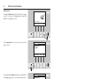
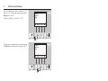
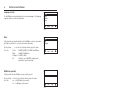
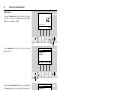
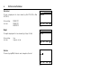
Select the required item, „Values“, „Parameters“, „Actuator test“ or „Settings“ and confirm by pressing the
Choose button – Fig. 76.
For further settings, see sections 4.7.1 - 4.7.4.
Values
Parameters
Actuator test
Settings
Choose
Back
Fig. 76
Values
Parameters
Actuator test
Settings
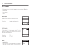
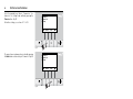
The menu item or sub-menu item is exited by pressing
the Back button or after a delay of 10 minutes – Fig. 77
Choose
Back
Fig. 77
4.7.1
Values
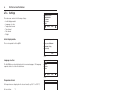
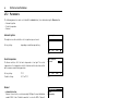
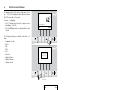
The following values are displayed:
Temp. Boiler
Temp. chamb.
Fan-speed
Pos. Prim. airfl.
Pos. Sec. airfl.
O2 signal
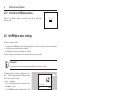
Temp. Boiler
The current boiler temperature is displayed in °C.
Temp. chamb.
The current temperature in the combustion chamber is displayed in °C.
Fan-speed
68°C
578°C
2500 rpm
60%
30%
18,1%
Back
Fig. 78
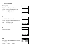
The nominal speed of the blower is displayed in rpm.
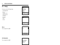
O2 heat current
Temp. Exhaust
Pos. Prim. airfl.
The position of the primary air choke is displayed in %.
2,5A
195°C
Pos. Sec. airfl.
The position of the secondary air choke is displayed in %.
O2 signal
Back
The O2 signal of the lambda sensor is displayed in %.
Fig. 79
O2 heat current
The O2 heat current of the lambda sensor is displayed in A.
Temp. Exhaust
The current flue gas temperature is displayed in °C.
38