1
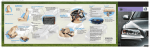
Autoplugin Key-V3
Version 9.1
User Manual
Rev. A
2
Table of Contents
Description …………………………….………………………………………
Module’s Possibilities ………………………………………..………………..
Package Content ………………………………………………………………..
Connection ……………………………………………………………………..
Basic Functions ………………………………………………………………...
Additional Functions ………….………………………………………………..
Troubleshooting …………………………………………………………….….
Glossary
CAN - Control Area Network (digital network for data transfer in vehicles)
CIP - Combined Instrument Panel
PCC – Personal Car Communicator
3
3
3
3
4
4
7
3
Description
The Autoplugin Key-V3 is electronic module designed to add a remote control
ability to the fuel-fired heater (parking heater, fuel operated heater, pre-heater),
factory installed in Volvo С30 (200?-2013), S40 (200?-2012), V50 (200?-2012) or
C70 (200?-2013). The device is plugged into the OBD-II service connector, placed
on the dashboard, and controls the heater via CAN-bus.
Module’s Possibilities
· Immediate start of the heater with Volvo car’s key. The remote control
key with 5 buttons or the PCC with 6 buttons can be used for the heater
control
· Immediate stop of the heater with Volvo car’s key
· Indication of heater’s autonomous operation with the direction indicators
flashing in the rearview mirrors.
· Additional protection of the main battery from discharging inspecting
voltage level and time of autonomous operation of the heater
Package Content
1. Autoplugin Key-V3 cartridge
2. User Manual brochure
Connection
The module needs that 2 timers and direct start / stop function for the heater
control are present in CIP. Therefore it may be necessary to load the special
software to the CIP at first by the means of Volvo dealer’s equipment.
Autoplugin Key does not need professional installation. Find OBD-II service
connector at the left lower point of the dashboard. The connector is placed near to
the handle for bonnet opening. Take the module to your hand with the LED,
oriented closer to the driver’s door side, and then gently push it to the OBD-II
connector. LED starts flashing for approximately 10 seconds, waiting for
information from CAN-bus. Wait until the LED stops flashing before the
operation. Turn the ignition on if the LED continues flashing after 10 seconds
expired.
4
Basic Functions
1. A special combination of buttons’ presses is used to start the heater with the
remote control key. Firstly press “Lamp” button on the key to switch on the
car’s lighting. Then press “Lock” button twice within 30 seconds, while
lighting is on. Every “Lock” button’s pressing is confirmed with direction
indicators flashing.
2. To stop the heater with the remote control key, switch on and then switch off
car’s lighting twice. Intervals between “Lamp” button presses should not
exceed 20 seconds.
3. It is possible remotely disable startups of the heater, programmed in the CIP.
Use remote control key to send stop command when the heater is idle.
Starting the heater any way or turning the ignition to “on” position enables
CIP timers again.
Additional Functions
By default RCP adjusted to perform only basic functions, such as start and
stop of the heater using the remote control key. To turn on the additional functions
such as battery monitoring, flashing with direction indicators in rearview mirrors,
etc. enter the module into Setup mode and activate corresponding setup item (see
settings table 3).
The buttons of the left-hand stalk switch and the brakes pedal are used to
enter Setup mode and to change the settings. It is necessary to stop the engine and
the heater before. Turn the ignition on by holding engine start button for at least 2
seconds, then press and hold the brakes pedal. Rotate the thumbwheel some steps
to select idle display in the CIP. Then press and hold for at least 5 seconds “Read”
button (“OK” button in some cars), while module’s LED flashes once a second.
Both direction indicators in the CIP confirm entering to the setup mode with 2
flashes*. Release the brakes pedal and “Read/OK” button finally.
Each setup item in the settings table is a 3-digit code. To enter a digit of a
code, shortly press “RESET” button so much times, as corresponds to a digit. The
LED and the direction indicators symbols in the CIP confirm each button press: the
LED briefly goes off, the left direction indicator flashes one time when the first or
the third digit of code is entered, the right direction indicator - when the second
digit of code is entered. To complete a digit entering, press and release “Read/OK”
button. The CIP confirms it with one flash of both direction indicators
simultaneously. When all three digits entered, the module checks the code for
validity and confirms it with the direction indicators flashing. The both direction
indicators flash twice simultaneously in case of valid code and flash twice
alternately in case of invalid code.
5
If entered digit is not correct, press and release “Read/OK” button until the module
indicates an error. Enter the code once more in that case. Several codes can be
entered without exit of setup mode.
Turn the ignition off to exit setup mode. New settings are saved in the nonvolatile
memory of the module and stored there regardless of whether the module is
connected or not. Note: If you start the engine without exit Setup mode, new
settings will not be saved in memory.
To reset the module to the factory settings, enter the code 8.1.1. Both direction
indicators in the CIP should flash three times, confirming command execution.
Then the module exits Setup mode and restarts.
Settings table (1)
Settings
Group
1.
Heater’s
operation
time
Settings
Item
1.1. Limitation of
heater’s total
operational time in
pre-heat mode
2.1. “Lock” and
“Lamp” buttons’
functions for the
heater control
1.1.1 *Not adjusted
1.1.2 40 minutes
1.1.3 50 minutes
1.1.4 60 minutes
1.1.5 70 minutes
1.1.6 80 minutes
1.1.7 90 minutes
1.1.8 100 minutes
1.1.9 120 minutes
1.2.1 10 minutes
1.2.2 15 minutes
1.2.3 20 minutes
1.2.4 25 minutes
1.2.5 30 minutes
1.2.6 40 minutes
1.2.7 50 minutes
1.2.8 60 minutes
1.2.9 *70 minutes
2.1.1 *”Lock” button for the heater start,
“Lamp” button for the heater stop
2.1.2 “Lamp” button for the heater start,
“Lock” button for the heater stop
2.2. Number of
sequential “Lamp”
button presses for
the heater control
2.2.1
2.2.2
2.2.3
2.2.4
2.3. Number of
sequential “Lock”
button presses for
2.3.1 Combination is disabled
2.3.2 *Two presses
2.3.3 Three presses
1.2. Limitation of
heater’s 1-cycle
operational time in
pre-heat mode
2.
Heater
control with
remote
control key
Possible Values
Combination is disabled
*Four presses
Six presses
Eight presses
6
3.
Battery
Monitoring
the heater control
(with the car’s
lighting turned on)
3.1.
Minimal battery
voltage that lets the
module start the
heater in pre-heat
mode
3.2.
Minimal battery
voltage that lets the
module keep
operating the heater
in pre-heat mode 1
6.
Indication
with
direction
indicators in
the rearview
mirrors
8.
Service
menu
6.1. Indication of
the heater’s startup
6.2. Indication of
command reception
from a remote
control
6.3. Indication of
the heater’s
operation, when
starting source is
the remote control
6.4. Indication of
the heater’s
operation, when
starting source is
the CIP (direct or
timer start)
8.1. Default Settings
2.3.4 Four presses
3.1.1
3.1.2
3.1.3
3.1.4
3.1.5
3.1.6
3.1.7
3.1.8
3.1.9
3.2.1
3.2.2
3.2.3
3.2.4
3.2.5
3.2.6
3.2.7
3.2.8
6.1.1
6.1.2
6.2.1
6.2.2
* Not adjusted
11.8V
11.8V
11.9V
12.0V
12.1V
12.2V
12.3V
12.4V
* Not adjusted
11.4V
11.5V
11.6V
11.7V
11.8V
11.9V
12.0V
*Off
Five flashes
*Off
Three flashes
6.3.1 *Off
6.3.2 On
6.4.1 *Off
6.4.2 On
8.1.1 Apply factory settings
* Factory setting
Recommended settings marked in Italics
1
–The module turns off the heater if battery’s voltage lowers to the adjusted limit
7
Troubleshooting
If a run-time error occurs during the heater’s operation, Autoplugin Key informs
about the error code with LED flashing. The number of flashes corresponds to the
error code. See table 2 for the error’s description and possible solutions.
Table 2
Error
Error
Possible Reasons of
Solutions
Code
Description
Error Appearance
2
No answer
Outer temperature is
The heater operates only at
from the
higher than +15 Celsius temperatures below +15°C. It
heater
degrees
is the heater manufacturer's
followed the
restriction
start
Fuel level in the fuel
Refuel the vehicle
command
tank is close to empty
(“Fuel Low” warning
indicator is illuminated
in the CIP)
The heater is blocked
Try to start the heater in the
after 3 unsuccessful
CIP menu. If it doesn’t start
starts
up, make diagnostics of the
heater.
3
Battery low
The module has
Charge vehicle’s battery with
determined that the
special charger (or start engine
battery’s voltage is
to charge) or cancel 3.1/3.2
below the specified by
module’s settings
settings items 3.1 or 3.2
4
Time limits
Time limit for
Run the engine or cancel 1.1
exceeded
autonomous operation of module’s settings
the heater is achieved
5
Unsuccessful The heater was switched Make diagnostics of the heater
start
off spontaneously at
if the error appears again
starting
6
Operation
The heater was switched Make diagnostics of the heater
cycle too
off spontaneously
if the error appears again
short
8
CAN-bus
There is a problem with Check for the module’s
error
module’s connection to
connection
the CAN-bus
9
Settings error Settings have been
Reset the settings (8.1.1),
stored in the module’s
readjust the module
memory incorrectly
11
Heater no
The heater is unplugged Make diagnostics of the heater
connection
or out of order
8
© Autoplugin ES
www.autoplugin.ru