1
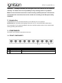
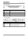
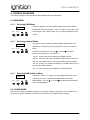
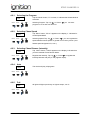
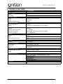
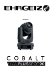
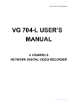
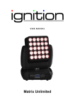
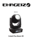
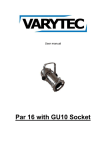
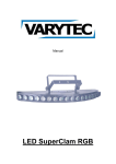
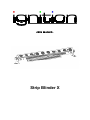
USER MANUAL
Strip Blinder X
STRIP BLINDER X
Table of contents
1. Safety instructions .................................................................... Fehler! Textmarke nicht definiert. 1.1. FOR SAFE AND EFFICIENT OPERATION ..................... Fehler! Textmarke nicht definiert. 2/2
STRIP BLINDER X
The manual contains complete information about the item and how to operate with the device. Please
once again make sure to that you read the operation instruction and safety information before using
the device. Throughout the manual the following conventions are used distinguishing the elements of
text:
S CAUTION: Identifies important information which should be followed to avoid damage of device
S NOTE: Provides additional hints or information that requires special attention.
Menu names, command, icon or button that you can see is shown in bold style.
1. SAFETY INSTRUCTION
A NOTICE
All modifications to the device will void the warranty and installation and repairs are
to carry out by skilled personnel only.
A CAUTION
Avoid looking directly into the source of light. It may cause epileptic seizures. Avoid
touching the item when ON, the housing can reach a high temperature from the
heat developed by the high power LED.
1.1. FOR SAFE INSTALLATION AND EFFICIENT OPERATION
1.1.1. Use of the item as intended
•
The Strip Blinder X is designed for use on stages, in discotheques and for architectural
illumination. The device is approved only for a connection up to a maximum of 230 V AC,
50Hz.
•
The ambient temperature must be between 32°F /0°C and 104°F /40°C. Avoid exposing the
device to direct rays of the sun or next to a heating appliance. This also applies for
transportation in closed vehicles.
•
The device may only be operated at a level between -20 and 2000m NN.
•
The symbol
stands for the min distance between the item and objects. The distance
between light source and surface should not be less than 1.5 m. Make sure that there is 50
cm space around the item for good ventilation.
•
Regular stoppages increase the life of your device.
•
Avoid shakes and every form of violence during the installation or usage.
•
Make sure that the device is not exposed to extreme heat, humidity or dust at the installation
spot. Make sure that cables do not lie around. This would decrease your own safety and the
safety of third parties.
•
Do not operate the device during thunderstorms. Overvoltage could destroy the device.
Disconnect the device during thunderstorms completely from the grid by pulling the mains
plug.
•
Avoid looking directly into the source of light. It may cause epileptic seizures. This applies in
particular for people where epileptic seizure has been diagnosed by a doctor.
3/3
STRIP BLINDER X
•
Power cable, never pull the power cable to remove the plug from the receptacle, be sure to
hold the plug. When not using the device for an extended period of time, be sure to disconnect
the plug from the receptacle.
•
Make sure that the area under the item is blocked, while mounting it or working on it.
•
When cleaning, use a clean dry cloth to wipe off the dust, or a wet soft cloth for stubborn dirt.
A NOTE
After taking the device from a warm to a cold room, it may not be put into operation.
The resulting condensation can possibly destroy the device. Do not turn on the device
until it has reached ambient temperature.
A NOTE
Damages caused by the disregard of this user manual are not subject to warranty.
The dealer will not accept liability for any resulting defects or problems. Make sure the
electrical connection is carried out by qualified personnel. All electrical and mechanical
connections have to be carried out according to the European safety standards.
This device falls under the protection class I. It is necessary to follow the instructions.
1.1.2. Overhead rigging
The suspension devices have to be build and measured so they can withstand for an hour the tenfold
of the payload without suffering a permanent detrimental deformation. Basically installation has to be
made by using a second separate suspension. This can be e.g. a suitable net. The second
suspension must be designed and attached so no part of the installation can fall down in case of
failure. The maximum drop distance must never exceed 20 cm.
During construction, reconstruction and deconstruction unnecessary stay in the range of moving
areas, on lightning bridges, under elevated work stations or any other danger zones is forbidden.
Before taking the device in operation, the installation must be approved by an expert. The operator is
obliged to get an expert to check safety-related and mechanical facilities at least once a year.
A NOTE
Overhead installation requires a high level of experience. This includes knowledge of
calculating the payload, used installation material and safety inspections of the used
installation material and the projector whereas the required experience is not limited to
this. Do not try to carry out installation yourself under any circumstances if you are not
qualified. Contact a professional installer. An inappropriate installation can lead to
injuries and/or damaged properties.
If the projector may hang from the ceiling or from high beams, the use of truss systems is mandatory.
The projector may not be installed so it can swing freely in the room.
A CAUTION
Crashing down items can cause serious injuries! Do not install the projector, if you
doubt the safety of a possible installation form!
4/4
STRIP BLINDER X
A CAUTION
When rigging the device, make sure there is no highly-inflammable material
(decoration articles, etc.) within a distance of min. 1.5 m.
Mount the projector with the mounting-bracket to your trussing system using an appropriate clamp.
During overhead installation the projector must be always secured by a safety rope which is designed
to hold the twelvefold weight of the device. Only safety ropes with quick-release safety fastener
elements may be used. Hang up the safety rope in the hole of the mounting bracket. Direct the rope
over the truss or an appropriate fastening point. Hang up the end in the fastening element and tie up
the locking nut. A safety rope once exposed to falling load or damaged may not be used furthermore.
Adjust the desired inclination angle via the mounting-bracket and tighten the screw.
1.1.3. Power connection
Before connecting the item to the main plug, connect the wires to a suitable power plug. The voltage
and frequency must exactly be the same as stated on the device and makes sure that the power plug
is always inserted without force.
Wires: Brown (L), Blue (N), Yellow/Green (
A NOTE
)
The connection of the earth wire is strictly recommended! Never leave this device
running unattended! Every person that is involved with this item has to be qualified!
If you want to connect the item direct to the common main power grid, the installation of a separator
with at least a 3 mm contact hole for each pole is necessary. The connection is exclusively permitted
for electrical installation which complies with the VDE-regulations DIN VDE 0100. Indoor installation
must be equipped with an earth leakage circuit breaker (RCD) with 30 mA rated current.
1.1.4. Cleaning and Maintenance
Contaminations like dust should be removed regularly from the device. Use a damp, lint free, cloth. Do
not use alcohol or solvents under any circumstances. Please make sure that safety-related and
mechanical facilities are inspected by a skilled person once a year.
•
Ensure all screws attached to the device or parts of the device are very tight and not
corroded.
•
Make sure there are no deformations of the housing, attachment and installation spot.
This also includes the ceiling, the suspension and the truss.
•
Electrical connection cables may not have any damages, depositions or signs of material
fatigue e.g. porous connections.
5/5
STRIP BLINDER X
Important:
Damages caused by the disregard of this user manual are not subject to
warranty. The dealer will not accept liability for any resulting defects or problems.
Make sure the electrical connection is carried out by qualified personnel. All electrical
and mechanical connections have to be carried out according to the European safety
standards.
2. Introduction
Congratulations to your purchase and thank you for selecting one of our products.
Strip Blinder X is a powerful silent lighting device with 10 pcs. conventional Warm White lamps,
GU10 230/75W. For successful installation and secure operation please read the user manual before
starting operating with the device.
3. COMPONENTS
Introduction to the external components of the item. 3.1. FRONT COMPONENTS
Ref.
Component
1
Lamps
2
Front screws
Description
10 pcs conventional Warm White lamps, GU10 230/75W
Holding the front panel
6/6
STRIP BLINDER X
3.2. SIDE COMPONENTS
Ref.
Component
Description
1
Housing
2
DMX in
The connector sending signal to the device. XLR 3-PIN Neutrik,
3
Power in
AC 230V – 50/60 Hz, Max 20, power in through the connector.
4
Power Out
5
DMX out
The signal out of the device. XLR 3-PIN Neutrik,
6
Air gaps
Conventional cooling system requires a large number of air gaps.
Two parts aluminum housing. Main housing storing the 10pcs GU10
lamps.
AC 230V – 50/60 Hz, Max 20, power out through the connector.
3.3. BACK COMPONENTS
Ref.
Component
1
Mode
Description
Selecting Mode
Activating various functions in DMX mode, dimmer (initial on the
2
Menu
display d), Program (P) and Speed with (SP)
In DMX mode the button “Menu” helps you selecting between
functions, DMX Address (A) and Channel (CH)
7/7
STRIP BLINDER X
4. OPERATION MODES
The device operates in two operating modes, DMX Mode and Chase Mode.
4.1. DMX MODE
4.1.1.
Selecting DMX Mode
If letter "A" appears, means that DMX address and shows that the
A 001
DMX Mode has been activated. Letter "P" means that you are in the
Mode
Chase Mode. With “Mode” button can you change between the two
Menu
4.1.2.
modes.
Selecting Channel Mode
Tap “Menu” button to select to Channel Mode. When letters "CH"
CH:01
followed by 2 numbers (01,02,05,10) than you are on the Channel
Mode
Mode.
Menu
Channel Value Selection: Tap “Up
” or “Down
” to select
between the channel 01, 02, 05 and 10.
“CH:01”, all channels are controlled by one DMX channel.
“CH:02”, channel 1 and 2 are controlled by DMX channel, channel 3
and 4 by other DMX channel. You have 5 DMX channels available.
“CH: 05”, channel 1 to 5 will be controlled by one DMX channel, the 6
to 10 by other DMX Channel.
“CH :10”, each channel is controlled by one DMX Channel.
4.1.3.
Selecting DMX Address Mode
Tap “Menu” button, “ A “ appears on the display following by three
A:001
numbers 001 to 512, it indicates the DMX Mode is activated.
Mode
DMX address: Tap “Up
Menu
” or “Down
” to select between the 001
and 512 DMX-address.
4.2. CHASE MODE
The unit has 16 built in programs (except Auto and Full). Creating a light show you can select any of
the build-in programs and also can control the speed which the program will be chasing.
8/8
STRIP BLINDER X
4.2.1.
Selecting the Program
Tap the “Mode” button, "P" is shown, it indicates that Chase Mode is
P:01
activated.
Mode
Selecting Program: Tap “Up
Menu
” or “Down
” you can enter
program 01 to 16 and Auto and Full.
4.2.2.
Selecting Chase Speed
Tap “Menu” button, "SP:01" appears on the display, it indicates for
SP:01
Chase Speed Mode.
Mode
Selecting Speed: Tap “Up
Menu
” or “Down
” you can regulate the
speed between lowest speed 01 (speed of once every 30 sec.) and
4.2.3.
fastest speed 99 (speed of 0,1 sec.).
Selecting Chase Dimmer (Intensity)
Tap “Menu” button, "d:000" appears on the display, indication that
d:000
you have entered Chase Dimmer Mode.
Mode
Regulate the Intensity: Tap “Up
Menu
” or “Down
” to regulate the
intensity between 000 (Off) to 100 (highest output).
4.2.4.
Auto
The device will play all programs.
AUTO
Mode
Menu
4.2.5.
Full
All lights will light up and stay on highest output, 100 %.
FULL
Mode
Menu
9/9
STRIP BLINDER X
5. PRODUCT FEATURES
Type
Strip Blinder X
Optical System
Optics
Beam angle
LED source of light
Lamps
Colors
Lifetime according to use
Temperature ranges
Ambient temperature
Item Number
N/A
30°
10PCS × GU10 230V/75W
Warm white
~1500hr
0℃/40℃
Conventional cooling system through airgaps
Cooling
Control & Programming
Protocol
DMX512 Control Channels
Stand alone functions
DMX512 Connection
Housing
Material
DMX512
1, 2, 5 and 10.
DMX MODE, Programs, Dimming and Speed
XLR 3-PIN Neutrik,
Color
Black
Housing protection class
IP20
Mounting
Mounting
Technical specification
Power supply
SPCC
Floor bracket
AC 230V/50Hz Max.16A
Power input
Fuse
Max.780W
F6.3A 250V
Measurements/Weight
Measurements(L X W X H)
1000mm x 78mm x 130mm
Weight
7.0kg
Included accessories
H05VV-F 3G1.5mm², 1.5M with Powercon (1pcs)
Wing screw (2pcs)
Grommet (2pcs)
Washer(2pcs)
Bracket holder(2pcs)
Accessories
N/A
10 / 10
STRIP BLINDER X
Importer:
B&K Braun GmbH
Industriestraße 1
D-76307 Karlsbad-Ittersbach
www.bkbraun.com
[email protected]
11 / 11