1
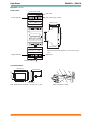
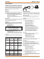
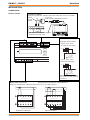
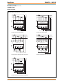
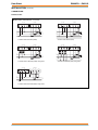
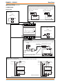
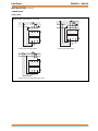
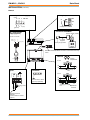
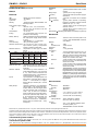
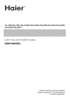
Data Sheet
EM-MPO/.., ENC2/S
Multi-Parameter Electricity Meters and Node Controller
EM-MPO/.., ENC2/S Multi-Parameter
Electricity Meters and Node Controller
Description
Features
EM/MPO/..
• Multi-parameter metering
• Range of units available
• Fully configurable
• Class 1 accuracy (/STAR3DIN, /STAR3 only)
• Selectable backlit LCD display
• Programmable CT and VT ratios
• Split ring CTs available
• Through panel or DIN rail mounting versions
• Optional panel mounting kits for DIN mounting versions
• RS485 to network interface (ENC2/S)
• Polarity independent CT connections (except cogeneration)
• Suitable for use with VTs (except /SIRIO)
The EM-MPO/... is a range of 3 phase, multi-parameter electricity
meters. The /STAR3 is a through panel mounted unit with a high
visibility red on black LCD digital display. The /STAR3DIN is a DIN
rail mounted unit with a dot matrix LCD display. The /SIRIO is a
DIN rail mounted economy version with a 128 segment (8 digit)
LCD display. All three units require 5 A current transformers.
Voltage transformers may be used on /STAR3 and /STAR3DIN
for medium voltage measurements. The required transformer
ratios are programmable from the panel. An RS485 connector
cable links the EM-MPO/... to the ENC2/S’s RS485/RS232
converter. Used in conjunction with the network interface (ENC2/S,
Electricity Meter Node Controller) all logged data can be accessed
directly over the IQ system network. Ideal for applications where
analysis of electricity supplies is required, especially on large
industrial or commercial sites.
ENC2/S
The Electricity Meter Node Controller (ENC2/S) allows the data
measured by the EM-MPO/... to be accessed by IQ system
devices over the IQ system current loop network. It is available
in an IP30 enclosure (NBOX) with two input power supply
versions (230 Vac or 24 Vac/dc).
• Standard IQ Configuration modules
• Automatic network test
• 116 node addressable
Physical
72 mm (2.84”)
46 mm (1.18”)
ACC/STAR3DIN/PANELKIT (EM-MPO/STAR3DIN Meter Panel Mounting Kit)
185 mm (7.28”)
83 mm (3.27”)
159 mm (6.26”)
6 mm (0.24”)
Note: Panel cutout for kit 180 x 46 mm (7.09” x 1.18”)
EM-MPO/.., ENC2/S Data Sheet TA200268 Issue 3 09/07/08
Detail of assembly to meter
1
EM-MPO/.., ENC2/S
Physical
Data Sheet
( continued)
connect to ENC2/S
EM-MPO/STAR3DIN
current terminals
input power supply to meter
P1 P2
P1 P2
P1 P2
AL1
AL2
AL3
CURRENT INPUT MAX 7A~
!
1
2
A B
RS485
0V~
230V~
115V~
!
44 mm (1.73”)
4VA~ 50/60Hz
POWER SUPPLY
MULTI PANEL METER
PAG
10Wh
SEL
SET
90 mm (3.54”)
STAR3 din
46 mm (1.18”)
48 mm (1.89”)
58 mm (2.28”)
VOLTAGE INPUT MAX 600 V ~ CAT 111
VL1
N
VL2
N
VL3
N
meter front panel cutout
dimensions 158.5 mm x 46 mm
(6.24” x 1.81”)
!
voltage terminals
157.5 mm (6.2”) (9 DIN module)
14.5 mm (0.57”)
EM-MPO/STAR3
100.9 mm (3.97”)
96 mm (3.78”)
STAR3
Three phase energy analyzer
PAG
SEL
SET
buttons under flap
115.4 mm (4.54”)
96 mm (3.78”)
panel mounting spring
connect to
ENC2/S
digital outputs
1
2
3
4
5
6
1
2
3
A
B
OUT
1A
4
5
OUT OUT
1B 2A
meter front panel cutout dimensions 91 mm x 91 mm (3.58”
3.58”)
6
OUT
2B
RS485
VL3
VL2
VL1
N
1
2
3
4
AL3 AL2 AL1 COM 0
115 230V~
input power supply to meter
!
VOLTAGE INPUT
MAX 600V~
CAT 111
voltage terminals
2
5 6 7 8
9 10 11
!
!
CURRENT INPUT POWER SUPPLY
MAX 5A~
50/60Hz 6VA
current terminals
EM-MPO/.., ENC2/S Data Sheet TA200268 Issue 3 09/07/08
Data Sheet
Physical
EM-MPO/.., ENC2/S
(continued)
EM-MPO/SIRIO
70 mm (2.76”) (4DIN
module)
relay output
input power supply to meter
current terminals
115V~
C AL1 AL2AL3 3 4
0V~
230V~
CURRENT INPUT RELAY POWER SUPPLY
!
MAX 7A ~
1A-250V~ 3VA~50/60Hz
!
44 mm (1.73”)
Energy Meter
10Wh
PAG
SEL
SET
46 mm (1.81”)
Sirio
90 mm (3.54”)
48 mm (1.89”)
58 mm (2.28”)
!
VOLTAGE INPUT
MAX 450V~
Rs485
N VL1 VL2 VL3
A
B
1
2
voltage terminals
meter front panel cutout dimension 71 mm x 46 mm (2.8” x
1.81”)
digital output
connect to ENC2/S
ACC/SIRIO/PANELKIT
65 mm (2.56”)
70 mm (2.76”)
46 mm (1.81”)
94 mm (3.7”)
71 mm (2.8”)
3 mm (0.12”)
Note: Panel cutout for kit 88 mm x 49 mm (3.46” x 1.93”)
EM-MPO/.., ENC2/S Data Sheet TA200268 Issue 3 09/07/08
Detail of assembly to meter
3
EM-MPO/.., ENC2/S
Physical
Data Sheet
(continued)
ENC2/S
230 Vac
input power
supply option
SPCO relay (digital output)
connection to EM-MPO/..
NC NO C
~
RS232/485 converter
24 Vac or dc
input power
supply option
~
24V
MODEM
RDS/RS232
136 mm (5.35”)
!
adaptor cable
(40 mm, 1.57”),
supplied
16 mm
(0.63”)
33 mm (1.3”)
adaptor cable
(3 m, 9’ 10”),
supplied
9 Way D type
25 Way D type
33 mm (1.3”)
230V
210 mm (8.27”)
9 Way D type
relay O/P
LED
status LEDs
OK
input LEDs
TX
1
RX
Trend Lan
LEDs
2
1 2 3 4 5 6 7 8 9 10
inputs
230 mm (9.06”)
earth bus
4
Trend Lan
connector
70 mm (2.76”)
address/baud rate switch
EM-MPO/.., ENC2/S Data Sheet TA200268 Issue 3 09/07/08
Data Sheet
EM-MPO/.., ENC2/S
FUNCTIONALITY
The EM-MPO/.. and the ENC2/S together provide electricity
measurements which can be accessed by IQ system devices.
The EM-MPO/.. takes the measurements and sends them to the
ENC2/S in standard RS485 interface protocol. ENC2/S stores
this data in memory and calculates further measurements. IQ
system devices can then read the measurements from the
ENC2/S using IQ system network communications.
ENC2/S
Network
Supervisor
EM-MPO/..
Front panels
All EM-MPO/.. units have an LED display on which to display the
measured parameters, and to enable the unit to be configured.
They also have three pushbuttons PAG, SEL, and SET.
PAG: This steps though the parameter types (e.g. V, A, W)
SEL: This selects parameters within the type (e.g. for
current: Al, Aneutral, Alaverage)
SET: This is used to configure the unit.
PAG+SEL: This combination will enter configuration mode
on the unit.
RS485 Output
The unit provides a standard RS485 output to transmit the
measurements to the ENC2/S which can be up to 3 m away (set
by default for ENC2/S communications)
Configuration
All EM-MPO/.. units have the following parameters configured by
default with the correct settings for communication with the
ENC2/S. If they have been changed then they should be returned
to the following settings:
RS485 Baud Rate: 9600
RS485 Parity: None
RS485 Address (modbus): 1
ALL EM-MPO UNITS MUST HAVE THE RS485
PROTOCOL CONFIGURED FOR ASCII
Their protocols are configured by default for IEEE,
and must be changed to ASCII
All meters need to be configured to cater for:
Voltage transformers (cannot be used on /SIRIO)
Current transformers
Connection type (e.g. 3 phase (delta), 3 phase +neutral
(star), 2 phase with neutral, Single phase with neutral).
Configuration mode also enables the counters and the averages
to be reset.
The table below indicates the major differences between the 3
meters.
/STAR3DIN
/STAR3
33
33
Parameters sent
to ENC2/S
/SIRIO
32
(not -ve 3 Phase
Energy)
Parameters
displayed on
meter
33 transmitted
plus 16
33 transmitted
plus 10
Accuracy
<0.5%:
V, I, Power
<0.5%:
V, I, Power
1%: V, I
2%: Power
Fixing
DIN rail
(panel kit
available)
Front panel
DIN rail
(panel kit available)
Max Volts
430 Vac phase
to neutral
600 Vac phase
to phase
(Use VTs for
greater volts)
430 Vac phase
to neutral
600 Vac phase
to phase
(Use VTs for
greater volts)
7
264 Vac phase to
neutral
450 Vac phase to
phase
V Ts
yes
yes
no
Cogeneration
yes
yes
no
Display
Dot matrix LCD
multi-segment
bright red on
black LCD
8 digit LCD
Digital Outputs
none
2 electronic
1 electronic
1 mehanical
Consumption
4 VA
4 VA
3 VA
EM-MPO/.., ENC2/S Data Sheet TA200268 Issue 3 09/07/08
EM-MPO/STAR3DIN
The EM-MPO/STAR3DIN is a DIN rail mounted high quality energy
analyser with a dot matrix LCD display. A mounting kit is available
to facilitate front panel mounting (ACC/STAR3DIN/PANELKIT)
Input Power Supply
The EM-MPO/STAR3DIN requires 230 Vac (fused at 100 mAT)
or 115 Vac (fused at 200 maT), 35 to 400 Hz, at 4VA.
Parameters
In addition to the parameters delivered to the ENC2/S, the unit can
display:
Minimum Phase voltages Vln (V)
Maximum Phase voltages Vln (V)
Phase to Phase Voltages Vlx-Vly (V)
Minimum Phase Currents (A)
Maximum Phase Currents (A)
Neutral Current (A) - Star only
Average Phase Currents (A)
Maximum Demand Phase Currents (A)
Total Maximum Demand Power (kW)
Total Maximum Demand Apparent Power (kVA)
Total Maximum Demand Reactive power (VAr)
Positive 3 Phase Apparent Energy Counter (kVAh)
Phase Voltage Total Harmonic Distortions (%)
Total Voltage Total Harmonic Distortion (%)
Phase Current Total Harmonic Distortions (%)
Total Current Total Harmonic distortion (%)
Connection
The unit can be connected in the following configurations:
Single Phase with neutral (1CT)
2 Phase with neutral (2CTs) Diphase
3 Phase (3CTs) Delta
3 Phase with Neutral (3CTs) Star
3 Phase using 2 VTs (3CTs) Delta
3 Phase using 2 CTs (2CTs) Delta
Voltage transformers can be used in all configurations, 1 VT for
each phase (except for 3 phase delta using 2 VTs)
Configuration
The following settings must be configured:
RS485: Default baud rate and parity settings OK, see above.
Protocol must be changed from IEEE to ASCII
RS485 address (modbus): Default setting OK, see above
VTs: If used must be set up. If not used set ratio to 1 (default)
CTs: Must be set up.
Connection: set up to one of the following:
Delta: 3 phase without neutral
Star: 3 phase with neutral
Diphase: 2 phase with neutral
Single-phase: 1 phase with neutral
The set up pages may also be used to:
Set integration time for calculation of average current
and power (0 to 99 minutes, default 15 minutes)
Reset energy counters
Reset averages and maximum demands
Enable/Disable cogeneration counters (note that to
measure cogeneration properly the CTs must be connected in
the same direction)
5
EM-MPO/.., ENC2/S
FUNCTIONALITY
Data Sheet
(continued)
EM-MPO/STAR3
The EM-MPO/STAR3 is a front panel mounted energy analyser
with a multi-segment bright red on black LCD display. It has two
digital outputs for measurement pulses, or alarm indication.
Input Power Supply
The EM-MPO/STAR3 requires 230 Vac or 115 Vac, 35 to 400 Hz,
at 4VA.
Parameters
In addition to the parameters delivered to the ENC2/S, the unit can
display:
Phase to Phase Voltages Vlx-Vly (V)
Neutral Current (A) - Star only
Average Phase Currents (A)
Maximum Demand Phase Currents (A)
Total Maximum Demand Power (kW)
Total Maximum Demand Apparent Power (kVA)
Phase Voltage Total Harmonic Distortions (%)
Total Voltage Total Harmonic Distortion (%)
Phase Current Total Harmonic Distortions (%)
Total Current Total Harmonic distortion (%)
Connection
The unit can be connected in the following configurations:
Single Phase with neutral (1CT)
2 Phase with neutral (2CTs) Diphase
3 Phase (3CTs) Delta
3 Phase with Neutral (3CTs) Star
3 Phase using 2 CTs (2CTs) Delta
CTs must be used. VTs can be used in all configurations., 1 VT
for each phase.
Configuration
The following settings must be configured:
RS485: Default baud rate and parity settings OK, see above.
Protocol must be changed from IEEE to ASCII
RS485 address (modbus): Default setting OK, see above
VTs: If used must be set up. If not used set ratio to 1 (default)
CTs: Must be set up.
Connection: set up to one of the following:
Delta: 3 phase without neutral
Star: 3 phase with neutral
Diphase: 2 phase with neutral
Single-phase: 1 phase with neutral
Pulse Modes
The outputs can be set individually to be sourced from one of the
following parameters:
+ve 3 Phase Active Energy consumed (kWh)
-ve 3 Phase Energy (kWh)
+ve 3 Phase Reactive Energy (kVArh)
-ve 3 Phase Reactive Energy (kVArh)
3 Phase Apparent Energy (kVAh)
Each output also requires the value (‘weight’) of each pulse to
be defined (e.g. 0.01 kWh/pulse)
Relay Mode
Note that it is possible to configure relay 1 to be controlled from the
RS485 bus, but this feature is not available when the ENC2/S is
connected.
The outputs can be set individually to indicate an alarm condition
from one of the following parameters: Total Voltage or Phase
Voltage, VLN, (V)
Total Current or Phase Current, ALN, (A)
Total Power or Phase Power (W)
Total Apparent Power or Phase Apparent Power (VA)
Total Reactive Power or Phase Reactive power (VAr)
Total Power Factor or Phase Power Factor (cos ø)
Total THD voltage or Phase THD voltage (%)
Total THD current of Phase THD current (%)
When used as an alarm indication each output should be configured
with the following settings:
High alarm threshold
Low Alarm threshold
Hysteresis:
The alarm condition is registered only if the value rises
above the threshold by the percentage set
Delay: The alarm condition is registered only if the alarm
persists for longer than the alarm delay (000 to 999 s)
The set up pages may also be used to:
Set integration time for calculation of average current
and power (0 to 99 minutes, default 15 minutes)
Reset energy counters
Reset averages and maximum demands
Enable/Disable cogeneration counters (note that to
measure cogeneration properly the CTs must be
connected in the same direction)
Alarm Outputs: The two alarm outputs can be set to either:
100 ms pulse mode
20 ms pulse mode
Relay mode
This setting applies to both outputs, they cannot be set individually.
6
EM-MPO/.., ENC2/S Data Sheet TA200268 Issue 3 09/07/08
Data Sheet
FUNCTIONALITY
EM-MPO/.., ENC2/S
(continued)
EM-MPO/SIRIO
The EM-MPO/SIRIO is a DIN rail mounting multiparameter meter
with an 8 digit LCD display.
Input Power Supply
The EM-MPO/SIRIO requires 230 Vac or 115 Vac, 35 to 400 Hz,
at 3 VA
Parameters
It displays the following parameters:
Mean Line Voltage (V)
Main Phase Current (I)
Total Active Power (W)
Total Power factor (Cos ø)
Average Active Power (W)
Maximum Demand Active Power (W)
Active Energy Counter (Wh)
The display selection is slightly different to the previous two
meters.
The PAG key steps though three display pages, Voltage/Current,
Active Power/Power Factor, and Active Energy Counter. With
the Active Power/Power Factor selected, pressing the SEL key
steps through the other pages, Average Active Power, Max.
Dem. Active Power, and back to Active Power/Power Factor.
The EM-MPO/SIRIO cannot supply the -ve 3 Phase Energy
(node 58) parameter to the ENC2/S.
Connections
It can be connected in the following configurations:
Single Phase with Neutral (1CT)
2 Phase with Neutral (2CTs) Diphase
3 Phase (3CTs) Delta
3 Phase with Neutral (3CTs) Star
3 Phase using 2CTs (2CTs) Delta
It cannot use VTs.
Pulse Modes
The outputs can be set individually to be sourced from one of the
following parameters:
3 Phase Active Energy consumed (kWh)
3 Phase Apparent Energy (kVAh)
Each output also requires the value (‘weight’) of each pulse to
be defined (1, 10, or 100/pulse)
Relay Mode
The outputs can be set individually to indicate an alarm condition
from one of the following parameters:
Total Current (A)
Total Voltage (V)
Total Power (W)
Total Power Factor (cos ø)
The mechanical alarm output can be set to either produce a level
output, or a pulse output (e.g. to trip an external contactor) under
alarm conditions.
Each relay mode output should be configured with the following
settings:
High alarm threshold
Low Alarm threshold
Hysteresis: The alarm condition is registered only if the
value rises above the threshold by the percentage set
Delay: The alarm condition is registered only if the alarm
persists for longer than the alarm delay (000 to 999 s)
Configuration
The following settings must be configured:
RS485: Default baud rate and parity settings OK, see above.
Protocol must be changed from IEEE to ASCII
RS485 address (modbus): Default setting OK, see above
CTs: Must be set up.
Connection: set up to one of the following:
Delta: 3 phase without neutral
Star: 3 phase with neutral
Diphase: 2 phase with neutral
Single-phase: 1 phase with neutral
The set up pages may also be used to:
Set integration time for calculation of average current
and power (0 to 99 minutes, default 15 minutes)
Reset energy counters
Reset averages and maximum demands
Alarm Outputs: The EM-MPO/SIRIO has two alarm outputs, one
mechanical (1 A, 250 V) and one electronic (120 mA, 100 Vac).
The two alarm outputs can be set to either:
100 ms pulse mode
20 ms pulse mode
Relay mode
This setting applies to both outputs, they cannot be set individually.
EM-MPO/.., ENC2/S Data Sheet TA200268 Issue 3 09/07/08
7
EM-MPO/.., ENC2/S
FUNCTIONALITY
Data Sheet
(continued)
ENC2/S
The ENC2/S allows an EM-MPO/... to be connected to the IQ system network. It stores values received from the meter, making them
available to other devices on the IQ system network. Some values are calculated within the ENC2/S using readings received from
the meter.
The ENC2/S consists of a customised IQ22x controller with an RS232/RS485 converter module connected to the specially modified
RS232 port, and a dedicated script program (TCL) which performs the necessary communications and calculations to produce the
measurements in the IQ controller analogue array. It also has further modules configured so that some of the measurements are
identified by label and additional measurements are calculated within the ENC2/S.
Hardware
Unit: The ENC2/S is supplied in a plastic enclosure with a
transparent plastic flip-up terminal cover. It has a 3 point mounting
to facilitate installation. It has an RS232/RS485 converter
connected by cable to the RS232 connector at the rear of the unit.
Connectors: Two part connectors are used throughout to
facilitate wiring. A busbar is provided for screen termination.
Power: 230 Vac 50/60 Hz (/230 option), 24 Vac or 24 Vdc (/24
option).
RS485 to EM-MPO/..: The RS232/RS485 converter module is
connected to the rear of the unit by means of a 40 mm 25 way
female D connector to 9 Way male D connector cable. The
converter module is connected to the EM-MPO/.. by a 3 meter
unscreened 9 way male D connector to open ends 2 wire cable.
Both of these adapter cables are supplied with the unit.
RS232 to RS485 Converter
9 W D male
9 W D male
3 m (9’ 10”)
ENC2/S
EM-MPO/..
Fusing: The controller has no replaceable fuses; protection is
provided by a self-resetting thermally protected transformer.
Indicators: LED indicators for receive and transmit network
current flow (RX, TX) and network OK ( ), also for all I/O
channels, power ( ), and watchdog ( ). See specification
section for details.
40 mm (1.57”)
25 W D female cut ends
The interface module has DIP switches which are set by default
to operate correctly with the ENC2/S EM-MPO/.. system. They
should not be changed. They are set as follows:
Network:
The 2 part network terminals facilitate connection
of 2 wire cables.
: The ENC2/S device address on the local
Address Switch
Lan is selected by address switch poles 1 to 7. The TCL program
requires that the next address (i.e. address switch setting plus
1) is also allocated to the ENC2/S. Therefore the address switch
may only be set in the range 4 to 8, 11 to 118 and both the setting
and the setting plus 1 must be unique on the local Lan.
Baud Rate Switch : The local Lan baud rate is set by address
switch poles 8 to 10 to 19k2, 9k6, or 1k2. The local Lan baud rate
must be set to match other nodes on the local Lan.
Network bypass relay: In order that the network continues to
operate if the ENC2/S fails, a node bypass relay is fitted to
maintain network integrity in the event failure of the node's
power supply, or failure of the node itself. The bypassing of a
node will be recognised by the downstream node, and reported
as a Lan Changed alarm.
Battery Backup: Details about the strategy configuration, time
and date, and logged data are stored in RAM. A plug-in lithium
cell provides power to maintain the data in the event of power
failure, or the controller being switched off.
Pole
Setting
SW1
ON
2 wire
Function
SW2
OFF
RXEN
SW3
OFF
TXEN
SW4
ON
ADE2
SW5
OFF
ADE1
SW6
OFF
ADE0
Note: The internal wiring to the rear RS232 plug is non-standard
and is only intended for the ENC2/S application. If any other
device were to be connected to this plug, damage may occur.
I/O channels: The ENC2/S is supplied with 2 digital input
channels, and 1 digital (relay) output channel.
Digital (Relay) Output
(external channel unnumbered, configuration channel OP8)
N C
N O
C
Digital only inputs
(external connection inputs and configuration channels 1,2)
5 V
y e llo w
1 K
4 7 K
IN n
C
8
0 V
EM-MPO/.., ENC2/S Data Sheet TA200268 Issue 3 09/07/08
Data Sheet
EM-MPO/.., ENC2/S
COMPATIBILITY
Supervisors:
Utility software:
Controllers:
FIRMWARE
916, 963, IQView, Viewpoint.
PowerTool, Wupdn, SET.
It can communicate to other IQ controllers
using inter-controller communications.
Strategy files: A certain amount of configuration is present in
the ENC2/S so if a strategy file is downloaded into the ENC2/S,
the pre-configured data will be lost. The IQ Configuration
Reference Manual Addendum covers the compatibility between
different types of strategy files.
Sensor Logs: The IQ Configuration Reference Manual
Addendum covers the compatibility between the ENC2/S sensor
logs and supervisors and software tools.
Compatibility of EM-MPO/.. and ENC2/S with EM/MPO2 and
EM/MPO+: The ENC2/S no longer sends current time to the meter
(i.e. meter timer has to be set manually using front panel buttons).
The following additional values are on longer received from the
EM-MPO/.. meters:
Node
Label
Range
Units
42
Red Phase Current Crest Factor
0-10
43
Yellow Phase Current Crest Factor
0-10
44
Blue Phase Current Crest Factor
0-10
59
-ve 3 Ph Reactive Energy
0-3200000 kVArh
60
Blue Phase Energy Cons
0-3200000 kWh
Note that using the current nomenclature: Red Phase ≡ L1,
Yellow Phase ≡ L2, Blue Phase ≡ L3.
Compatibility of EM-MPO/... and EM/MPO2 with EM/MPO+:
The EM/MPO+ has a fibre optic connection which is only
compatible with ENC.
The EM/MPO2 is compatible with ENC2 and ENC2/S.
The EM/MPO is only compatible with ENC/S.
By comparison with the older meters the parameter values
received from the EM/MPO meters have different units as follows:
sensors 3, 11,12,13, are W instead of kW, and sensors 14 and
15 are now VA and VAr instead of kVA and kVAr. The ranges
(i.e. maximum values that parameters can take) available in the
EM-MPO/.. and EM/MPO2 are much larger than those on the
EM/MPO+.
Compatibility with old RS232/485 converter: The old grey
converter (K485-ADE) plugged directly into the back of the
ENC2/S using its 25 Way D type). It can be plugged into the new
ENC2/S but its old cable (9 Way D female to cut ends, 2 wire,
EJ104355) must be used to connect to the EM-MPO/.., or EM-MPO2.
The firmware within the ENC2/S consists of two parts: the
device part, and the TCL part. The device part (standard IQ2v3.1
firmware) consists of a number of standard IQ system
configuration modules, and functions in exactly the same way
as an IQ Controller. Some of these modules are already
pre-configured as explained in the strategy section. The remaining
modules may be configured in the normal way. The TCL part runs
the TCL script which communicates with the EM-MPO/.., performs
necessary calculation, and places the reading into the analogue
array.
Configuration: The device part of the ENC2/S uses the standard
IQ configuration mode which enables configuration across the
network. Alternatively SET can be used but the existing special
strategy should first be uploaded before adding to it using SET.
The modified strategy can then be downloaded to the controller
by SET. SET can also be used to upload, and download IQ2 files
for backup purposes.
Communications: The ENC2/S is connected to IQ system
devices by way of the IQ system current loop network, and to
the EM-MPO/.. by way of an RS485 link.
Modules: The strategy within the device part consists of a number
of individual functional blocks known as configuration modules.
These blocks can be linked in various combination to perform
manipulation of parameters from the EM-MPO/.. and to service the
I/O. The table lists the different types of configuration modules and
the number of each type available within the ENC2/S.
Module Type
Sensor
Number
32
Module Type
Number
Critical Alarm
4
Sensor type
8
Alarm History
20
Loop
16
IC Comms
16
Function
90
Digital Inputs
32
Logic
90
Fast Sequence
8
Driver
12
Zone
5
Knob
30
Schedule
8
Switch
20
Calendar
20
Sensor log
20
User Password
6
Sequence step
240
Sequence time
1s
Analogue Nodes
255
Digital Nodes
505
Full details of the modules are given in the IQ Configuration
Manual and Addendum. The ENC2/S contains the normal IQ2
features as described in IQ Configuration Manual Addendum:
Engineers Journal (J), I/O Summary (i/o) Loader Issue (R(c), ’c’
lower case), Serial Number (R(s), ‘s’ lower case), Supply
Frequency Option, Enhanced Logging, Module positions, and
Strategy Cleardown.
Differences between the modules covered in the manuals and
the ENC2/S’s modules are described below:
Address module: The address module has a 'sUpervisor port
addr' parameter which is ignored because the port is used for
connection to the EM-MPO/...
TCL port: This is pre-configured in the ENC2/S to communicate
with the EM-MPO/...
EM-MPO/.., ENC2/S Data Sheet TA200268 Issue 3 09/07/08
9
EM-MPO/.., ENC2/S
Data Sheet
STRATEGY
The strategy is pre-configured, partially by the TCL script, and
partially by module configuration.
Strategy Items (Inputs, Knobs, Switches)
Items
Label
Inputs
I1
Default
Note
0
Sync on contact closure if W1=1
0
0=no data received,
1=meter present
W1 Enable Ext Sync
0
Sync max demand either from I1
(W1=1) or internal timing pulse
(W1=0)
W2 Max Demand Reset
0
W2=1 resets 0.5 Hr maximum
demand (kW, kVA, kVAr)
W3 Totalisor Reset
0
W3=1 resets totalisors (MWh,
MVAh, MVAr usage)
0
Sets delay on internal pulse
used for max demand sync if
W1=0 (range 0 to 1799)
I9
Switches
Units
Ext Max Dem Sync Pls
Meter Comms Fail
Knobs
K1
Int pulse time delay
Sec
I9, Meter Comms Fail: The TCL part sets digital input 9 to
indicate the meter communication state; (0 = No data received
from meter in previous minute, 1 = meter present). I9 generates
the alarm "Meter Comms Fail" when it changes to state 0. The fail
condition is detected by the strategy (byte 32 bit 0) and it sets
all readings from the meter to zero, and any derived values (i.e.
sensors 21 to 29) are not incremented.
Note that care should be taken in interpreting calculated values
after communication failure due to the way they are calculated.
Note that the units can only be up to four characters long, thus as
MVArh and kVArh are 5 characters long, the last character (h) is
lost. This is indicated by (h) in the tables.
Note that if both V and A are at maximum range, then the
maximum kW will be exceeded.
The TCL part receives the EM-MPO/.. values and places them into
analogue nodes 1 to 16, and 33 to 58 (excluding 42 to 44 and 47
to 52). Sensors 1 to 16 monitor nodes A1 to A16 directly.
Sensors 17 to 29 monitor values calculated by the strategy
modules.
The values placed into nodes A33 to A60 by TCL are shown in
the nodes table below.
Node
Label
Range
33
L1 Power Factor Cos Phi
-1 to +1
34
L2 Power Factor Cos Phi
-1 to +1
35
L3 Power Factor Cos Phi
-1 to +1
36
L1 Reactive Power
0-3200000
VAr
37
L2 Reactive Power
0-3200000
VAr
38
L3 Reactive Power
0-3200000
VAr
39
L1 Apparent Power
0-3200000
VA
40
L2 Apparent Power
0-3200000
VA
41
L3 Apparent Power
0-3200000
VA
x
45
I1, W1, K1, Demand Period Synchronisation: The demand
period is set to a half hour by default. The start of the period is
normally synchronised to an internal half hour pulse (W1=0), but
there is an option to use an external contact closure connected
to input 1 (I1) by setting W1 to 1. If the internal pulse is used, it
can be delayed by K1 by up to 29 m, 59 s, to synchronise with
the electricity meter. The start of the period zeroes the kWh, kVA,
and kVArh consumed in the half hour.
46
W2, Max. Demand Reset: The half hour maximum demand
values (kVA, kW, kVAr) are reset by setting W2 to 1.
W3,Totalisor Reset: The totalised values (MWh, MVAh, MVArh)
are reset by setting W3 to 1
Sensors and Nodes
Sensor units and labels are set up as shown in the sensor table
below.
Sensor
Label
Range
1
Mean Phase ToPhase V
0-32000
V
2
Avg Phase Current
0-32000
A
W
3
Active Power
0-3200000
4
Power Factor Cos Phi
-1 to +1
5
L1 Voltage
0-32000
V
6
L2 Voltage
0-32000
V
7
L3 Voltage
0-32000
V
8
L1 Current
0-32000
A
A
9
L2 Current
0-32000
10
L3 Current
0-32000
A
11
L1 Power
0-3200000
W
W
12
L2 Power
0-3200000
13
L3 Power
0-3200000
W
14
Apparent Power
0-3200000
VA
VAr
15
Reactive Power
0-3200000
16
Frequency
20-90
Hz
17
Active Energy Cons
0-3200000
MWh
18
Reactive Energy Cons
0-3200000 MVAr(h)
19
Apparent Power Peaks
0-3200000
20
Active Power Peaks
0-3200000
kW
21
kWh cons in Half Hr
0-3200000
kWh
22
kVArh cons in HalfHr
0-3200000 kVAr(h)
23
kVA HalfHrMax Demand
0-3200000
kVA
24
kW HalfHr Max Demand
0-3200000
kW
kVAh
kVA
+ve 3 Phase Active Energy Cons. 0-3200000
+ve 3 Ph. Reactive Energy
0-3200000 kVAr(h)
53
3 Phase Avg Reactive Power
0-3200000
VAr
54
3 Phase Avg Apparent Power
0-3200000
VA
55
3 Phase Avg Active power
0-3200000
W
56
3 Phase Apparent Power Peaks
0-3200000
VA
57
3 Phase Active Power Peaks
0-3200000
W
58
-ve 3 Phase Energy
0-3200000
kWh
Nodes Table
Note that L1, L2, L3 were previously referred to as red, yellow,
blue phases respectively.
Note that Node 58 -ve 3 Phase Energy is not available from
EM-MPO/SIRIO; the value will be set to zero.
Analogue nodes do not have labels or units so these would have
to be set up in the supervisor.
Sensors 17, 18, 19, 20 are set to the values of nodes 45, 46 ,
56, 57 respectively divided by 1000 (e.g. converting kWh into
MWh, and VA into kVA).
Sensors 21, 22 measure active, and reactive energy consumed
in a half hour by monitoring the changes in nodes 45 and 46
respectively. Sensor 25 measures apparent energy consumed
in a half hour by integrating sensor 14 and dividing by 1000.
Sensors 21, 22, 25 are reset to zero at the beginning of each half
hour period by the synchronisation pulse.
Sensors 23, 24, 26 measure apparent, active, and reactive,
half hour maximum demand by keeping the maximum values of
sensors 25, 21, and 22 respectively (multiplied by 2 to give full
power units e.g kW). They are reset to zero by W2.
Sensors 27, 28, 29 keep totalised values of sensors 3, 15 and
14 (divided by 1 million) respectively; they are reset to zero by
W3.
Nodes 45, 46, 56, 57 and 58 can be reset to zero by EM-MPO/..
configuration (see appropriate meter manual).
Node 58 will only give negative energy (i.e. power generation
back into input power supply) if Cogeneration (COG) is set by
EM-MPO/.. configuration (see appropriate meter manual).
The definitions of the measurements (e.g. power peaks) are
given in the appropriate meter manual.
Plotting Channels
Sensors
Description
Plot Channels
Period
No of records
1 to 16
see table
1 to 16
1 min
1000
1000
25
kVAh cons in Half Hr
0-3200000
kVAr HalfHrMaxDemand
0-3200000
kVAr
21
kWh cons in half hr
19
30 mins
27
MWh Usage
0-3200000
MWh
22
kVarh cons in half hr
17
30 mins
1000
28
MVArh Usage
0-3200000 MVAr(h)
25
kVAh cons in half hr
18
30 mins
1000
29
MVAh Usage
0-3200000
28
MVArh Usage
20
30 mins
1000
MVAh
kWh
x
26
Sensor Table
10
Units
Units
EM-MPO/.., ENC2/S Data Sheet TA200268 Issue 3 09/07/08
Data Sheet
EM-MPO/.., ENC2/S
STRATEGY
49
48
Schematics
I1
G11
S 1,0
94
999
A F39D
F39
179,0
G G11R
R
S I1V
EXTERNAL
E 5
93
D
F 8
HYST BAND
M
Ext Max Dem Sync Pls
COUNTER
Scale Factor
10
50
G1
493,2
Timing Pulse 30 Minutes
52
21,0
S 493,2
D
G3
E G1D
G 0,0
Off Delay
51
J or
K or
L or
M
F 0,0
TIMER
0
H 0,0
21,2
D
J=
G 0,0
J or
K or
L or
M
H 0,0
COMB
F G1D
COMB
53
G2
E G3D
E
J=
G4
E F39D
21,1
J or
K or
L or
M
F G2D
D
G W1V
H 0,0
G4D
Ext. or Int. Sync. Pulse
To Pages(s) 4,6,7,
COMB
Ef
J=
K=
EG
Fg
V 221
K1
S 18,0
W1
ADJ KNOB
Int pulse time delay
Units
Adjustment Id
Pin Level
Top of Range
Bottom of Range
Value
21,3
D
SWITCH
Sec
G1F
90
1799
0
0
Enable Ext Sync
Pin Level
Status
The above is set for internal 30 min. maximum demand periods using bit 493,2.
However it is possible to amend this to 15 min. periods (using 493,1) or 60 min. (using 493,3).
N.B. Knob 1 and it’s upper limit should be amended accordingly.
Consideration should also be given to Maximum Demand scaling calculations and
certain Sensor labels if time intervals other than 30 min. are used.
I9V
90
0
54
2,0
Meter Comms Fail
From Page 2
G 0,0
J or
K or
L or
M
H 0,0
COMB
F 0,0
Fig 1. Sync. pulse generation
55
G5
E I9V
J=
G6
21,4
32,0
D
S G5D
D
G6D
Comms fail interlock timer
To Pages(s) 5,7,8,
TIMER
On Delay
E
2
The maximum demand period is based on the 30 minute timing pulse bit 493,2. As indicated in fig 1, the period could be changed to a 15 m or 60
m period. Knob 1 (K1) sets a delay (0 to 1799 s, 29 m 59 s) on the standard timing pulse to specify the start of the maximum demand period. This
is done by a combination of logic modules G1, G2, and G3. G1 produces the delay on the falling edge of the timing pulse as specified by K1. G2
and G3 together then produce a 1s pulse at the end of the delayed pulse. Logic module G4 then allows switch 1 (W1) to select either this pulse, or
an external synchronisation pulse connected by way of digital input 1 (I1). G11 and F39 are used to ensure that the input to G4 remains set for one
sequence cycle, so that G4 will gate it through if appropriate. The meter communication state is indicated by I9; if I9=1, meter communications are
OK. This is filtered by G6 so that it must stay OK for 2 secs for it to set bit 32,0. This bit is used to add zero to the power values (W, VA, VAr) and
zero increment to energy consumed values (Wh, VArh) while the meter communications are faulty.
64
62
61
45
+ve 3 Phase Energy Cons from TCL (kWh)
E F2D
F3
F 45
B G6D
H F2D
GATE
D
G F1D
D
G F3D
D
66
104
F 1
101
F -1
103
F4
E 1
F1
E 1
ADD/SCLR
H F5D
ADD/SCLR
D = (E * G) + (F * H)
65
F5
105
F 49
B G4D
D = (E * G) + (F * H)
D = F when B = 1
E F4D
24
F46
146
F F5D
D
B G4D
GATE
D = F when B = 1
G6D 32,0
Comms fail interlock timer
From Page 3
E F46D
S21
S
D
V
21
F46D
INTERNAL
GATE
kWh cons in Half Hr
Units
kWh
D = F when B = 1
49
P19
Default = 0
PLOT
Sensor
Period
G4D 21,3
Ext. or Int. Sync. Pulse
From Page 3
63
21
30 Min
F2
E 1
102
G F3D
F 1
D
MULTIPLY
D=GxExF
67
68
F6
E 2
106
G F5D
D
F 1
MULTIPLY
E F6D
H F8D
F 1
E F7D
MAXIMUM
B G8D
109
D
S17
S
V
108
D
S24
S
V
24
F8D
INTERNAL
GATE
kW HalfHr Max Demand
Units
kW
D = F when B = 1
Default = 0
20
F9
27
F8
F 49
49
72
G 45
69
107
D
G F8D
D=GxExF
E 1000
F7
F F6D
17
F9D
INTERNAL
DIVIDE
D=F(G/E)
Active Energy Cons
Units
MWh
71
W2
S 18,1
SWITCH
Max Demand Reset
Pin Level
90
Status
0
E G7D
70
G8
G 0,0
J or
K or
L or
M
H 0,0
COMB
F G8D
J=
eF
G7
W2V
D
21,6
S G8D
D
TIMER
On Delay
1
Fig 2. kW Half Hour Maximum Demand
In Fig 2., the meter input on node 45 (Positive 3 phase Active Energy Consumed - kWh) is divided by 1000 by F9 to give Active Energy Cons (MWh)
which is monitored by S17. F2 is serviced after F3 and F1, so its output holds the previous value of node 45. F3 normally gates through the meter
input on node 45, but gates through the previous value from F2 if there is a communications failure with the meter. F1 takes the previous value of
node 45 from the current value so that the increase in value can be added into the accumulating total by function module F4. F46 is serviced before
F5, so when the sync pulse occurs F46 passes the total through to S21, and F5 then passes through zero which clears the total for the start of the
next period. The total, 'kWh cons in Half Hr' is monitored by S21; it will only show the total accumulated before the last sync pulse.
F6 multiplies the half hour consumption by two to give a true kW power value. F7 passes this value through if it is greater than the previous maximum
held by the F7/F8 combination. This produces the 'kW HalfHr Max. Demand' which is monitored by S24. Switch 2 (W2), the Maximum Demand Reset,
is inserted between modules G8 and G7 which ensure that the switch is set back to zero after one cycle of the sequence table. W2 causes F8 to gate
through zero which resets the kW HalfHr Max. Demand.
EM-MPO/.., ENC2/S Data Sheet TA200268 Issue 3 09/07/08
11
EM-MPO/.., ENC2/S
Data Sheet
Schematics (continued)
49
Default = 0
79
77
F10
E 49
S3V
Active Power
From Page 2
78
E 1000000
110
F S3V
B G6D
F 1
GATE
80
112
F 1
111
H F13D
DIVIDE
E F12D
D
G F11D
D
D = F when B = 1
G6D 32,0
Comms fail interlock timer
From Page 3
F11
G F10D
D
F12
E 0.00028
ADD/SCLR
B G10D
D = (E * G) + (F * H)
D=F(G/E)
30
F13
113
F 49
S
D
S27
27
V
F13D
INTERNAL
GATE
MWh Usage
Units
D = F when B = 1
MWh
49
Default = 0
82
W3
S 18,2
Totalisor Reset
Pin Level
Status
G 0,0
J or
K or
L or
M
H 0,0
COMB
F G10D
90
0
J=
Fig 3. MWh Usage
81
G10
E G9D
SWITCH
G9
W3V
22,0
D
S G10D
D
TIMER
eF
On Delay
1
In Fig. 3, F10 will normally gate through S3, Active Power (W), but if the meter communications fail, it will gate through zero. The active power is divided
by 1,000,000 by F11, and then multiplied by 0.00028 (divided by 3600 - correct to 5 places after decimal point) within F12. The division by 3600 is
to convert the MW value into MWh consumed per second, and then F12 and F13 together add this to the usage total every second to produce the
totalised MWh Usage monitored by S27. Switch 3 (W3), the Totalisor Reset, is inserted between modules G10 and G9 which ensure that the switch
is set back to zero after one cycle of the sequence table. W3 causes F13 to gate through zero which resets the MWh Usage.
49
90
Default = 0
88
E 49
S14V
Apparent Power
From Page 2
F14
D = F when B = 1
I9V
B G4D
D = (E * G) + (F * H)
D=F(G/E)
117
F 49
ADD/SCLR
H F17D
DIVIDE
91
F17
E F16D
D
G F15D
D
F 1
GATE
92
116
F 1
115
G F14D
D
F16
E 0.00028
F15
E 1000
114
F S14V
B I9V
89
B G4D
GATE
28
F41
141
F F17D
D
D = F when B = 1
2,0
E F41D
S25
S
D
GATE
D = F when B = 1
25
kVAh cons in Half Hr
Units
kVAh
49
Meter Comms Fail
From Page 2
V
F41D
INTERNAL
P18
Default = 0
PLOT
Sensor
Period
G4D 21,3
Ext. or Int. Sync. Pulse
From Page 3
25
30 Min
94
93
E 1000
E 0.00028
F18
118
G F15D
F 1
H F20D
DIVIDE
F 1
Default = 0
120
F 49
B W3V
W3V 18,2
Totalisor Reset
From Page 5
32
F20
E F19D
S
D
S29
V
29
F20D
INTERNAL
GATE
MVAh Usage
Units
D = F when B = 1
MVAh
97
F21
121
D
MULTIPLY
D=GxExF
49
ADD/SCLR
D = (E * G) + (F * H)
96
G F17D
95
119
D
G F18D
D
D=F(G/E)
E 2
F19
F 1
E F21D
F22
98
122
F F21D
G F23D
H F23D
D
49
Default = 0
MAXIMUM
E F22D
W2V 18,1
Max Demand Reset
From Page 4
123
F 49
B W2V
26
F23
D
S
S23
V
23
F23D
INTERNAL
GATE
D = F when B = 1
kVA HalfHrMax Demand
Units
kVA
Fig 4. kVA Half Hour Maximum Demand
In Fig. 4, F14 will normally gate through S14, Apparent Power (VA), but if the meter communications fail, it will gate through zero. The active power
is divided by 1000 by F15, and then multiplied by 0.00028 (divided by 3600 - correct to 5 places after decimal point) within F16. The division by 3600
is to convert the kVA value into kVAh consumed per second, and then F16 and F17 together add this in to the accumulating kVAh total every second.
F41 is serviced before F17, so when the sync pulse occurs F41 passes the total through to S25, and F17 then passes through zero which clears the
total for the start of the next period. The total, 'kVAh cons in Half Hr' is monitored by S25; it will only show the total accumulated before the last sync
pulse.
The apparent power from F15 (kVA) is divided by 1000 by F18 and then multiplied by 0.00028 (divided by 3600 - correct to 5 places after decimal
point) within F19. The division by 3600 is to convert the MVA value into MVAh consumed per second, and then F19 and F20 together add this in to
the usage total every second to produce the totalised MVAh Usage monitored by S29. Switch 3 (W3), the Totalisor Reset, causes F20 to gate through
zero which resets the MVAh Usage.
F21 multiplies the half hour consumption by two to give a true kVA power value. F22 passes this value through if it is greater than the previous maximum
held by the F22/F23 combination. This produces the 'kVA HalfHrMax Demand' which is monitored by S23. Switch 2 (W2), Maximum Demand Reset,
causes F23 to gate through zero which resets the kVA HalfHrMax Demand.
12
EM-MPO/.., ENC2/S Data Sheet TA200268 Issue 3 09/07/08
Data Sheet
Schematics
EM-MPO/.., ENC2/S
(continued)
109
107
106
46
+ve 3 Ph. Reactive Energy from TCL (kVArh)
F26
E F25D
F 46
GATE
H F28D
ADD/SCLR
H F25D
111
127
F 1
E F27D
D
G F24D
D
G F26D
D
B G6D
124
F -1
126
F27
E 1
F24
E 1
B G4D
D = (E * G) + (F * H)
E F42D
128
F 49
ADD/SCLR
D = (E * G) + (F * H)
D = F when B = 1
110
F28
25
F42
142
F F28D
D
B G4D
GATE
D = F when B = 1
S22
S
D
GATE
kVArh cons in HalfHr
Units
kVAr
D = F when B = 1
49
G6D 32,0
Comms fail interlock timer
From Page 3
V
F42D
INTERNAL
P17
Default = 0
PLOT
Sensor
Period
F25
E 1
22
30 Min
G4D 21,3
Ext. or Int. Sync. Pulse
From Page 3
108
125
G F26D
D
F 1
MULTIPLY
D=GxExF
112
113
F29
E 2
129
G F28D
F 1
F30
E F29D
D
114
130
F F29D
MULTIPLY
H F31D
E F30D
D
G F31D
D=GxExF
29
F31
131
F 49
MAXIMUM
B W2V
S
D
V
26
F31D
INTERNAL
GATE
kVAr HalfHrMaxDemand
Units
kVAr
D = F when B = 1
49
S26
Default = 0
W2V 18,1
Max Demand Reset
From Page 4
115
21
F32
E 1000
132
G 46
S18
S
D
V
18
F32D
Fig 5. kVAr Half Hour Maximum Demand
INTERNAL
F 1
DIVIDE
Reactive Energy Cons
Units
MVAr
D=F(G/E)
In Fig 5., the meter input on node 46 (Positive 3 phase Reactive Energy Consumed - kVArh) is divided by 1000 by F32 to give Reactive Energy
Cons (MVArh) which is monitored by S18. F25 is serviced after F26 and F24, so its output holds the previous value of node 46. F26 normally gates
through the meter input on node 46, but gates through the previous value from F25 if there is a communications failure with the meter.F24 takes the
previous value of node 46 from the current value so that the increase in value can be added into the accumulating total by function module F27.
F42 is serviced before F28, so when the sync pulse occurs F42 passes the total through to S22, and F28 then passes through zero which clears the
total for the start of the next period. The total, 'kVArh cons in HalfHr', is monitored by S22; it will only show the total accumulated before the last
sync pulse.
F29 multiplies the half hour consumption by two to give a true kVAr power value. F30 passes this value through if it is greater than the previous maximum
held by the F30/F31 combination. This produces the 'kVAr HalfHrMaxDemand' which is monitored by S26. Switch 2 (W2), Maximum Demand Reset,
causes F31 to gate through zero which resets the kVAr HalfHrMaxDemand.
49
Default = 0
122
120
S15V
Reactive Power
From Page 2
E 49
F33
133
F S15V
B G6D
121
D
GATE
D = F when B = 1
E 1000000
F34
134
G F33D
F 1
E 0.00028
D
123
135
D
G F34D
H F36D
DIVIDE
F35
F 1
ADD/SCLR
D = (E * G) + (F * H)
D=F(G/E)
E F35D
136
F 49
B W3V
31
F36
S28
S
D
V
28
F36D
INTERNAL
GATE
MVArh Usage
Units
D = F when B = 1
MVAr
G6D
32,0
Comms fail interlock timer
From Page 3
49
P20
Default = 0
PLOT
Sensor
Period
W3V 18,2
Totalisor Reset
From Page 5
28
30 Min
124
56
3 Phase Apparent Power Peaks from TCL (VA)
E 1000
137
G 56
F 1
22
F37
S
D
S19
DIVIDE
125
57
3 Phase Active Power Peaks from TCL (W)
E 1000
23
F38
138
G 57
F 1
19
Apparent Power Peaks
Units
kVA
D=F(G/E)
Fig 6. MVArh Usage
V
F37D
INTERNAL
D
S
S20
V
20
F38D
INTERNAL
DIVIDE
D=F(G/E)
Active Power Peaks
Units
kW
In Fig. 6, F33 will normally gate through S15, Reactive Power (VAr), but if the meter communications fail, it will gate through zero. The active power
is divided by 1000,000 by F34, and then multiplied by 0.00028 (divided by 3600 - correct to 5 places after decimal point) within F35. The division
by 3600 is to convert the MVAr value into MVArh consumed per second, and then F35 and F36 together add this to the usage total every second
to produce the totalised MVArh Usage monitored by S28. Switch 3 (W3), the Totalisor Reset causes F36 to gate through zero which resets the MVArh
Usage.
F37 takes the 3 Phase Apparent Power Peaks (VA) from node 56 and divides by 1000 to produce the Apparent Power Peaks (kVA) monitored by S19.
F38 takes the 3 Phase Active Power Peaks (W) from node 57 and divides by 1000 to produce the Active Power Peaks (kW) monitored by S20.
Strategy Version:
Attribute K in the Address module is set to the strategy version number.
EM-MPO/.., ENC2/S Data Sheet TA200268 Issue 3 09/07/08
13
22
EM-MPO/.., ENC2/S
Data Sheet
INSTALLATION
CONNECTIONS
EM-MPO/STAR3DIN
Connection to ENC2/S
single part screw terminal, maximum cable cross section area of 2.5 mm2 (14 AWG)
ensure
correct
polarity
3 m (9’ 10”)
RS232/RS485 converter
cable supplied
red
blue
RS485 ← → RS232
A
B
A B
RS485
O K
T X
Note: ensure RS232/RS485 converter is
connected correct way round.
1
R X
2
1
2
3
4
5
6
7
8
9 1 0
Meter Input Power Supply
A
Single part screw terminals.
230 Vac +15 % -20 %,
35 to 400 Hz, 4VA Supply
STAR3 din
MULTI PANEL METER
PAG
230 Vac
L
N
100 mA T
E
10Wh
SEL
SET
9 10 11
0 115 230V~
!
4VA~ 50/60Hz
POWER SUPPLY
115 Vac +15 % -20 %,
35 to 400 Hz, 4VA Supply
B
115 Vac
L
N
200 mA T
E
9 10 11
0 115 230V~
!
4VA~ 50/60Hz
POWER SUPPLY
Note that this instrument does
not require an earth (ground)
connection
ABSOLUTE MAX VOLTAGE 600V, MAX CURRENT 7A
Measurement Connections
Single part screw terminals, cable cross section area of 4 mm2 (12 AWG) maximum
L1
S2
L2
S1
S2
S1
N
A
P1
AL1
P2
P1
AL2
P2
P1
AL3
P2
A
P1
AL1
CURRENT INPUT
B
N
VL2
N
VL3
Single Phase with Neutral
14
P1
S2
AL2
P2
P1
AL3
P2
CURRENT INPUT
VOLTAGE INPUT
VL1
P2
LOAD
S1
LOAD
L
N
VOLTAGE INPUT
N
B
VL1
N
VL2
N
VL3
N
2 Phase with Neutral
EM-MPO/.., ENC2/S Data Sheet TA200268 Issue 3 09/07/08
Data Sheet
EM-MPO/.., ENC2/S
INSTALLATION
(continued)
CONNECTIONS
EM-MPO/STAR3DIN
Measurement Connections (continued)
L1
L1
S2
S1
L3
S2
S1
S2
S1
L3
S1
P1
AL1
P2
P1
AL2
P2
P1
S2
AL3
S1
A
P2
P1
AL1
P2
CURRENT INPUT
B
N
VL2
N
N
B
P1
AL3
P2
VL1
N
VL2
N
VL3
N
L1
S2
L2
S1
LOAD
S1
L3
S2
S1
P1
AL1
P2
P1
P2
AL2
P1
S2
AL3
S1
S2
S1
L3
S1
A
P2
P1
AL1
N
VL2
N
P2
P1
AL2
P2
P1
S2
AL3
P2
CURRENT INPUT
VOLTAGE INPUT
VL1
S2
N
CURRENT INPUT
B
P2
3 Phase with Neutral (Star)
L1
A
AL2
VOLTAGE INPUT
VL3
3 Phase without Neutral (Delta)
L2
P1
S2
CURRENT INPUT
VOLTAGE INPUT
VL1
S2
N
LOAD
A
L2
LOAD
S1
LOAD
L2
VOLTAGE INPUT
VL3
B
N
3 Phase without Neutral (Delta) using 2VTs
VL1
N
VL2
N
VL3
N
3 Phase with Neutral (Star) using 3VTs
L1
S1
S2
S1
L3
A
P1
AL1
P2
P1
LOAD
L2
S2
AL2
P2
P1
AL3
P2
CURRENT INPUT
VOLTAGE INPUT
B
VL1
N
VL2
N
VL3
N
3 Phase without Neutral (Delta) using 2CTs
EM-MPO/.., ENC2/S Data Sheet TA200268 Issue 3 09/07/08
15
EM-MPO/.., ENC2/S
INSTALLATION
Data Sheet
(continued)
CONNECTIONS
EM-MPO/STAR3
Connection to ENC2/S
Two part screw terminal, maximum cable cross section area of 2.5 mm2 (14 AWG)
3 m (9’ 10”)
ensure correct polarity
cable supplied
red
A
A
blue B
RS485
RS232 ← → RS485
B
RS232/RS485 converter
Note: ensure RS232/RS485 converter is connected
correct way round.
OK
TX
1
RX
2
1 2 3 4 5 6 7 8 9 10
Digital Outputs
Meter Input Power Supply
Two part screw terminals
maximum cable cross section
2.5 mm2 (14 AWG).
1
2
3
4
5
6
3
2
3
A
B
OUT
1A
4
5
OUT OUT
1B 2A
Two part screw terminals maximum
cable cross section 2.5 mm 2
(14 AWG).
230 Vac +15 % -20 %,
35 to 400 Hz, 4VA Supply
6
OUT
2B
RS485
VL3
OUT1A
1
VL2
VL1
N
AL3 AL2 AL1 COM 0
115 230V~
L
N
230 Vac
E
OUT1
4
100 mA T
1
OUT1B
2
3
4
!
VOLTAGE INPUT
MAX 600V~
CAT 111
5
5 6 7 8
9 10 11
!
!
CURRENT INPUT POWER SUPPLY
MAX 5A~
50/60Hz 6VA
9 10 11
0 115 230V~
OUT2A
!
OUT2
6
4VA~ 50/60Hz
POWER SUPPLY
115 Vac +15 % -20 %,
50/60 Hz, 4VA Supply
OUT2B
L
N
115 Vac
200 mA T
E
9 10 11
0 115 230V~
!
4VA~ 50/60Hz
POWER SUPPLY
Note that this instrument does
not require an earth (ground)
connection
ABSOLUTE MAX VOLTAGE 600V, MAX CURRENT 5A
Measurement Connections
Two part screw terminals, maximum cable cross section 2.5 mm2 (14 AWG)
1
VL2
2
CURRENT
VL1
3
N
4
AL3
5
AL2
6
VOLTAGE
COM
7
8
S1
S2
VL3
1
N
VL2
2
CURRENT
VL1
3
N
4
L2
N
Single Phase with Neutral
16
AL3
5
AL2
6
L1
LOAD
L
AL1
S1
AL1
COM
7
8
S1
S2
S2
LOAD
VOLTAGE
VL3
2 Phase with Neutral
EM-MPO/.., ENC2/S Data Sheet TA200268 Issue 3 09/07/08
Data Sheet
EM-MPO/.., ENC2/S
INSTALLATION
(continued)
CONNECTIONS
EM-MPO/STAR3
Measurement Connections (continued)
2
CURRENT
VL1
3
N
4
AL3
5
AL2
6
L1
S1
L2
S1
L3
AL1
VOLTAGE
COM
7
8
S1
S2
VL3
1
VL2
2
CURRENT
VL1
3
N
4
AL3
5
AL2
6
L1
S2
S2
S1
L2
S1
L3
AL1
COM
7
8
S1
S2
S2
LOAD
1
VL2
LOAD
VOLTAGE
VL3
S2
N
VOLTAGE
VL3
1
VL2
2
CURRENT
VL1
3
3 Phase with Neutral (Star)
N
4
AL3
5
AL2
6
L1
L2
S1
L3
VOLTAGE
COM
7
8
S1
S2
VL3
1
VL2
2
CURRENT
VL1
3
N
4
AL3
5
AL2
6
L1
S2
S1
L2
LOAD
S1
AL1
S2
L3
S1
AL1
COM
7
8
S1
S2
S2
S2
LOAD
3 Phase without Neutral (Delta)
N
3 Phase without Neutral (Delta) using 2VTs
1
VL2
2
CURRENT
VL1
3
N
4
AL3
5
AL2
6
S1
COM
8
S1
L1
L2
AL1
7
S2
S2
LOAD
VOLTAGE
VL3
3 Phase with Neutral (Star) using 3VTs
L3
3 Phase without Neutral (Delta) using 2CTs
EM-MPO/.., ENC2/S Data Sheet TA200268 Issue 3 09/07/08
17
EM-MPO/.., ENC2/S
INSTALLATION
Data Sheet
(continued)
Meter Input Power Supply
CONNECTIONS
Single part screw terminals maximum cable cross section 2.5 mm2 (14 AWG).
EM-MPO/SIRIO
230 Vac, 35 to 400 Hz,
3VA Supply
Relay Output
230 Vac
115 Vac +10 %, 35 to
400 Hz, 3VA Supply
L
N
L
N
115 Vac
E
E
OUT2
250 V~ 1 A
115V~
0V~
230V~
3
POWER SUPPLY
3VA~ 50/60Hz
115V~
0V~
230V~
POWER SUPPLY
3VA~ 50/60Hz
!
!
Note that this instrument does not require an earth (ground) connection
4
A
Sirio
Electronic Digital Outputs
Energy Meter
OUT1
10Wh
120 mA, 100 Vac
SEL
PAG
SET
1
B
2
Connection to ENC2/S
Single part screw terminal, maximum cable cross section area of 2.5 mm2 (14 AWG)
RS485
3 m (9’10”)
A B
RS232/RS485 converter
cable supplied
A
RS485 ← → RS232
B
blue
red
ensure correct
polarity
Note: ensure RS232/RS485 converter is
connected correct way round.
O K
T X
1
R X
2
1
2
3
4
5
6
7
8
9 1 0
ABSOLUTE MAX VOLTAGE 450V~, MAX CURRENT 7A~
Measurement Connections
Single part screw terminals, maximum cable cross section 2.5 mm2 (14 AWG)
L
L1
S1
L2
S2
S1
N
S2
LOAD
S2
LOAD
S1
N
C
AL1
AL2
AL3
A
C
VL1
VL2
Single Phase with Neutral
18
VL3
AL2
AL3
A
VOLTAGE INPUT
VOLTAGE INPUT
N
AL1
CURRENT INPUT
CURRENT INPUT
N
B
VL1
VL2
VL3
B
2 Phase with Neutral
EM-MPO/.., ENC2/S Data Sheet TA200268 Issue 3 09/07/08
Data Sheet
INSTALLATION
EM-MPO/.., ENC2/S
(continued)
CONNECTIONS
EM-MPO/SIRIO
Measurement Connections (continued)
L1
S2
S1 S2
L3
S1
C
AL1
S1 S2
L3
LOAD
S1
L2
AL2
S2
AL3
S2
LOAD
S1
L2
L1
S1
S2
N
A
C
AL1
AL2
AL3
A
CURRENT INPUT
CURRENT INPUT
VOLTAGE INPUT
N
VOLTAGE INPUT
N
VL1
VL2
VL3
VL1
VL2
B
3 Phase without Neutral (Delta)
VL3
B
3 Phase with Neutral (Star)
L1
S2
S1
L3
C
AL1
AL2
S2
AL3
LOAD
S1
L2
A
CURRENT INPUT
VOLTAGE INPUT
N
VL1
VL2
VL3
B
3 Phase without Neutral (Delta) using 2CTs
EM-MPO/.., ENC2/S Data Sheet TA200268 Issue 3 09/07/08
19
EM-MPO/.., ENC2/S
INSTALLATION
Data Sheet
(continued)
ENC2/S
230 Vac Input Power Supply (option)
2 part
E
N
L
Relay Output
230 Vac
N C
(8)
N O
E N
(ground)
C
~
Configuration channel
L (n/c)
Connection to EM-MPO/..
24 V Input Power
Supply (option)
ensure correct polarity
0 V
0 V
2 3 0 V
E a rth (g ro u n d )
N C
~
+ 2 4 V
2 4 V a c
2 4 V
~
2 4 V d c :
2 4 V a c :
N O
3 m cable
supplied
C
M O D E M
R D S /R S 2 3 2
blue
24 Vac or 24 Vdc
red A B
!
9 Way D type male
A B
RS485
EM-MPO/..
E J 1 0 5 3 8 3
2 4 V
RS232 ← → RS485
Note: ensure RS232/RS485 converter is connected correct way
round.
Network
polarity
independent
O K
T X
1
R X
2
1
2
3
4
5
6
7
8
9 1 0
2 wire
LAN
TX- TX+ RX- RX+
R
R
Inputs
T
T
earth
(ground) X
bus
Earth Bus
4 wire
1
IN1
2
C IN2
LAN
TX- TX+ RX- RX+
C
Earth (ground)
bus
Connect bus to earth
(ground) separately
R
R
T
T
T
T
R
R
earth (ground)
bus
X
additional
terminals
External maximum
demand
synchronisation contact
(option)
20
EM-MPO/.., ENC2/S Data Sheet TA200268 Issue 3 09/07/08
Data Sheet
INSTALLATION
EM-MPO/.., ENC2/S
(continued)
ENC2/S
Mount unit in position
Connect power (do not power up)
Terminate network, leave unconnected
Terminate I/O, leave unconnected
Specify network address and baud rate
Power up
Connect network and check
Configure strategy
Connect I/O and check
Backup configuration
EM-MPO/..
Mount unit
Connect power
Connect current (or CTs)
Connect voltage (or VTs)
Connect to ENC2/S
Switch On
Configure meter
Further installation details are given as follows:
EM-MPO/STAR3DIN Installation Instructions TG200770, EM-MPO/STAR3 Installation Instructions TG200771, EM-MPO/SIRIO Installation
Instructions TG200772, NBOX/ENC2/S Installation Instructions TG200270.
The full configuration and use of EM-MPO/STAR3DIN is covered by EM-MPO/STAR3DIN User Manual TB200773, of EM-MPO/STAR3
is covered by the EM-MPO/STAR3 User Manual TB200774, and of EM-MPO/SIRIO is covered by the EM-MPO/SIRIO User Manual
TB200775.
Installation of EM-MPO/STAR3DIN in a panel using the ACC/STAR3DIN/PANELKIT Panel Mounting Kit is covered by
ACC/STAR3DIN/PANELKIT Installation Instructions TG200338.
Installation of EM-MPO/SIRIO in a panel using the ACC/SIRIO/PANELKIT Panel Mounting Kit is covered by ACC/SIRIO/PANELKIT
Installation Instructions TG200775.
MAINTENANCE
Neither the EM-MPO/.. nor ENC2/S require any routine maintenance. From time to time the ENC2/S will require its backup battery to
be changed. This should only be undertaken by a qualified IQ system Engineer as it involves a hot-replacement method. The meter
interface script program (TCL) is lost if the battery is removed during power down. Contact your IQ system representative for advice.
DISPOSAL
COSHH (Control of Substances Hazardous to Health - UK
Government Regulations 2002) ASSESSMENT FOR DISPOSAL
OF NODE CONTROLLER. The only part affected is the lithium
battery which must be disposed of in a controlled way.
RECYCLING.
All plastic and metal parts are recyclable. The printed circuit
board may be sent to any PCB recovery contractor to recover
some of the components for any metals such as gold and silver.
WEEE Directive :
At the end of their useful life the packaging,
and product should be disposed of by a suitable
recycling centre.
Do not dispose of with normal household waste.
Do not burn.
ORDER CODES
EM-MPO/STAR3DIN
EM-MPO/STAR3
EM-MPO/SIRIO
ACC/STAR3DIN/PANELKIT
ACC/SIRIO/PANELKIT
NBOX/ENC2/S/230
NBOX/ENC2/S/24
DIN rail mounting high quality energy analyser including installation instructions and User Manual.
Front Panel Mounting energy analyser including installation instructions and User Manual.
DIN rail mounting multiparameter energy meter including installation instructions and User Manual.
Mounting kit to enable EM-MPO/STAR3DIN to be panel mounted including installation instructions.
Mounting kit to enable EM-MPO/SIRIO to be panel mounted including installation instructions.
Communications node for EM-MPO/.. meter with 230 Vac input power supply.
Communications node for EM-MPO/.. meter with 24 Vac input power supply.
Current transformers
Voltage transformers
Current transformers (CTs) should be ordered separately. A
range of split core CTs are available from your IQ System supplier
as described in the Current Transformers data sheet TA102139.
For EM-MPO/STAR3DIN and /STAR3 measuring voltages in
excess of their maximum input voltage requires voltage
transformers (VTs) to be used. They should be ordered
separately. Please note that voltage transformers are not
available from your IQ System supplier.
EM-MPO/.., ENC2/S Data Sheet TA200268 Issue 3 09/07/08
21
EM-MPO/.., ENC2/S
Data Sheet
SPECIFICATION
EM-MPO/STAR3DIN
EM-MPO/STAR3
Electrical
Electrical
Input Power Supply Voltage :230Vac or 115 Vac, +15% 20%, 35 to 400 Hz
Meter Consumption
:4VA
Meter voltage
:430 Vac phase to neutral, 600 Vac phase
to phase direct or greater using VTs (35
to 400 Hz).
Overload voltage
:850 Vac phase to neutral maximum
Voltage Input Impedance
:2 MΩ
Metered Current
:External 5 A current transformer
required
Current Input Consumption
:1 VA
Measuring Range
:0 to 120 % normal current (7 A)
Overload current
:withstands 50 A for 1 s
Sensitivity
:current 20 mA, voltage 10 V.
Sampling frequency :2.5 kHz
Measurements
:True RMS up to 25th harmonic (1250 Hz
with 50 Hz fundamental)
Measurement Accuracy
:<0.5 % for V, I and Power
CT ratio selections
:up to 59.9 kA:1A
VT ratio selections
:up to 59.9 kV:1V
Backup
:Maximum demand, energy meters, and
setup are protected from power fail by
Eeprom.
Connections
:Single Phase, Diphase, 3 Phase Delta,
3 Phase Star.
Communications
:To ENC2/S, RS485(ASCII), 9600 Baud,
no parity.
Display
:LCD dot matrix.
Input Power Supply Voltage :230Vac or 115 Vac, +15% 20%, 35 to 400 Hz
Meter Consumption
:4VA
Meter voltage
:430 Vac phase to neutral, 600 Vac phase
to phase direct or greater using VTs (35
to 400 Hz).
Overload voltage
:850 Vac phase to neutral maximum
Voltage Input Impedance
:2 MΩ
Metered Current
:External 5 A current transformer
required
Current Input Consumption
:1 VA
Measuring Range
:0 to 120 % normal current (5 A)
Overload current
:withstands 50 A for 1 s
Sensitivity
:current 20 mA, voltage 10 V.
Sampling frequency :2.5 kHz
Measurements
:True RMS up to 25th harmonic (1250 Hz
with 50 Hz fundamental)
Measurement Accuracy
:<0.5 % for V, I and Power
CT ratio selections
:up to 59.9 kA to 1A
VT ratio selections
:up to 59.9 kV to 1V
Backup
:Maximum demand, energy meters, and
setup are protected from power fail by
Eeprom.
Connections
:Single Phase, Diphase, 3 Phase Delta, 3
Phase Star.
Communications
:To ENC2, RS485(ASCII), 9600 Baud, no
parity.
Display
:reverse red LCD with LED backlight
Digital Outputs
:two electronic relays, 120 mA, 250 Vac
maximum
Environmental
Safety standards
EMC
Temperature
Humidity
Protection
:IEC1010-1 430 V for Cat 111 and
protection level 2 according to IEC
664-664A regarding the safety of the
operators.
:EN550011, EN61000-3-2, EN61000-3-3,
EN61000-4-2, EN61000-4-3, EN6100-4-4
extension 4kV, EN61000-4-5, EN61000-4-6,
EN6100-4-8, EN61000-4-11
:-10 °C to +50 °C (14 °F to 122 °F)
:20 % to 90 % RH non condensing
:instrument IP20, front panel IP40
Environmental
:157.5 mm x 58 mm x 90 mm (6.2” x 2.28”
x 3.54”) (9 DIN modules)
:DIN rail 35 mm
:0.6 kg (1.32 lbs)
Mechanical
Mechanical
Dimensions
Mounting
Weight
Connectors
Measurement
RS485
22
Safety standards
EMC
Temperature
Humidity
Protection
Dimensions
Mounting
:V, I terminals single part screw terminals
maximum cable cross section area 4 mm2
(12 AWG).
:single part screw terminals maximum
cable cross section area 2.5 mm 2
(14 AWG).
Weight
Connectors
:IEC1010-1 430 V for Cat 111 and
protection level 2 according to IEC
664-664A regarding the safety of the
operators.
:EN550011, EN61000-3-2, EN61000-3-3,
EN61000-4-2, EN61000-4-3, EN6100-4-4
extension 4kV, EN61000-4-5, EN61000-4-6,
EN6100-4-8, EN61000-4-11
:-10 °C to +50 °C (14 °F to 122 °F)
:20 % to 90 % RH non condensing
:instrument IP20, front panel IP40
:96 mm x 96 mm x 115.4 mm (3.78” x 3.78”
x 4.54”)
:front panel, cutout template 91 x 91 mm
(3.58” x 3.58”)
:0.6 kg (1.32 lbs)
:two part screw terminals for maximum
cable cross section area 2.5 mm 2
(14 AWG).
EM-MPO/.., ENC2/S Data Sheet TA200268 Issue 3 09/07/08
Data Sheet
EM-MPO/.., ENC2/S
SPECIFICATION (continued)
EM-MPO/SIRIO
Electrical
Input Power Supply Voltage :230Vac or 115 Vac, ±10 %, 35
to 400 Hz
Meter Consumption
:3VA
Meter voltage
:264 Vac phase to neutral, 450 Vac phase
to phase (35 to 400 Hz).
Overload voltage
:600 Vac phase to neutral maximum
Voltage Input Impedance
:2 MΩ
Metered Current
:External 5 A current transformer
required
Current Input Consumption
:1 VA
Overload current
:maximum 7 A permanent, 15 A for 1
second
Measurements
:True RMS up to 25th harmonic (1250 Hz
with 50 Hz fundamental)
Accuracy
:1 % for voltage and current, 2 % for
power Class 2 IEC1036
CT ratio selections
:up to 59.9 kA/1A
VT ratio selections
:no provisions for VTs
Backup
:Maximum demand, energy meters, and
setup are protected from power fail by
Eeprom.
Connections
:Single Phase, Diphase, 3 Phase Delta, 3
Phase Star.
Communications
:To ENC2, RS485(ASCII), 9600 Baud, no
parity.
Display
:8 digit LCD display (128 segment)
Digital Outputs
:one electronic relays, 1 mechanical
relay
OUT1
:electronic relay 120 mA, 100 Vac
maximum
OUT2
:mechanical relay 1 A, 250 Vac maximum
Environmental
Safety standards
EMC
Conforms to
Temperature
Humidity
Protection
:IEC1010-1-400 V for Cat 111 and
protection level 2 according to IEC
664-664A .
:EN550081-1 ed EN55022
Directive 89/336/EEC (EMC), Directive
72/23/EEC-93/68/EEC (LVD)
:-10 °C to +60 °C (14 °F to 140 °F)
:20 % to 80 % RH non condensing
:instrument IP20, front panel IP40
Mechanical
Dimensions
Mounting
Weight
Connectors
:70 mm x 58 mm x 90 mm (2.76” x 2.28”
x 3.54”) (4 DIN modules)
:DIN rail 35 mm
:0.3 kg (0.66 lbs)
:single part screw terminals for maximum
cable cross section area 2.5 mm 2
(14 AWG).
EM-MPO/.., ENC2/S Data Sheet TA200268 Issue 3 09/07/08
23
EM-MPO/.., ENC2/S
Data Sheet
SPECIFICATION (continued)
ENC2/S
Electrical
CPU
CPU Speed
Cycle time
Memory
:68334 32 bit micro-controller.
:16.78 MHz.
:1 s.
:128 kbyte battery backed SRAM, and
256 kbyte Flash.
Input Power Supply voltage
/230
:230 Vac +15%, -10%, 50 to 60 Hz.
/24
:24 Vac ±10%, 50 or 60 Hz or 24 Vdc
(24 V to 36 Vdc)
Consumption
:13 VA max.
Fusing
:No replaceable fuses required. All
protection self-resetting.
Battery backup
:Battery maintains time, and logged data
with input power supply off for at least
5 years.
Battery
:Saft LM2450, 3 V, or equivalent.
Clock accuracy
:30 s per month (typical).
Network transmission :20 mA serial 2 wire current loop,
opto-isolated, polarity independent
receiver, balanced transmitter.
Network distance
:Dependent on cable type, see table
below:
Cables
1k2 baud
1000 m
Belden 9182
1090 yds
1000 m
Belden 9207
1090 yds
Trend TP/1/1/22/HF/200 1000 m
1090 yds
(Belden 8711)
Trend TP/2/2/22/HF/200 1000 m
1090 yds
(Belden 8723)
Network baud rate
Network address
Inputs
Relay Output
9k6 baud 19k2 baud No. of wires
1000 m
700 m
2
1090 yds 765 yds
1000 m
500 m
2
1090 yds 545 yds
700 m
350 m
2
765 yds
380 yds
500 m
250 m
4
545 yds
270 yds
:Selectable by links 1k2, 4k8, 9k6, 19k2
baud - set to be same as other nodes on
local Lan.
:Selectable by board switches 116
nodes addressable (4 to 118, excluding
9, 10). Uses selected address and
selected address plus 1; both addresses
must be unique on local Lan
:Input channels 1 & 2, digital inputs. Volt
free contact. Count rate 30 Hz. Wetting
current = 3 mA nominal. 5 V supply.
Status LED per channel (ON = closed
contact).
:External connection 16 Configuration
channel OP8. 1 pole changeover relay.
Output rated for 240 Vac single phase
only 8 A (resistive load), 5A (inductive,
cos∅ = 0.4), 30 Vdc at 5 A (resistive
load), and 20 Vdc at 5 A (inductive load).
For 24 Vdc (inductive load) reduce to 2
A. Arc suppression recommended, see
Relay Output Arc Suppression
Installation Instructions, TG200208).
Status LED per channel (ON = relay
energised).
Indicators
Inputs
:(yellow) Indicates status (ON= contact
closed)
Relay output
:(yellow) ON if relay energised
(power)
:(green) ON when input power supply is
connected
(watchdog)
:(red) ON if controller has a software
fault
OK
(network)
:(green) ON if network is operating.
Flashes if prohibited controller network
address set (0, 2, 3, >119).
RX
:(yellow) ON if current is entering the
network receiver
TX
:(yellow) ON if current is flowing from
network transmitter
Note that the (watchdog) LED flashes momentarily on power up
Mechanical
Dimensions
Material
Box
Terminal cover
Protection
Weight
Connectors
/230
/24
Network
I/O
EM-MPO/..
:230 mm x 70 mm x 210 mm (9.06” x 2.76”
x 8.27”) (plus RS232/RS485 converter
and cables)
:ABS
:Clear Styrolux
:IP30
:1.4 kg (3.08 lbs)
:2 part connector for 0.5 to 2.5 mm2 (14
to 20 AWG) cross section area cable.
:Mat-N-Loc 2 part connector with 3 screw
terminals for 0.5 to 2.5 mm 2 (14 to 20
AWG) cross section area cable.
:2 part connector with 4 screw terminals
for 0.5 to 2.5 mm2 (14 to 20 AWG) cross
section area cable.
:2 part connector with 2 screw terminals
for 0.5 to 2.5 mm2 (14 to 20 AWG) cross
section area cable.
:RS232/RS485 converter connected to
ENC2/S by 25 Way D type female to 9 Way
D type male 40 mm (1.57”) cable (supplied).
RS232/RS485 converter connected to
EM-MPO/.. by 9 Way D type male to stripped
ends 2 core 3 m (9’ 10”) cable (supplied).
The stripped ends are to be screwed into
the terminals.
Environmental
EMC
Emissions
Immunity
Safety
Ambient limits
storage
operating
humidity
Flammability
Casing material
Version
ENC2/S
:EN50081-1.
:EN50082-2.
:EN61010.
:-10 °C to 50 °C (14 °F to 122 °F)
:0 °C to 45 °C (32 °F to 113 °F)
:0 to 90 %RH non-condensing
:Flame retardance, UL99V0
Glow wire test, UL746A(3)
:TCL: v1.52, Strategy: ENC2v1.52f3
:firmware (IQ22x) v3.1
:RS232/RS485 converter K2-ADE
Please send any comments about this or any other Trend technical publication to [email protected]
© 2008 Honeywell Technologies Sàrl, ECC Division. All rights reserved. Manufactured for and on behalf of the Environmental and Combustion Controls
Division of Honeywell Technologies Sàrl, Ecublens, Route du Bois 3, Switzerland by its Authorized Representative, Trend Control Systems Limited.
Trend Control Systems Limited reserves the right to revise this publication from time to time and make changes to the content hereof without
obligation to notify any person of such revisions or changes.
Trend Control Systems Limited
P.O. Box 34, Horsham, West Sussex, RH12 2YF, UK. Tel:+44 (0)1403 211888 Fax:+44 (0)1403 241608 www.trend-controls.com
Trend Control Systems USA
6670 185th Avenue NE, Redmond, Washington 98052, USA. Tel: (425)897-3900, Fax: (425)869-8445 www.trend-controls.com
24
EM-MPO/.., ENC2/S Data Sheet TA200268 Issue 3 09/07/08