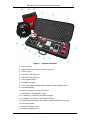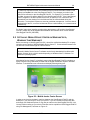
1
RST INSTRUMENTS LTD.
RST MEMS Digital Inclinometer
System Instruction Manual
Copyright ©2014 RST Instruments Ltd. All Rights Reserved.
RST Instruments Ltd.
11545 Kingston St.
Maple Ridge, B.C. Canada V2X 0Z5
Tel:
(604) 540-1100
Fax:
(604) 540-1005
Email: [email protected]
Website: www.rstinstruments.com
RST MEMS Digital Inclinometer Instruction Manual
i
RST MEMS Digital Inclinometer System
Although all efforts have been made to ensure the accuracy and completeness of the information
contained in this document, RST Instruments reserves the right to change the information at any time and
assumes no liability for its accuracy.
Product:
RST MEMS Digital Inclinometer System Instruction Manual
Document number:
Revision:
Date:
ICM0035S MEMS Digital Inclinometer System Instruction Manual.docx
S
March 11, 2014
RST Instruments
RST MEMS Digital Inclinometer Instruction Manual
ii
Table of Contents
1 GENERAL DESCRIPTION ..................................................................................... 10 2 DIGITAL PROBE .................................................................................................... 12 2.1 DUMMY PROBE .................................................................................................... 13 2.2 SIGN CONVENTION............................................................................................... 13 2.3 TAKING READINGS ............................................................................................... 15 3 INCLINOMETER CABLE AND REEL ..................................................................... 17 3.1 CHANGING THE BATTERY ...................................................................................... 17 3.2 WIRELESS COMMUNICATION ................................................................................. 18 4 ULTRA-RUGGED FIELD PC ......................................................................................... 18 4.1 OVERVIEW .......................................................................................................... 18 4.2 USING THE ULTRA-RUGGED FIELD PC................................................................... 19 4.2.1 MENU ITEMS .................................................................................................. 21 4.2.2 CREATING A SITE AND BOREHOLE ................................................................... 21 4.2.3 EDITING A BOREHOLE..................................................................................... 23 4.2.4 FILE SAVE FORMATS ...................................................................................... 25 4.2.5 STATUS SCREEN............................................................................................ 25 4.2.6 READINGS ..................................................................................................... 28 4.2.7 VIEW DATA .................................................................................................... 31 5 DOWNLOADING DATA TO A DESKTOP PC .................................................................... 35 5.1 INSTALLING MICROSOFT ACTIVESYNC™ ON WINDOWS XP ..................................... 35 5.2 SETTING UP MOBILE DEVICE CENTER ON WINDOWS VISTA, WINDOWS 7AND
WINDOWS 8 ................................................................................................................. 38 5.3 FILE MANAGEMENT .............................................................................................. 40 5.4 POST- PROCESSING THE DATA ............................................................................. 40 5.5 DATA AVERAGING ................................................................................................ 41 6 WHAT DOES THE DATA MEAN .................................................................................... 42 6.1 6.2 6.3 6.4 MEAN DEVIATION ................................................................................................. 42 ABSOLUTE POSITION ............................................................................................ 42 INCREMENTAL DISPLACEMENT .............................................................................. 42 CUMULATIVE DISPLACEMENT ................................................................................ 42 7 SYSTEM COMPATIBILITY ............................................................................................. 43 8 BACKING UP THE ULTRA-RUGGED FIELD PC INCLINOMETER DATA ............................... 44 8.1 MANUAL BACKUPS ............................................................................................... 44 9 RESTORING FILES ON THE ULTRA-RUGGED FIELD PC .................................................. 46 9.1 INSTALLATION THE RST DIGITAL INCLINOMETER PROGRAM ..................................... 46 9.2 RESTORING THE INCLINOMETER DATA FILES .......................................................... 46 10 CHARGING THE BATTERIES ..................................................................................... 47 10.1 10.2 ULTRA-RUGGED FIELD PC BATTERY .................................................................. 47 REEL BATTERIES .............................................................................................. 47 RST Instruments
RST MEMS Digital Inclinometer Instruction Manual
10.3 11 iii
BATTERY LIFE................................................................................................... 49 CARE AND MAINTENANCE ............................................................................... 50 11.1 11.2 11.3 11.4 11.5 11.6 PROBE & REEL CONNECTORS............................................................................ 50 INCLINOMETER PROBE ...................................................................................... 50 REEL AND CABLE .............................................................................................. 51 READOUT UNIT ................................................................................................. 51 CALIBRATION .................................................................................................... 51 STORAGE & BATTERY LIFE ................................................................................ 51 12 TROUBLESHOOTING ......................................................................................... 52 13 CONTACT US.......................................................................................................... 53 14 SENSOR SPECIFICATIONS ........................................................................................ 54 15 BLUETOOTH COMMUNICATION ................................................................................. 55 15.1 16 CHANGING THE REEL ........................................................................................ 57 IMPORTING AND EXPORTING FILES ........................................................................... 59 16.1 16.2 16.3 SAVING AND IMPORTING INCLINOMETER DATA INTO SLOPE INDICATOR SOFTWARE . 59 USING SLOPE INDICATOR DATA WITH INCLINALYSIS ............................................. 59 IMPORTING INCLINOMETER DATA INTO GTILT ...................................................... 60 RST Instruments
RST MEMS Digital Inclinometer Instruction Manual
iv
LIST OF FIGURES
Figure 1 – System Overview ....................................................................................................... 11 Figure 2 – Digital Probe Sizing ................................................................................................... 12 Figure 3 – Probe Orientation....................................................................................................... 14 Figure 4 – Sign Convention in the A-axis and deviation D measured by inclinometer probe ..... 14 Figure 5 – Probe Axes ................................................................................................................ 15 Figure 6 – Battery Removal / Installation .................................................................................... 17 Figure 7 – Ultra-Rugged Field PC ............................................................................................... 18 Figure 8 – Overview of Ultra-Rugged Field PC ........................................................................... 19 Figure 9 – RST Digital Inclinometer Software Main Menu .......................................................... 20 Figure 10 – Creating a Site and Borehole ................................................................................... 21 Figure 11 – Create Site ............................................................................................................... 22 Figure 12 – Edit Borehole Screen ............................................................................................... 23 Figure 13 – Data Filename Screen ............................................................................................. 24 Figure 14 – Status Screen .......................................................................................................... 25 Figure 15 – Calibration Screen ................................................................................................... 26 Figure 16 – Bluetooth Status Screen .......................................................................................... 27 Figure 17 – Field PC Status Screen ........................................................................................... 27 Figure 18 – Readings Screen ..................................................................................................... 28 Figure 19 – Readings Options Screen ........................................................................................ 29 Figure 20 – Advanced Options Menu ......................................................................................... 30 Figure 21 – View Data Screen .................................................................................................... 31 Figure 22 – Graphing Files ......................................................................................................... 32 Figure 23 – Viewing Files ............................................................................................................ 33 Figure 24 – Save As… Option .................................................................................................... 34 Figure 25 – ActiveSync Connection Screen ............................................................................... 35 Figure 26 – Setting Up a Partnership .......................................................................................... 36 Figure 27 – Synchronization Settings ......................................................................................... 37 Figure 28 – ActiveSync Screen ................................................................................................... 37 Figure 29 – Mobile device Center Screen ................................................................................... 38 Figure 30 – Synchronization Settings on Windows Vista™, Windows™ 7 and 8 ....................... 39 Figure 31 – Accessing Files on Windows Vista™, Windows™ 7 and 8 ..................................... 39 Figure 32 – File Structure ........................................................................................................... 40 Figure 33 – Sample Data File ..................................................................................................... 41 Figure 34 – File Backup .............................................................................................................. 44 Figure 35 – File Backup Options ................................................................................................. 45 Figure 36 – Standby Mode .......................................................................................................... 47 Figure 37 – Initial Charge ............................................................................................................ 48 Figure 38 – MED Charge ............................................................................................................ 48 Figure 39 – HI Charge ................................................................................................................ 48 Figure 40 – MAX Charge ............................................................................................................ 48 Figure 41 – Error in Charging ..................................................................................................... 48 Figure 42 – Field PC Wireless Icon ............................................................................................ 55 Figure 43 – Field PC Wireless Main Menu ................................................................................. 56 Figure 44 – Bluetooth Options .................................................................................................... 56 Figure 45 – Inclinometer Connection List ................................................................................... 57 Figure 46 – Inclinometer Reel/Bluetooth Properties ................................................................... 58 RST Instruments
RST MEMS Digital Inclinometer Instruction Manual
10
1 GENERAL DESCRIPTION
The RST MEMS Digital Inclinometer System represents a breakthrough in inclinometer
system technology, providing unprecedented accuracy, efficiency and ease of use. The
system is comprised of a Digital Inclinometer Probe, Cable system, Reel with battery power,
and an Ultra-Rugged Field PC running Mobile Microsoft Windows™ that functions as a
readout, analysis, and data storage device.
Wireless communication between the inclinometer control reel and the Ultra-Rugged Field
PC ensures ease of use and reliability, by removing two weaknesses inherent in
conventional analog inclinometer systems. By removing the physical connection between
the inclinometer control cable and the readout instrument there is no concern with fragile
connectors, cable related failure and related reliability problems. The Achilles heel of any
inclinometer control cable reel is the slip ring required to maintain electrical contact as the
reel revolves. As the RST system is wireless from the control cable to the readout, a slip
ring is not required, and there are no associated electrical continuity problems.
The RST digital inclinometer probe incorporates cutting edge MEMS (Micro Electro
Mechanical Systems) technology providing high precision and durability. A highly accurate
survey of the inclinometer casing is used to establish the initial position of the casing. Any
subsequent deviations in the casing from this initial value (i.e. baseline reading) represent
changes occurring in the subsurface. The RST MEMS Digital Inclinometer System can
accurately measure the rate, depth and magnitude of these deviations.
The information included in this manual outlines the use and care of the RST MEMS Digital
Inclinometer System. It provides examples of how to take readings and interpret the data.
For more information on the installation of inclinometer casing, and other related issues,
please contact RST Instruments Ltd.
Note
Proper care and maintenance of the MEMS Digital Inclinometer System will greatly extent
the life of the instrument and accuracy of the readings. Please take the time to read this
manual thoroughly. If any questions arise, do not hesitate to contact RST Instruments Ltd.
Contact information is given in section 13. Proper maintenance of the probe after each
use is outlined in section 11.
X
X
X
X
Functions:
•
Measure lateral movement of earthworks or structures
•
Landslides
•
Embankment fills
•
Stability adjacent to excavations or underground workings
•
Deflection of piles, piers, abutments or retaining walls
RST Instruments
RST MEMS Digital Inclinometer Instruction Manual
Figure 1 – System Overview
1. Soft Shell Case
2. Digital Inclinometer Probe (w/ protective end cap)
3. Field PC stylus
4. 70mm/2.75” OD Cable Grip
5. 85mm/3.34” OD Cable Grip
6. Ultra-Rugged Field PC
7. Reel Battery Charger
8. 12V DC car adapter for Reel Battery Charger or Ultra-Rugged Field PC
9. Spare Reel Battery
10. Silicone Lubricant (for use on connectors)
11. USB Cable for Ultra-Rugged Field PC
12. AC Adapter (110-240V) for Reel Battery Charger
13. AC Adapter (110-240V) for Ultra-Rugged Field PC
14. Cable Reel with Wireless Communication System and protective end cap
15. Reel Carrying Case
16. Micro-fiber cleaning Cloth
17. Software Installation DVD
RST Instruments
11
RST MEMS Digital Inclinometer Instruction Manual
12
2 DIGITAL PROBE
In general terms, the new Digital Probe resembles that of the traditional analog probes sold
by RST. The RST Digital Inclinometer has the smallest package available for a given wheel
spacing, with the best ability to track deformed casings. This means that the Digital Probe
can handle greater bends in the casing without fouling. The RST metric probe can negotiate
a radius of 1.88m (74”) in 70mm (2.75”) OD inclinometer casing. The RST Digital
Inclinometer will thus continue to provide readings past the limit for other probes on the
market (see Figure 2).
X
X
Figure 2 – Digital Probe Sizing
The connectors, wheels, and wheel carriages are the most precise and durable in the
industry. The probe wheels are made of high grade hardened and heat-treated stainless
steel. These are extremely durable and the most robust on the market.
The digital probe also incorporates shear pins on the wheel assemblies. In the event that
the probe gets stuck in the inclinometer casing, a force of approximately 300 lbs is required
to shear the shear pin. No damage to the probe or cable will result. Please contact RST
Instruments Ltd. for further instructions on the replacement of shear pins.
RST Instruments
RST MEMS Digital Inclinometer Instruction Manual
13
2.1 DUMMY PROBE
RST can supply a “dummy” inclinometer probe for testing purposes in a borehole. RST
encourages customers to try the new digital dummy probe in existing holes where the
competitor’s probes do not work. If it is found that the dummy probe passes through all
areas of the casing, the RST MEMS Digital Inclinometer System will function. Therefore the
existing hole will still be viable and a new hole will not need to be drilled.
The RST dummy probe has the exact same weight and dimensions as the standard probe.
A ring is provided in place of the connector which allows the dummy probe to be lowered by
a rope. For further information on obtaining an RST Dummy Probe, please contact RST
Instruments Ltd (Section 13).
X
X
2.2 SIGN CONVENTION
The Digital Inclinometer Probe houses two MEMS accelerometers, which measure tilt in two
axes. Proper installation of the inclinometer casing attempts to align one set of grooves in
line with the axis of expected movement. This is called the A axis. The perpendicular set of
grooves is the B axis.
When an inclinometer casing is surveyed for the first time (i.e. baseline readings), it is
necessary to select a fixed direction reference for the probe so that each time a survey is
repeated, the probe will always have the same orientation in the casing.
For example, in an area suspected of landslide activity, the first set of readings would be
taken by placing the upper wheels of the probe in the casing groove closest aligned to the
downslope direction. Figure 3 illustrates an inclinometer casing installed with a groove
orientation in the general downslope direction.
X
X
In practice, it is often difficult to achieve exact orientation of grooves relative to some
predetermined direction. The groove closest to the anticipated movement direction is usually
chosen as the main reference direction. It is recommended that this direction (A+) be
marked on the casing itself to ensure surveys are performed in the same manner each time.
The azimuth of this groove direction can be measured in a clockwise direction from the main
reference direction (A+). All subsequent measured inclinometer movements would be
referred to this direction.
Readings taken from the inclinometer probe (see Section 4.2.6) are actually deviations from
the vertical over the distance between the upper and lower wheels (see Figure 4), calculated
as:
D = L × sine( α )
Where:
L = inclinometer probe length (typically 0.5m for a metric probe or 2 ft for an
imperial probe, as defined in Section 0)
α = inclination angle of probe from vertical axis
RST Instruments
RST MEMS Digital Inclinometer Instruction Manual
14
Figure 3 – Probe Orientation
The RST Digital Inclinometer System uses the industry standard sign convention, where tilt
in the direction of the upper wheels results in a positive deviation and tilt in the direction of
the lower wheels results in a negative deviation (Figure 4).
X
X
Figure 4 – Sign Convention in the A-axis and deviation D measured by
inclinometer probe
RST Instruments
RST MEMS Digital Inclinometer Instruction Manual
15
Figure 5 shows the sign convention for the A and B axis.
X
X
B-
B+
UPPER WHEEL
BEHIND PROBE
A-
A+
UPPER
WHEEL
Figure 5 – Probe Axes
2.3 TAKING READINGS
1. Upon arrival at the site, remove the protective caps from the casing, the probe and
the control cable. Attach the probe to the reel by aligning the keyways and
threading the connector onto the probe. Take care to only turn the threaded ring,
not the cable itself. Do not over tighten the connector, make it hand tight.
2. Handle the inclinometer probe very carefully as the accelerometers are very
susceptible to shock.
3. Once connected, turn on the power to the reel. This energizes the MEMS
accelerometers and makes them less susceptible to shock.
4. Insert the probe into the borehole aligning the upper wheel in the direction of the A+
axis (see section 2.2).
X
X
5. Lower the probe to the desired depth slowly and as smoothly as possible. Be
extremely careful not to bounce the probe off the bottom of the hole.
6. Once the desired location has been reached (i.e. base of the borehole), place the
cable grip on the top of the casing and hang the cable by the aluminum crimps. The
objective is placement repeatability within 5mm (0.25 inch). This is extremely
important to ensure accurate and repeatable results.
7. Always pull the probe upwards to the desired location. If you accidentally pull the
probe too far, lower the probe back down to the previous depth, and then pull it back
to the intended depth. This procedure ensures that the readings will remain
consistent.
Warning
Do not drop the cable marks onto the cable grip. The cable has very little stretch,
especially near the top of hole, and the impact on the cable marks may “hammer”
them out of position or break the cable. This effect has been demonstrated for
drops as little at 70 mm
RST Instruments
RST MEMS Digital Inclinometer Instruction Manual
16
8. At each location allow the readings to stabilize. Reading stability can be gauged by
both the noise bar and the standard deviation which are displayed on the Readings
Screen (sections 4.2.6).
X
X
9. Once the readings have stabilized, press the Accept button and move the probe to
the next interval as prompted by the software.
10. Continue logging the borehole until the top is reached, the software will then prompt
you to turn the probe 180 degrees and repeat the survey, this time with the lower
probe wheels in the A+ groove.
Warning
When the probe has reached the top of the casing, avoid allowing the wheel
assemblies to snap out of the casing. As the wheels reach the top, grasp them
with your hand and release the wheel assembly slowly until it reaches its stops.
Failure to do so will damage the stops and subject the MEMS accelerometers to
sudden shock which can damage them and affect the calibration of the probe.
11. Prior to lowering the probe for the second pass, remove the cable grip to avoid
accidentally catching the marks on the cable grip, which would otherwise impact
load the marks, cable, and probe. Once the probe is at the bottom of the hole,
replace the cable grip and position the probe for the deepest reading.
12. During the second pass, checksum data will be displayed underneath each reading.
Ensure that these remain small and consistent; however checksums can vary due to
different site conditions. Large checksums can indicate errors in probe positioning
or fouling of the probe. Expect checksums to be slightly larger when the probe
encounters an expansion coupling in the casing (if applicable).
13. The RST MEMS Digital Inclinometer has the ability to perform data reduction in the
field, please refer to section 4.2.7 for information on viewing and validating the data.
X
X
14. Upon completion of the survey, close the inclinometer program, turn off the power to
the reel, and disconnect the probe. Wipe off the probe and cable. Replace endcaps on the cable and probe. Replace the protective cap on the casing.
15. Upon returning to the office, clean the instrument and reel once more to remove any
moisture from the instruments and the case. Remove and recharge the batteries for
the Reel and connect the power and USB communication cables to the UltraRugged Field PC (Figure 7). Please refer to section 11 for proper care and
maintenance of the system.
X
X
X
X
16. Transfer data to a desktop PC using Microsoft ActiveSync™ or Microsoft Mobile
Device Center software (section 5).
RST Instruments
RST MEMS Digital Inclinometer Instruction Manual
17
3 INCLINOMETER CABLE AND REEL
The RST MEMS Digital Inclinometer System comes with a durable lightweight reel that is
easy to handle. Since only a pair of conductors is needed in the cable, the weight and
dimensions of the cable are drastically reduced as compared to a traditional analog cable.
The reel is battery powered and houses the electronics used for wireless communication.
An important part to any inclinometer casing survey is the repeatability of the depth
measurements. It is extremely important that measurements be consistently within 5mm
(0.25in) of one another between subsequent surveys. To facilitate accurate repeatability,
two aluminum seats are provided with the system, for 70mm (2.75”) and 85mm (3.34”) OD
casing respectively. The seats provide a solid reference for the cable crimps to sit in. The
result is that operator error is reduced, checksums will be smaller and surveys more
accurate.
The thin, strong cable contains a Kevlar® strength member, allowing a long length of cable
to fit on a small reel with no stretch. The aluminum sleeved measure marks are precision
swaged to the cable and are not subject to tearing when handling. The measure marks are
spaced at 0.5 metre or 2 feet intervals. The cable is marked with a red measure mark and a
label every 5 metres or 10 feet depending on whether the metric or imperial system is being
used. The urethane jacket is highly abrasion resistant, and maintains flexibility at low
temperatures. It is good practice to avoid running the cable over sharp edges and to
periodically clean it with a clean soft cloth. Be sure to keep the protective cap on the
connector whenever the probe is not in use and avoid dropping or banging the cable end.
Always keep the connectors and threads clean by rinsing them with water. Exercise care
when connecting and removing the cable from the probe. Make sure to only turn the
connector ring, not the entire cable.
3.1 CHANGING THE BATTERY
The reel uses a 7.4V lithium-ion camcorder battery. The system comes with two batteries
and a charger. Adapters are supplied to allow the charger to function in a vehicle (12V DC),
or 110-240V AC power (see Figure 1). To remove the battery, simply unscrew the cap off
the reel hub by turning it counter-clockwise (Figure 6). Upon replacement of the battery,
ensure to align the battery contacts with the contacts in the Reel hub to allow proper
operation. For more information on charging and care of the batteries please see
section 10.2.
X
X
X
X
X
X
Figure 6 – Battery Removal / Installation
RST Instruments
RST MEMS Digital Inclinometer Instruction Manual
18
3.2 WIRELESS COMMUNICATION
Turn on the power to the reel by pressing the button located under the battery housing on
the Reel Hub (Figure 6). A solid light indicates the reel has been powered on. After turning
on the power to the reel, it automatically searches for a connection to the Ultra-Rugged Field
PC. Once the Ultra-Rugged Field PC is powered up, and the RST Digital Inclinometer
software is launched, it will automatically try and link to the reel. The light indicator will flash
rapidly when the reel is communicating with the probe. During Ultra-Rugged Field PC
wireless communication, the reel indicator light will blink with 1 second intervals. The status
of the connection is also displayed on the status screen or on the bottom of the main menu
screen (see section 4.2.5).
X
X
X
X
Note
The reel incorporates power saving feature. After 5 minutes of inactivity and lack of UltraRugged Field PC wireless communication, the reel will power down automatically to save
battery charge.
4 ULTRA-RUGGED FIELD PC
The RST MEMS Digital Inclinometer System comes with an Ultra-Rugged Field PC running
Microsoft Mobile Windows™, which is the heart of the system. This hand-held device
functions as a readout and data storage device. Data reduction can be performed “at-theborehole” as soon as the survey is complete. The program has the ability to create plots of
the data instantly. This is important if on-site personnel require immediate results to verify
that data is accurate. No time is wasted by having to take the readout back to the office to
download and process the data.
4.1 OVERVIEW
The Ultra-Rugged Field PC is well suited for use in the often demanding field conditions.
Figure 7 – Ultra-Rugged Field PC
RST Instruments
RST MEMS Digital Inclinometer Instruction Manual
19
4.2 USING THE ULTRA-RUGGED FIELD PC
Once the inclinometer probe is connected to the reel and the probe is ready to be placed in
the borehole, turn on the power to the Ultra-Rugged Field PC by pressing the power button
(Figure 8).
X
X
Figure 8 – Overview of Ultra-Rugged Field PC
Front Image
1. Elastomer overmold
9. Microphone
2. Touchscreen
10. Keypad buttons
3. Buttons Control
11. LED Indicator
4. Hold-to-Zoom
12. Power button
5. Pictures and Videos
13. Enter button
6. Tab button
14. Backspace
7. Home Screen
15. Context Menu Button
8. Shift Function
16. Right Soft Key
RST Instruments
Back Image
17. Speaker
18. Battery Door
19. Hand Strap
20. Stylus
21. Stylus Tether
RST MEMS Digital Inclinometer Instruction Manual
20
Bottom Image
22. USB client (micro USB)
23. Microphone/Headphones jack
24. 12V DC jack
25. USB host (full size USB)
26. 9-pin serial port
Note
DC charging is done through the 12V DC jack (barrel connector, bottom left of the unit).
Once the power is turned on, use the stylus to navigate through the operating environment.
If you are unfamiliar with the Microsoft Mobile Windows™ operating environment, please
refer to the “Getting Started Guide” which is supplied on CD-ROM with the Ultra-Rugged
Field PC. From the Start menu, choose: Digital Inclinometer to launch the Digital
Inclinometer Software. A screen similar to the following will appear:
Figure 9 – RST Digital Inclinometer Software Main Menu
Upon start-up, the inclinometer will automatically begin searching for the Reel and
Inclinometer Probe. This status is displayed at the bottom of the screen.
The opening screen (Figure 9) displays the current set-up and status of the system. The top
menu provides a list of the current boreholes (a default site/borehole will appear, if none
have been created). Underneath the borehole list is a drop-down dialog which is used to
choose the site.
X
X
The centre portion of the screen shows the site, borehole, depth, interval and units that are
currently set. In this example we are using a default site and a default borehole. The depth
of the borehole is 10 metres, measurement interval is 0.5 metres and the deflection units are
in millimetres.
RST Instruments
RST MEMS Digital Inclinometer Instruction Manual
21
4.2.1 MENU ITEMS
The File menu allows the user to backup the current files to the Field PC non-volatile
memory location and also Exits the Digital Inclinometer program. For more information on
the backup function please refer to section 8.
X
X
The Connections menu allows the user to view the status of the Bluetooth (radio) connection
and allows the user to disconnect and reconnect to the reel and probe manually. Should a
new Reel be used (i.e. a replacement which was not supplied with the original system), the
Ultra-Rugged Field PC needs to be made aware of this new instrument, and thus the
Bluetooth Connections must be changed. For further information please refer to
section 15.1.
X
X
4.2.2 CREATING A SITE AND BOREHOLE
To create a new borehole and site, click on the “Create Borehole” button on the Main Menu
and the following screen will appear:
Figure 10 – Creating a Site and Borehole
First, create a new site by pressing the Create button under the Site List heading. This
brings up the following screen:
RST Instruments
RST MEMS Digital Inclinometer Instruction Manual
22
Figure 11 – Create Site
Please note that the remote keyboard automatically pops up when this screen is selected.
Touching the keyboard icon in the bottom of the screen can hide the keyboard. Press New
Site… and enter the new site name and borehole name in the appropriate dialog boxes.
Once the new site and borehole is entered, press OK. Both site name and borehole names
can be edited, deleted, re-named and moved by pressing the appropriate options on this
screen. To return to the main menu, press the Close button at the bottom of the screen
(after hiding the remote keyboard), or press OK at the top right of the screen.
RST Instruments
RST MEMS Digital Inclinometer Instruction Manual
23
4.2.3 EDITING A BOREHOLE
Pressing the Edit Borehole button on the main menu screen invokes the following screen:
Figure 12 – Edit Borehole Screen
The site and borehole name appear at the top of the screen (in this case they are “default”)
followed by depth, interval, units and reading units. Set depth to the depth of the borehole of
the lowest reading you wish to take (match this to the cable marking). Choose the interval
and units based on whether you are using a metric or imperial probe. In most cases this will
be either 0.5 metres or 2 feet, which is equal to both the length of the probe and the divisions
marked on the inclinometer cable.
The Horizontal Borehole checkbox should be used only when connecting horizontal probe.
For all other probes, the Horizontal Borehole checkbox should be cleared.
Pressing the Comment button invokes a screen where comments can be made about the
site, borehole information etc. Comments are entered using the remote keyboard.
Pressing the Data Filename button brings up the following screen:
RST Instruments
RST MEMS Digital Inclinometer Instruction Manual
24
Figure 13 – Data Filename Screen
Filename Type can be chosen by the drop-down menu. Options under this menu include
User Selected, Borehole, Site and Site Borehole. These options specify the name of the file
to be written after the borehole is surveyed. If User Selected is chosen, enter the name in
the dialog box under User Selected Filename. The Filename Sequence Number defines the
numeric label of the file name. All subsequent files will be named in sequence. For
instance, if you had a User Selected File named “Test”, subsequent files will be named:
Test(2), Test(3), etc. (incremented by 1).
Note
The default filename for an inclinometer survey is the Borehole name. If User Selected is
chosen as the file format, and the User Selected Filename dialog box (Figure 13) is left
blank, the software will default to the Borehole name. In most cases, it is recommended
that the data files be managed using the Borehole name, as this will avoid confusion
between multiple sets of data under a single Site.
X
RST Instruments
X
RST MEMS Digital Inclinometer Instruction Manual
25
4.2.4 FILE SAVE FORMATS
File Save Format enables the user to choose which format to save the inclinometer file in.
To change the file save format choose the appropriate option from the drop-down list as
shown in Figure 13. These are outlined below:
X
X
1. Digital Inclinometer (*.csv) format: Files are saved in a format which includes the
probe serial number in the header file.
2. Standard RST(*.csv) format: This is the default file setting and is compatible with
RST Inclinalysis™ software. Files are saved as *.csv (comma separated value).
This data format also has the ability to be imported into most popular spreadsheet
software. Files of this type can also be imported into GTilt (section 16.3).
X
X
3. RPP Format (*.rpp): This type of file can be imported into Inclinalysis™ and is also
compatible with Slope Indicator’s software including DMM for Windows and DigiPro.
GTilt and GTilt Plus software also has the ability to import *.rpp file formats. If
directly comparing data between two inclinometer systems, please ensure that the
depth placement of the probe is identical between the surveys with the two different
systems (section 7). For further reference on importing *.rpp files into Slope
Indicator’s software, please see section 16.1.
X
X
X
X
4. Standard RST (*.dty): File format designed to be imported directly into GTilt and
GTilt Plus software. Please note however, that the other file types listed above can
also be imported into GTilt.
Once the correct data file options have been chosen, exit the Reading Data File Options
screen by pressing OK. If you want to exit without saving the changes, press Cancel. You
will be returned to the Edit Borehole screen. If all the parameters in the Edit Borehole
screen are correct press OK, else press Cancel and you will be returned to the Main Menu.
The new borehole information will be displayed in the bottom half of the Main Menu screen.
Verify that these settings are correct.
4.2.5 STATUS SCREEN
Navigate to the Status Screen by pressing the Status button on the main menu. The
following screen will appear:
Figure 14 – Status Screen
RST Instruments
RST MEMS Digital Inclinometer Instruction Manual
26
If the Ultra-Rugged Field PC is connected to the Reel and the Probe, information will appear
in the appropriate areas. If there is no connection the information fields will be blank (and
the status will read not connected). Vital information for both the Reel and the Probe is
displayed which includes: Battery Voltage, Serial Number, Model Label, Firmware Version,
Run Time and Status.
Choosing the Calibration tab invokes the following screen:
Figure 15 – Calibration Screen
The Calibration Screen provides information about the calibration date, calibration version,
probe length and probe units (metric or imperial). Corrections can also be made to individual
inclinometer probes to account for latitude and elevation changes.
Note
RST highly recommends that the inclinometer probe be calibrated on an annual basis. The
probe should also be recalibrated if it has been exposed to any type of shock or shows
high checksum values for no apparent reason.
RST Instruments
RST MEMS Digital Inclinometer Instruction Manual
27
Clicking on the Bluetooth tab brings up the following screen:
Figure 16 – Bluetooth Status Screen
The Bluetooth Status screen indicates which device is connected and the status of the
connection. Please note that the range of the Bluetooth radio is approximately 10 metres
and this distance may vary depending on objects and line of site.
The above two screens are used primarily to confirm that the Ultra-Rugged Field PC has
established wireless communication with the Reel and Digital Probe and to display the
hardware information. If communication has not been established, the hardware information
will not display until a satisfactory connection has been made.
Pressing the Field PC tab brings up specific information about the Ultra-Rugged Field PC
serial # as shown in the following screen:
Figure 17 – Field PC Status Screen
RST Instruments
RST MEMS Digital Inclinometer Instruction Manual
28
4.2.6 READINGS
Once you have set up the Site Name, Borehole Name, Filename and the Ultra-Rugged Field
PC has successfully connected to the Reel and Digital Probe (see Status Screen) you are
ready to begin logging the borehole. This menu is only accessible once the readout is
connected to both the Reel and the Digital Probe. From the Main Menu, pressing the
Readings button invokes the following screen:
Figure 18 – Readings Screen
After a few seconds the real-time reading should appear as in Figure 18. This screen shows
the real-time data in both the A and B axes. The units are displayed underneath both sets of
readings. To the left of the readings is a dynamic bar which indicates the noise level (i.e. the
difference, reported in microVolts, between subsequent readings). The user should wait
until the noise level is at a minimum before taking a reading. This minimum can vary
depending on the site conditions. In particularly noisy environments (i.e. heavy equipment is
moving in the vicinity) the amount of averaging can be adjusted to help reduce the noise (for
more info. please refer to the Averaging Data section in this manual, section 5.4 and Figure
19). The number displayed under the noise bar reports the microVolt change between
successive readings. It should simply be used as a reference as to how noisy the readings
are, this number does not correlate directly to the measurement units, it simply indicates the
microVolt change between each subsequent measurement (1 measurement per 0.4
second).
X
X
X
X
X
X
The current depth of the instrument in this example is set to 10.0 metres. Pressing the
Accept button will store the reading and the depth will move to whatever the next interval is
set at (i.e. 9.5m). The arrow keys allow the user to scroll up and down the readings which
permits re-taking readings if necessary.
Note
Be careful not to miss any data intervals when using the scroll feature as this can offset the
data. At any time the user is able to view the data by pressing the View Data button to
confirm that they have the probe in the correct location and the readings at that depth have
been taken correctly.
RST Instruments
RST MEMS Digital Inclinometer Instruction Manual
29
The small black dot on the right hand side of the screen appears whenever data is being
sent from the probe.
Once the top of the hole has been reached, the software will prompt the user to turn the
probe 180o and lower it back to the bottom of the hole (unless the user specifically sets the
software to only take a single set of readings, please see the Advanced Options
Menu, Figure 20). The readings will automatically start at 50.0 metres once again (in this
example). Check-Sum data will appear in a smaller font underneath the current readings.
The real-time check-sums allow the user to monitor the second set of readings. If the checksum is large or inconsistent, either the probe has fouled or the probe is not at the correct
measurement depth. Continue logging until the top of the hole is reached. If the probe has
been accidentally raised above the measurement point, lower the probe back down below
the proper depth and then raise it slowly to the correct depth. This ensures consistent and
accurate readings. Once the top is reached on the second pass, a dialog box will appear
that says “Readings Complete”. The software will then save the data to the filename which
was specified in the Reading Data File Options screen (see section 4.2.3).
X
X
X
X
Pressing the Options button on the readings screen brings up the Readings Options screen:
Figure 19 – Readings Options Screen
This option allows the user to specify whether or not the data from the probe is to be
averaged. The number of readings to be averaged can be set in Average Number dialog
box.
Note
Readings from the probe are taken once 0.4 second, therefore increasing the amount of
averaging means that you increase the wait time between taking readings (i.e. if an
averaging value of 5 is chosen, you must wait at least 2 seconds after moving the probe
before taking a reading).
The number of decimals shown can be changed in the Display Digits dialog box. Pressing
the Comment button permits the user to make any comments about the data set and the
Data Filename allows the user to change the name of the data file the information is written
RST Instruments
RST MEMS Digital Inclinometer Instruction Manual
30
to upon completion of logging the borehole (for additional information please see
section 4.2.3).
X
X
When the incline capable probe is connected, the Probe Mode settings allow switching
between vertical mode and incline mode. The Probe Mode settings do not appear for single
mode probes.
Pressing the Advanced button brings up the following screen:
Figure 20 – Advanced Options Menu
The first check box allows the user to specify whether or not to take a single set of readings
during a borehole survey. The inclinometer readout will save the data after a single pass of
the borehole. A sound option allows the user to turn on/off the sound upon acceptance of a
reading. User specified sound files (*.wav) can be placed in the following directory:
My Device\My Documents\Digital Inclinometer\SoundFiles\
This allows the user the option to have a custom sound played each time a reading is taken.
The default sound is a simple beep.
The Noise Bar can be turned on and off and the drop-down menu provides a choice for the
limit of the range of the Noise Bar. The numbers represent microVolt reading from the
inclinometer probe. The last pull-down menu allows the option to display the standard
deviation of the incoming data. This range can also be adjusted, depending on how noisy
the readings are in the field. Measurements should be taken at the point of least noise
whenever possible to obtain the most accurate readings.
RST Instruments
RST MEMS Digital Inclinometer Instruction Manual
31
4.2.7 VIEW DATA
By pressing the View Data button from the main menu, the following screen appears:
Figure 21 – View Data Screen
All borehole data files associated with the particular borehole that has been selected (from
the Main Menu) will appear in the top dialog box. The detailed file information appears on
the lower half of the screen and this includes: site, borehole, depth/interval, reading units,
reading date and file type. Filenames can be sorted by date, type or name by selecting the
appropriate option in the drop-down box.
In order to display the data, the appropriate files must be chosen from the list. To select a
file, first highlight the file in the top dialog box and then press the Select button. If the file
has been selected, an “S” will appear to the left of that file. To choose a base file, highlight
the appropriate file and press the Base button. A “B “ will appear to the left of the file name
confirming that this file is now the base file. Note that the Base file and the Selected files
can be changed at any time by highlighting the file and pressing the Base or Select buttons.
The software only allows the user to have a single Base File. To unselect any file, simply
highlight that particular file and press either select or base a second time and the B or S to
the left of the file will subsequently disappear.
The base file represents the original survey of the inclinometer hole, from which all other
measurements are compared. Typically, a base file is chosen and kept the same throughout
the life of the inclinometer hole in order to quantify any lateral displacements which occur.
Once the appropriate files are chosen, the user can choose to display the data in tabular
format by pressing the View Files button, or in graphical format by pressing the Graph Files
button.
RST Instruments
RST MEMS Digital Inclinometer Instruction Manual
32
Pressing the Graph Files button will bring up the following screen:
Figure 22 – Graphing Files
Several tools are available in the bottom pull-down menus to allow manipulation of the
graph. The left-hand pull down allows the user to choose how the data is displayed, with
Mean, Absolute, Cumulative or Checksum options. The centre menu allows the user to
choose between plotting either the A or B axis. The third menu Options, allows the user to
manipulate the cursor, zoom, pan, change the scale, move the legend, or change the
appearance of the graph. Three icons also appear in the bottom left of the screen which
allow further manipulation of the graph. These are self-explanatory and the user is
encouraged to explore these options if required. The default setting for all plots is autoscale. To exit the graphical display, hit the OK button in the top right corner of the screen.
Pressing the View Files button invokes the following screen:
RST Instruments
RST MEMS Digital Inclinometer Instruction Manual
33
Figure 23 – Viewing Files
The top left pull-down menu allows the user to change the type of data that is reported in the
table. The options include: Raw Data A, Raw Data B, Checksum, Mean, Absolute and
Cumulative. The top right pull-down menu is used to choose which of the selected data files
is currently being displayed. Please note that the base data file will contain the prefix “B:” so
that it can be easily identified.
The bottom portion of the screen has three menus which allow the user to display the data in
either decimal or scientific notation, change the number of decimal places displayed, and a
graph button which takes you to the graph data screen. At any time you may exit from this
screen by pressing OK in the top right corner of the screen.
Pressing the Save As button invokes the following screen:
RST Instruments
RST MEMS Digital Inclinometer Instruction Manual
34
Figure 24 – Save As… Option
This function allows the user to edit the filename, file type and the measurement units. For
more on file formats please refer to section 4.2.4.
X
X
RST Instruments
RST MEMS Digital Inclinometer Instruction Manual
35
5 DOWNLOADING DATA TO A DESKTOP PC
The software used to transfer data will depend on the version of Microsoft Windows installed
on a desktop PC.
For Windows XP versions, ActiveSync™ is required. Windows Vista has a build-in Mobile
Device Center. It is highly recommended to download and install the newest updates from
Microsoft website.
5.1 INSTALLING MICROSOFT ACTIVESYNC™ ON WINDOWS XP
In order to communicate between the Ultra-Rugged Field PC and a desktop PC or laptop,
Microsoft’s ActiveSync™ software is required and is included with the Digital Inclinometer
System. Communication between the two devices is achieved through an USB connection.
Note
Microsoft’s ActiveSync™ software can be freely downloaded from Microsoft’s website.
Important
Don’t connect the USB cable before installing ActiveSync™ software. Doing so will result in
installation of generic Windows USB drivers which will not work with Ultra-Rugged Field
PC.
To install Microsoft ActiveSync™:
1. Insert the Ultra-Rugged Field PC Companion CD into the CD-ROM drive. On most
systems, Windows will automatically launch the setup program. Minimum system
requirements are outlined in the jacket of the CD-ROM. Once the CD is up and
running, a graphical window will open. Press the play icon on this window.
2. Click the link marked Start Here.
3. Click Install ActiveSync. Note: When prompted to download the file, select Run this
program from its current location. Installing Microsoft Outlook is not necessary, for
the Digital Inclinometer System to function. If you wish to use the Ultra-Rugged
Field PC for e-mail, install Outlook.
4. Follow the on-screen instructions until you reach the screen shown below, and then
continue with Step 5.
.
Figure 25 – ActiveSync Connection Screen
5. Click Finish button.
RST Instruments
RST MEMS Digital Inclinometer Instruction Manual
36
6. Insert the AC Adapter plug into an electrical outlet (item 13, Figure 1). Connect the
AC connector barrel connection on the base of the Ultra-Rugged Field PC (Figure
7) .
X
X
X
X
7. If you have not already done so, connect the micro USB connector to the connector
on the base of the rugged case and the USB connector to the USB port on either the
front or back of your personal computer.
Note
ActiveSync will automatically detect the Ultra-Rugged Field PC connection.
8. Continue to follow the ActiveSync instructions to establish a partnership. Eventually
you will come to a screen like the one below:
Figure 26 – Setting Up a Partnership
In order to synchronize the data in real-time between the Ultra-Rugged Field PC and the
desktop PC, you must set up a sync partnership. If you do not wish to synchronize data and
simply use Windows Explorer to copy files to and from the Ultra-Rugged Field PC, click
Cancel to leave the connection as Guest Partnership and skip the remaining instructions.
1. To set up a sync partnership, press Next.
2. Uncheck the option for synchronizing with Microsoft Exchange Server, press Next.
3. Decide what type of information you would like synchronized with the desktop
computer. If you are only using the Ultra-Rugged Field PC for the purposes of
transferring Digital Inclinometer information, uncheck all the options and place a
check mark next to the Files Folder (see below).
RST Instruments
RST MEMS Digital Inclinometer Instruction Manual
37
Figure 27 – Synchronization Settings
The software will notify you that it will create a folder on the desktop which links directly to
the Ultra-Rugged Field PC (press OK). Click Next, and then Next on following dialog, then
Finish the installation. Once the partnership is established, the PC will recognize and
automatically synchronize to the Ultra-Rugged Field PC each time it is connected with the
USB cable.
Figure 28 – ActiveSync Screen
RST Instruments
RST MEMS Digital Inclinometer Instruction Manual
38
Important
It is extremely important that the user realizes that the synchronized folder created on the
desktop is an active link to the Ultra-Rugged Field PC. Any changes you make in that
folder will be reflected on the Ultra-Rugged Field PC. For example, if you delete a file in
the folder, the same file will be deleted on the Ultra-Rugged Field PC. If the Ultra-Rugged
Field PC happens to be disconnected at the time, as soon as it is re-connected it will
automatically see the missing file in the folder and the file will be deleted during the
connection. It is therefore important to exercise good data management. Once the data is
synchronized to the PC, move the inclinometer files to a safe location (i.e. a network server
or hard drive).
For further instructions regarding synchronizing data between a PC and the Ultra-Rugged
Field PC, please refer to the supplied documentation and software which comes with the
Ultra-Rugged Field PC (CD-ROM).
5.2 SETTING UP MOBILE DEVICE CENTER ON WINDOWS VISTA,
WINDOWS 7AND WINDOWS 8
Before connecting to Ultra-Rugged Field PC, it should be verified that desktop PC or laptop
contains current version of Microsoft Mobile Device Center™. Communication between the
two devices is achieved through an USB connection.
Note
Microsoft’s Mobile Device Center™ software can be freely downloaded from Microsoft’s
website. Choose 32 bit or 64 bit version depending on Windows Vista™, Windows 7 or
Windows 8 operating system.
After Mobile Device Center™ is installed, connect the Ultra-Rugged Field PC to desktop or
laptop computer using USB cable provided with the Digital Inclinometer System. Microsoft
Windows ™ should detect new connection and display following dialog box.
Figure 29 – Mobile device Center Screen
In order to synchronize the data in real-time between the Ultra-Rugged Field PC and the
desktop PC, you must click on Set up your device. If you do not wish to synchronize data
and simply use Windows Explorer to copy files to and from the Ultra-Rugged Field PC, click
Connect without setting up your device. Data files can be copied from Ultra-Rugged Field PC
using File Management, as shown on Figure 31.
RST Instruments
RST MEMS Digital Inclinometer Instruction Manual
39
Figure 30 – Synchronization Settings on Windows Vista™, Windows™ 7
and 8
If synchronizing files, decide what type of information you would like synchronized with the
desktop computer. If you are only using the Ultra-Rugged Field PC for the purposes of
transferring Digital Inclinometer information, uncheck all the options and place a check mark
next to the Files (see above).
Figure 31 – Accessing Files on Windows Vista™, Windows™ 7 and 8
Important
It is extremely important that the user realizes that the synchronized folder created on the
desktop is an active link to the Ultra-Rugged Field PC. Any changes you make in that
folder will be reflected on the Ultra-Rugged Field PC. For example, if you delete a file in
the folder, the same file will be deleted on the Ultra-Rugged Field PC. If the Ultra-Rugged
Field PC happens to be disconnected at the time, as soon as it is re-connected it will
automatically see the missing file in the folder and the file will be deleted during the
connection. It is therefore important to exercise good data management. Once the data is
synchronized to the PC, move the inclinometer files to a safe location (i.e. a network server
or hard drive).
For further instructions regarding synchronizing data between a PC and the Ultra-Rugged
Field PC, please refer to the supplied documentation and software which comes with the
Ultra-Rugged Field PC (CD-ROM).
RST Instruments
RST MEMS Digital Inclinometer Instruction Manual
40
5.3 FILE MANAGEMENT
Once the Ultra-Rugged Field PC has been synchronized to a desktop computer
(section 5.1), file management simply takes place using Windows Explorer. Files can be
copied and/or deleted easily using drag and drop features. Using Windows Explorer is the
easiest and most effective way of managing the Inclinometer Data on the Ultra-Rugged Field
PC. File structure is straight forward and has the following format:
X
X
Figure 32 – File Structure
Where:
•
RST = Site Name (user defined)
•
Parking Lot = Borehole Data (user defined)
For additional information on the naming of sites and boreholes please refer to section 4.2.2.
X
X
Note
As with any modern digital peripheral device, data management is very important. In order
to keep the system un-cluttered, it is extremely important to delete site and/or borehole
data files off the Ultra-Rugged Field PC once the data is saved in a safe location on your
PC and when the data is no longer required to reside on the Ultra-Rugged Field PC.
Deleting files is simple with Microsoft ActiveSync™, because it creates an “active”
connection. Any files which are deleted from the synchronized folder on the PC will be
deleted on the Ultra-Rugged Field PC.
The Digital Inclinometer Software does not provide a means to delete the data files within
the Ultra-Rugged Field PC. Data file management should be performed solely through the
desktop PC. Once you have copied the data to a safe location, delete the necessary
files/folders within the synchronized folder, and the corresponding files will be deleted on the
Ultra-Rugged Field PC.
5.4 POST- PROCESSING THE DATA
The RST Digital Inclinometer system currently stores borehole survey data in a variety of
formats, including *.csv format. Once the data has been downloaded/synchronized to a
desktop PC or laptop (see section 5) it can be opened directly with RST Inclinalysis™
Software or Microsoft Excel™. If opened in MS Excel, the data will have a format similar to
the one outlined below:
X
X
RST Instruments
RST MEMS Digital Inclinometer Instruction Manual
41
INCLINOMETER DATA
SITE CODE
: RST Test
BOREHOLE CODE : Test Hole 1
FACES LOGGED : ABCD
TIME/DATE TAKEN : 12:12 ON 03/09/03
DEPTH OF TUBE : -15.0
READING INTERVAL : 1.0
OPERATING UNITS : meters
DEPTH
meters
FACE A+
mm
-0.5
-1.0
-1.5
-2.0
-2.5
-3.0
-3.5
-4.0
-4.5
-5.0
-5.5
-6.0
-6.5
-7.0
-7.5
FACE Amm
-4.99404
-5.00647
-4.99182
-5.00846
-4.99441
-5.0068
-4.99241
-5.00809
-4.99422
-5.00706
-4.99226
-5.00885
-0.0848
-0.05701
-0.07299
FACE B+
mm
5.01203
4.99654
5.02145
4.98021
5.01894
5.01754
4.98564
5.00215
4.99412
5.01247
4.98542
5.00214
0.06547
0.06214
0.05237
0.03442
0.01457
0.03603
0.04696
0.036
0.01508
0.03802
0.04617
0.0353
0.01538
0.03863
0.04342
4.94198
5.00787
4.93971
FACE Bmm
-0.02147
-0.00124
-0.02984
-0.03421
-0.03129
-0.02913
-0.04182
-0.03191
-0.0347
-0.00897
-0.02974
-0.03487
-4.98447
-5.01914
-4.95647
Figure 33 – Sample Data File
As shown in Figure 30, the header information is display followed by the data. In this
example, the total hole depth is 7.5 metres, with readings taken at 0.5 metre intervals.
X
X
The units that the readings were taken in are displayed at the top of each column (in this
case, millimetres). Readings are taking in two directions as outlined in section 2.3
X
X
5.5 DATA AVERAGING
The RST Inclinometer software automatically averages the real time inclinometer data
streaming up from the probe every second. As described in section 4.2.6, pressing the
Options button in the Readings screen allows averaging to be enabled and adjusted. While
in the real time data display window, the current status of data averaging can be viewed on
the left hand side of the screen (Figure 18). The bar indicates how stable the readings are.
If the bar is full, averaging is being performed and the readings have not yet stabilized. The
user should wait until this bar goes down before recording a reading for that section of the
borehole. The number displayed under the averaging bar represents bits. They are simply
there to give the user an indication of the change in bits between subsequent readings. Site
conditions and the nature of the installation determine how noisy (or not noisy) the readings
are. The software allows the flexibility of going back and re-taking readings if necessary.
X
X
X
X
The averaging is a running average of the previous readings. To change the amount of
averaging that the software performs, simply change the average number (Figure 19). With
the stylus, select the dialog box and enter in the value using the pop-up keyboard at the
bottom of the screen.
X
RST Instruments
X
RST MEMS Digital Inclinometer Instruction Manual
42
6 WHAT DOES THE DATA MEAN
The system has been developed to measure accurately the lateral movement of earthworks
and structures. The probe is passed through the inclinometer casing, and every 0.5m (or
2ft.) a reading is taken. When the probe is at rest, servo-accelerometers sense the
inclination of the access tube in two planes. This inclination is displayed in terms of angular
DEVIATION, which is recorded at that particular depth.
A+
AB+
B-
=
=
=
=
Face A+ deviation
Face A- deviation
Face B+ deviation
Face B- deviation
The Checksum:
Checksum in A+/A- plane = A+ plus AChecksum in B+/B- plane = B+ plus BChecksum should be reasonably constant and of small magnitude, large and inconsistent
Checksums may indicate that a problem exists. However, the consistency of checksums
from survey to survey is more important than the actual value of the checksums. Checksum
data should be monitored during the survey as a check on data integrity. Note that high
checksums can be expected if a settlement coupling has been encountered, a checksum of
the order of (+0.0045m and -0.0035m) or (+0.0147ft and –0.0114ft) would be reasonable at
consecutive depths/couplings.
6.1 MEAN DEVIATION
A+/A- mean deviation in the A+/A- plane = (A+ minus A-)/2
B+/B- mean deviation in the B+/B- plane = (B+ minus B-)/2
This represents the mean deviation at each depth.
6.2 ABSOLUTE POSITION
An absolute position value at a particular depth is the summation of mean deviations starting
from the bottom up to that particular depth. Absolute position is the profile of the access
tube with respect to the vertical axis in a given plane. Absolute position can also be
calculated from the top down if required using Inclinalysis™ software.
6.3 INCREMENTAL DISPLACEMENT
This is the difference in values of mean deviation between the base file, (first set of readings
taken) and a compatible file, (usually the latest set of readings) at each depth. This plot can
be generated using Inclinalysis™ software.
6.4 CUMULATIVE DISPLACEMENT
This is the result of comparing two sets of mean deviations, usually the base file and the
latest or comparison file. The profile represents the actual movement (or displacement)
which has occurred at all depths between the times that the two sets of readings were
obtained.
Note:
The RST Digital Inclinometer Software has the ability to reduce the data in the field on the
Ultra-Rugged Field PC itself. Please refer to section 4.2.7 (Viewing the Data) for additional
information.
X
RST Instruments
X
RST MEMS Digital Inclinometer Instruction Manual
43
7 SYSTEM COMPATIBILITY
Regardless of the inclinometer system being used, it is imperative that the probe wheels be
placed at the same locations during the profiling of the borehole (this is not necessarily the
same depth marked on the inclinometer cable). Always use a consistent top reference, such
as the aluminum cable grip which is provided with all RST Inclinometer systems.
The zero depth reference on the new RST Digital Inclinometer System is in reference to the
midpoint of the probe (between the wheel assemblies). This is the industry standard. The
old RST analog system is referenced to the uppermost set of wheels. Therefore, this must
be taken into account if the customer wishes to directly compare the two sets of readings. It
is very important that the data be within 4mm (0.25”). Otherwise, the data will not match and
the comparison will not be valid.
Note
Those customers wishing to compare surveys between RST’s old analog system and the
new digital system must ensure that the readings are taken at the same depths between
the two systems (with the proper depth reference). If you are changing over to the new
Digital Inclinometer System, as with any new system, it is good practice to survey the
borehole with both systems. When it is determined that the data from the new Digital
System is satisfactory, the user can stop using the older system and continue from that
point forward.
Note
Some competitor’s inclinometers have different cable gripping/locating systems resulting in
different depth locations. Therefore you must be aware of these differences when trying to
directly compare data between the two different systems.
RST Instruments
RST MEMS Digital Inclinometer Instruction Manual
44
8 BACKING UP THE ULTRA-RUGGED FIELD PC INCLINOMETER
DATA
Data file management between the Ultra-Rugged Field PC and a computer is handled by the
mobile device communication software. On Windows XP based computers, ActiveSync
software is used (see section 5.1). Windows Vista, Windows 7 and Windows 8 requires
Mobile Device Center (section 5.2). Data files can be shared or mirrored on both the PC and
the Ultra-Rugged Field PC. However, the normal synchronization process does not back up
the data. An easy way to backup the data is to always copy synchronized information to a
safe location on your desktop PC or network server.
X
The RST Digital Inclinometer software automatically backs up the most current data files
upon returning to the main menu screen. Therefore, anytime the user returns to the main
menu screen, the data will be automatically backed up to the non-volatile (Field PC) memory
location. The Field PC storage folder is accessible through Windows Explorer when the
Ultra-Rugged Field PC is connected to a peripheral computer
8.1 MANUAL BACKUPS
The RST Digital Inclinometer Software has provision for making manual backups of the data,
in addition to automatic backups.
1. From the main menu of the Digital Inclinometer Software, under the File menu select
Backup…
Figure 34 – File Backup
2. Once selected, the following screen will appear:
RST Instruments
RST MEMS Digital Inclinometer Instruction Manual
45
Figure 35 – File Backup Options
3. Using the drop-down box at the top of the screen, select the location in which you
would like to restore the files from. All Ultra-Rugged Field PC’s come with the Field
PC storage location however, optional Flash™ Storage Cards are additional and are
available through RST.
4. Choose from the several options whether you would like to Restore, Backup or
Synchronize the files. Check boxes allow the options of overwriting files if desired.
5. Press the desired button to initiate the function.
6. Press Close to exit this screen.
Note
Proper data management is very important. The Ultra-Rugged Field PC, in conjunction
with its onboard and optional non-volatile memory storage areas, and its ability to
synchronize with a desktop PC, allows several options for backing up the data. At the
same time, with all these options, data files can be confused with each other if not
managed properly. After taking readings in the field it is always a good idea to back the
files up in a safe location (i.e. network server etc…) back at the office using the ActiveSync
software. Additional copies of this information will always be stored in the Field PC
memory area should the main memory of the Ultra-Rugged Field PC become erased. Be
sure to clear the Field PC memory of unneeded files on a regular basis to keep the files
easily manageable.
Important
Because the Ultra-Rugged Field PC uses some power to maintain files in RAM and the
clock, you need to recharge the battery regularly. Keep the Ultra-Rugged Field PC
connected on AC or DC power while you are at your desk. The best policy is to keep the
Ultra-Rugged Field PC connected to your computer when working at your desk and carry
your AC adapter and DC adapter plug with you when traveling. Your Ultra-Rugged Field
PC is shipped with a charge on the battery. You may want to ensure that it is fully charged
before synchronizing. The Ultra-Rugged Field PC battery will provide approximately 20
hours of borehole survey time (when connected to the probe).
RST Instruments
RST MEMS Digital Inclinometer Instruction Manual
46
9 RESTORING FILES ON THE ULTRA-RUGGED FIELD PC
9.1 INSTALLATION THE RST DIGITAL INCLINOMETER PROGRAM
Use the following steps to reinstall the RST Digital Inclinometer Program:
1. Establish a connection to the Ultra-Rugged Field PC using Microsoft ActiveSync.
2. Using Windows Explorer, copy the file “Digital Inclinometer X.XX.CAB” to the folder on
the Ultra-Rugged Field PC (My Documents for example). The “X.XX” will mean the
software version.
3. On Ultra-Rugged Field PC, select Start and then File Explorer from pull down menu.
4. Navigate to the folder where the file “Digital Inclinometer X.XX.CAB” was copied to.
5. Click on the “Digital Inclinometer X.XX.CAB” file to begin installation.
Note
If an older version of the RST Digital Inclinometer Software is already present, uninstall the
previous version by going to Start, then Settings and tapping on Remove Programs located
in System tab. Highlight the program to be removed and tap Remove.
If the Digital Inclinometer entry is not present in the list, the program must be manually
removed by deleting files in Windows directory and shortcut in Start Menu.
9.2 RESTORING THE INCLINOMETER DATA FILES
The inclinometer data files are backed up to the Field PC storage area of the Ultra-Rugged
Field PC on a regular basis, each time the user returns to the Main Menu Screen of the
Digital Inclinometer program. In order to restore the files, the user may navigate to the Field
PC storage area using Windows Explorer. This is most easily accomplished when the UltraRugged Field PC is ActiveSync’ed to the desktop PC. The following text explains this
procedure:
Using Windows Explorer, navigate to:
Mobile Device: My Pocket PC\Field PC File Store\Digital Inclinometer
The files will be stored in directories according to their Site Name. If you need to restore all
the files, simply copy the entire folder named “Digital Inclinometer” to the current directory.
The current folder resides in:
Mobile Device: My Pocket PC\My Documents
Else, you can copy the folder to the ActiveSync folder you created on your desktop. The
files will automatically be sync’ed to the Ultra-Rugged Field PC.
Data file management between the Ultra-Rugged Field PC and a computer is handled by the
supplied ActiveSync software (see section 5.1). This allows the mirroring of information on
both the PC and the Ultra-Rugged Field PC. It makes file sharing easy and efficient
between the two platforms. However, the normal synchronization process does not back up
the data, it only reflects the current programs found on the Ultra-Rugged Field PC. An easy
way to backup the data is to always copy synchronized information to a safe location on your
desktop PC or network server.
X
X
RST Instruments
RST MEMS Digital Inclinometer Instruction Manual
47
10 CHARGING THE BATTERIES
The RST Digital Inclinometer System includes two 7.2V camcorder batteries for the reel
(Figure 1). Chargers for both the reel batteries and the Ultra-Rugged Field PC battery
accommodate 110V-240V AC and 12V DC (for use in motor vehicles) (Figure 1).
X
X
X
X
10.1 ULTRA-RUGGED FIELD PC BATTERY
It is recommended that whenever the Ultra-Rugged Field PC is not being used in the field, it
should be on charge. This ensures that the Ultra-Rugged Field PC is always ready to be
used in the field. A flashing red light on the front of the Ultra-Rugged Field PC confirms that
the battery is being charged. A solid red light indicates that the batteries are at full charge.
Battery status can be checked within Windows Mobile:
1. Under the Start menu, choose Settings.
2. Touch the System tab at the bottom of the screen.
3. Touch the icon labelled Power.
The Power screen indicates the status of the main battery and the current power settings.
The backlight and auto turn-off can be adjusted to conserve power.
10.2 REEL BATTERIES
It is also highly recommended that the Reel batteries be kept at a state of full charge
whenever the probe is not in use.
To remove the battery from the Reel, simply unscrew the nylon cap on the reel hub by
turning counter-clockwise (Figure 6). Installation is the exact opposite of removal. Please
ensure that the battery contacts line up with the contacts contained within the hub for correct
operation.
X
X
Remove the battery and place on the Mach 1™ Speed Charger.
Mach 1 Speed Charger Operating Instructions
Status LED’s
Together, the three LED’s on the front of the Mach 1 charger will indicate the status of the
battery and the charger. The descriptions and diagrams included in the following sections
describe the various indicators and their meaning.
Standby Mode
Without any battery installed, the charger will flash the LED on the left, marked MED,
indicating that the charger is standing by and waiting for a battery to be connected
(see Figure 33).
X
X
STANDBY FLASHING
MED
OFF
OFF
HI
MAX
Figure 36 – Standby Mode
Once a battery has been properly connected to the charger, it will determine the status of the
battery and begin the proper phase of the charging cycle. There are 3 phases to the charge
cycle. The battery may be removed during any of the charging phases without harm to the
battery or charger unit.
Phase I – Initial Charge
All 3 LED’s flashing in sequence from MED (left) to MAX (right) (see Figure 34). If the
battery is low, this will be the first charge phase. With high capacity batteries, this phase can
sometimes be the longest of the 3 phases. Similarly, with some low capacity batteries and
batteries reaching the end of their life, this phase can be very short.
X
RST Instruments
X
RST MEMS Digital Inclinometer Instruction Manual
LED’s
Phase I
48
Sequential Sequential Sequential
Flashing
Flashing
Flashing
MED
HI
MAX
Figure 37 – Initial Charge
Note: When the battery is first connected, the LED’s may instantly indicate MED, HI or MAX
charge depending on the charge status of the battery. The process will continue normally
from that point forward.
U
U
Note: It is normal for the charger, AC adapter, or the battery to become warm during
charging.
U
U
Phase II – MED Charge
The MED LED is on continuously and the other LED’s are flashing in sequence (see Figure
35). At this point the battery is typically about 50% charged. Some very small capacity
batteries (650mAh) and worn out batteries can be as low as 10% charged.
X
X
LED’s
Phase II
ON
Sequential Sequential
Flashing
Flashing
MED
HI
MAX
Figure 38 – MED Charge
Phase III – HI Charge
The MED and HI LED’s are on and the MAX LED is flashing (see Figure 36). At this point
the battery is typically about 70% charged.
X
LED’s
Phase II
ON
X
Sequential Sequential
Flashing
Flashing
MED
HI
MAX
Figure 39 – HI Charge
Charge Complete – MAX Charge
All three LED’s are on at the same time (see Figure 37). Charging has completed and the
battery is fully charged. It is recommended to remove the battery at this time.
X
Charge
Complete
X
ON
ON
ON
MED
HI
MAX
Figure 40 – MAX Charge
Error Condition – Charge Terminated
If the battery is removed before a complete charge has been reached, the charger will
continue indicating the last complete charging phase for up to 1 minute. After that
time, an “Error” indication will appear on the LED’s, shown by the MED and MAX LED’s
coming on together while the HI LED is off (see Figure 38).
X
Error
Condition
X
ON
OFF
ON
MED
HI
MAX
Figure 41 – Error in Charging
The Error Condition will also be indicated if the charger senses and problem with the battery
being charged. To reset the error condition, unplug the charger from the power adapter for a
few seconds, and then reconnect it. If the Error occurs again, there may be a defect in the
battery that will prevent safely charging.
RST Instruments
RST MEMS Digital Inclinometer Instruction Manual
49
Charging Time
The 7.4V 2200mAh Lithium-Ion batteries supplied with the inclinometer system will take
approximately 80 minutes to fully charge if they are depleted.
Note
RST strongly recommends that all batteries should be taken out into the field fully charged
at the beginning of each day.
Be aware that cold temperatures can also have an effect on the performance of the
batteries. Expect a somewhat shorter operation in extremely cold temperatures. Under
adverse conditions, it is recommended that extra batteries be taken to the field, where one
can be charging in between readings of several boreholes. The reel batteries are a standard
camcorder battery and are readily available.
Note
The batteries will self discharge when not in use whether they are installed in the
inclinometer reel or not. Batteries can be kept fresh if recharged on a regular basis.
10.3 BATTERY LIFE
A single Reel battery has the ability to last for up to 1 week on standby mode (i.e. no
connection to the Ultra-Rugged Field PC). However, it is a good practice to turn off the Reel
power whenever the survey is complete, as leaving the power on will eventually drain the
battery. At room temperature, while taking readings, battery life is approximately 16 hours.
In extreme environmental conditions (extreme cold or hot temperatures) fully expect useable
battery life to decrease. Therefore it is always a good practice to take 2 or more fully
charged batteries out in the field before performing inclinometer survey work. If you forget to
charge the batteries, the supplied 12V DC chargers are there to provide a means of charging
the batteries in the field.
The Ultra-Rugged Field PC should also be charged on a regular basis. Whenever not in
use, the Ultra-Rugged Field PC should be on charge using one of the supplied chargers to
maintain a full charge on its battery. The Ultra-Rugged Field PC will warn the user when its
battery is getting low. In situations where AC power is not available, use the DC adapter
(#7, Figure 1) to charge the Ultra-Rugged Field PC in the field.
X
X
RST Instruments
RST MEMS Digital Inclinometer Instruction Manual
50
11 CARE AND MAINTENANCE
11.1 PROBE & REEL CONNECTORS
Proper care and maintenance of the digital probe and reel connectors will ensure troublefree operation of the Digital Inclinometer System. The following guidelines should be strictly
adhered to. Failure to adhere to these guidelines can result in premature connector wear,
and ultimately connector failure.
•
Ensure the keyway is aligned before threading the connector together.
•
Never over-tighten the bulkhead connectors when mounting. Snug (hand-tight) is
more than sufficient.
•
Only twist the brass coupling on the connector, do not twist the signal cable itself.
•
Avoid sharp bends at the cable entry to the connector.
•
Clean the plugs and receptacles with a mild soap and fresh water on a regular basis.
Do not allow the connectors to get excessively dirty.
•
Rinse out with alcohol, allowing the connector to air dry. Replace dust caps, once
the connector is dry.
•
On a regular basis, lubricate the mating surfaces with the supplied silicone spray.
The supplied product is 3M Silicone Spray part # 6204678-4930-3. DO NOT
GREASE and avoid the use of any solvent based lubricants.
•
Amount of silicone spray used should be based on the frequency of use of the
probe. One light spray to cover all contacts is enough after cleaning of the
connector. Ensure the connector is clean and dry before applying the silicone spray.
•
Elastomers contained in the connector can be seriously degraded if exposed to
solvent, direct sunlight or high ozone levels for extended periods of time. Always
replace dust caps once the connector is clean and dry.
•
Always keep the dust caps clean and free of any foreign materials. Do not place the
dust caps where they have the potential to become contaminated.
•
Always use the dust caps and keep the connectors clean to prevent damage in
storage and when in use.
Warning
In no case should solvent-based lubricants (such as WD-40) be used as a lubricant on the
connectors. These products will damage the elastomers in the connectors resulting in loss
of communication with the digital probe. ONLY use the supplied silicon lubricant or
RST approved equivalent. If ever in doubt or any questions arise, do not hesitate to
contact RST Instruments for further information.
11.2 INCLINOMETER PROBE
The digital inclinometer probe consists of high-grade stainless steel components and is
completely sealed. After the survey is complete, wipe all moisture off the probe and replace
the protective caps over the connectors. If required, rinse the probe in clean water and dry.
If the probe is exceptionally dirty, use a mild soap and fresh water to clean. Never use
solvents to clean the probe and connectors.
Always store the probe in its original case whenever it is not in use. The high precision
accelerometers in the probe can be damaged if the probe is subjected to excessive shock or
vibration. Keep both the probe and its case clean and dry. If the probe is not cleaned and
dried in the field, be sure to clean and dry it (including the case) upon return to the office. It
is good practice not to leave corrosive solutions (i.e. salt water) on the probe, connectors
and cable, be sure to clean the parts if these conditions exist.
RST Instruments
RST MEMS Digital Inclinometer Instruction Manual
51
The probe wheels are made with high-grade hardened and heat-treated stainless steel.
These are the most robust on the market and are extremely durable. The wheels contain
sealed bearings which require no maintenance except keeping them clean and dry.
11.3 REEL AND CABLE
If required, wipe the cable with a clean rag to dry it off. The cable has a durable
polyethylene jacket, simply use water and a mild soap to clean it off if necessary.
11.4 READOUT UNIT
To keep the Ultra-Rugged Field PC in good condition and working properly, please adhere to
the following guidelines:
•
Keep the Ultra-Rugged Field PC away from excessive moisture and extreme
temperatures. Do not expose the Ultra-Rugged Field PC to liquids or precipitation.
The supplied Rugged Field PC meets the IP54 standard for water and dust
resistance, as well as being impact-resistant if dropped up to four feet from the
ground.
•
Do not place anything on top of the Ultra-Rugged Field PC to prevent damage to
the screen.
•
Clean the unit by wiping the screen and the exterior with a soft, damp cloth
moistened only with water.
•
Avoid exposing the Ultra-Rugged Field PC to direct sunlight or strong ultraviolet
light for extended periods of time. Also avoid scratching the surface of the screen
and banging it against hard objects.
•
Only use the Ultra-Rugged Field PC stylus to prevent scratching the screen.
For further reference please see the supplied manufacturer’s manuals for the Ultra-Rugged
Field PC.
11.5 CALIBRATION
RST strongly recommends that the probe be sent in for calibration annually. Due to the high
precision nature of the sensors and the sensitivity of the probe, calibration must be done to
ensure quality results and continued performance of the probe. Heavy use in adverse
conditions may require calibrations to be done more often.
Calibration should also be performed if the probe has been dropped or become damaged in
any way. If checksums become significant and they are not due to errors in probe
positioning or noise, the probe likely needs to be re-calibrated.
Calibration should also be performed after any wheel assembly replacement.
11.6 STORAGE & BATTERY LIFE
The Ultra-Rugged Field PC included with the Digital Inclinometer System has a limited
battery life. In this regard, it is important to keep the unit charged, otherwise it loses any
peripheral programs which are installed on it. This includes the RST Digital Inclinometer
Program. Please refer to section 10.1 for more information on the Ultra-Rugged Field PC
Battery.
X
X
Even if the Ultra-Rugged Field PC is turned off, it still consumes power. Therefore if left “on
the shelf” and unused, it will eventually deplete its batteries. The Ultra-Rugged Field PC
should be charged on a regular basis. Whenever not in use, the Ultra-Rugged Field PC
should be on charge using one of the supplied chargers to maintain a full charge on its
battery
RST Instruments
RST MEMS Digital Inclinometer Instruction Manual
52
12 TROUBLESHOOTING
Cannot connect to reel:
•
Check the status of the Bluetooth Manager (see section 15). If the icon is not
present on the desktop, launch the Bluetooth Manager software under the Start
menu.
•
Make sure that the Bluetooth radio is turned on (Figure 41).
•
Exit the Digital Inclinometer software and cycle the power on the reel. Re-start the
software and allow it to automatically make the connection to the probe. If this fails,
repeat the procedure, this time giving the Ultra-Rugged Field PC a soft reboot (by
pressing the power button for about 10 seconds until the screen goes dark).
•
Follow the instructions outlined in section 15.1, Changing the Reel. This section
outlines how to search for Bluetooth devices and establish a new connection.
X
X
X
X
X
X
Cannot connect to the Probe:
•
Check the threaded electrical connection between the probe and the reel.
•
Ensure that the connector is clean.
•
Check the connector for damage.
Cannot connect a desktop PC to the Ultra-Rugged Field PC:
•
Check physical connections between the PC and Ultra-Rugged Field PC.
•
Microsoft ActiveSync only allows full synchronization between two different PC’s and
a single Ultra-Rugged Field PC. Ensure you are not trying to make more than two of
these types of connections. However, manual data transfer can be accomplished on
any PC running the ActiveSync Software. Simply choose not to sync to the UltraRugged Field PC when prompted to do so (please refer to the Ultra-Rugged Field
PC reference manual CD-ROM, for further information) or section 5.1.
X
X
Readings fluctuate and/or are noisy:
•
Ensure probe placement is within 4 mm (0.25”) at each depth.
•
Increase the averaging of the readings (section 4.2.6)
•
Do not perform inclinometer surveys when heavy equipment is moving around the
borehole. Choose “quiet” times.
X
X
Reset or turn off the Ultra-Rugged Field PC:
•
Hold down the power button for about 10 seconds. A menu appears.
•
Tap Reset or Power Off, then tap OK or Cancel if you are powering off.
Manually reset the Ultra-Rugged Field PC:
•
In order to completely re-boot the Ultra-Rugged Field PC, hold down the power
button for 10 seconds or until the screen goes dark. The Ultra-Rugged Field PC
resets after a few seconds Refer to the Ultra-Rugged Field PC user manual for
further information.
RST Instruments
RST MEMS Digital Inclinometer Instruction Manual
53
13 CONTACT US
For sales information contact:
For technical support contact:
[email protected]
HU
U
[email protected]
U
UH
Head Office:
11545 Kingston St.
Maple Ridge, B.C.
Canada V2X 0Z5
Our office hours are:
8:30am – 5:00pm PST
Monday – Friday (excluding holidays)
Telephone:
Facsimile:
Toll Free:
Website:
604-540-1100
604-540-1005
1-800-665-5599
www.rstinstruments.com
RST Instruments
U
RST MEMS Digital Inclinometer Instruction Manual
14 SENSOR SPECIFICATIONS
Inclinometer
Wheelbase
Probe Length Including Connector
Probe Diameter
Probe Weight
Probe Material
Memory
Displacement Error
Temperature Rating
Data Resolution
Full Scale Range (calibrated ±30)
Repeatability
Axis Alignment
0.5 m (24 inches)
710 mm (28 inches)
25.4 mm (1.00 inch)
1.4 kg (3.0 lbs.)
Stainless Steel
> 1 000 000 readings
±2 mm per 25m (±0.1 in. per 100 ft.)
-40 to +70oC (-40 to +158oF)
0.005 mm per 500 mm (0.00002 ft. per 2 ft.)
±38 degrees (±55 degrees available)
±0.003o
Digitally Nulled
Ultra-Rugged Field PC
Splash Proof
Rugged Case
Operating Temperature
Memory
Internal Flash Disk
Battery Life
FM Approved Non-incendive Class 1 Div 2
FM 3611
-10 to 50oC (20 – 122oF)
512 MB DDR2 RAM
8 GB
Up to 20 hours
Cable
Cable Diameter
Cable Weight
Cable Tensile Strength
Cable Jacket
Cable stretch suspended in 30m dry
borehole
5.5 mm (0.225 inches)
1.4 kg/30 m (3 lbs./100 ft.)
3340 N (750 lbs.)
Polyurethane
4 mm (0.16 inches)
Cable Reel
Up to 100m cable reel diameter
101 to 225m cable reel diameter
+225m cable reel diameter
Reel weight with 75m (246’) cable
300 mm (12 inches)
380 mm (15 inches)
460 mm (18 inches)
5 kg (11 lbs.)
RST Instruments
54
RST MEMS Digital Inclinometer Instruction Manual
55
15 BLUETOOTH COMMUNICATION
The Ultra-Rugged Field PC uses Bluetooth technology to establish a wireless radio link
between the readout unit and the inclinometer reel. To verify the status of the Bluetooth
connection, touch the Bluetooth icon located on the opening screen of the Ultra-Rugged
Field PC desktop. Please note that the Ultra-Rugged Field PC is continually undergoing
updates and the Bluetooth configuration screens may vary slightly from those shown.
Figure 42 – Field PC Wireless Icon
RST Instruments
RST MEMS Digital Inclinometer Instruction Manual
56
Clicking on the Field PC Wireless icon opens the following screen:
Bluetooth
Icon
Figure 43 – Field PC Wireless Main Menu
Press the Bluetooth icon to turn on the Bluetooth Radio. Clicking on the Bluetooth Settings
under Menu opens the following screen:
Figure 44 – Bluetooth Options
The user has the option of turning the Bluetooth radio on and off and can use the Devices
tab to view the current Bluetooth devices within the vicinity of the Ultra-Rugged Field PC. In
general, the user is not required to edit any of these settings because the RST Digital
Inclinometer software will automatically search and connect to the reel and probe supplied
with the system.
RST Instruments
RST MEMS Digital Inclinometer Instruction Manual
57
15.1 CHANGING THE REEL
Should the situation arise where the reel needs to be changed, the inclinometer software
and the Bluetooth radio need to be reconfigured to recognize the new reel. To change which
device the inclinometer software connects to, launch the RST digital Inclinometer software.
From the Main Menu Screen (Figure 9) touch the Connections menu and choose
Bluetooth… The following screen will appear:
X
X
Figure 45 – Inclinometer Connection List
The current inclinometer connection list that the software recognizes is displayed. To search
for any new devices, press the Search button. The window gives the option of searching for
all Bluetooth devices, or filtering for only certain types of devices. Press the Filter button to
specify which devices to search for (i.e. filter by name). Once a device is discovered (this
may take a few moments) an “F” will appear to the left of the device if it is currently in the
existing list, indicating that it was found. An “N” will appear if a new device is found.
If the user wishes to add a new inclinometer reel to the list, search for this device first and
then press the Save button once the device is discovered. This saves the new reel in the list
so that the software recognizes it the next time the Digital Inclinometer software is launched.
To specify which device the software connects to, simply highlight which one you would like
in the list and press Connect. You can remove any devices from the list by pressing the
Remove button.
RST Instruments
RST MEMS Digital Inclinometer Instruction Manual
58
Pressing the Properties button invokes the following screen:
Figure 46 – Inclinometer Reel/Bluetooth Properties
This option allows the user to change the name of Reel if desired. This is simply an
identification name that the software uses to distinguish between different devices. The
Bluetooth Connection Information is detailed information for use by RST and in most cases
is not important for the user.
RST Instruments
RST MEMS Digital Inclinometer Instruction Manual
59
16 IMPORTING AND EXPORTING FILES
16.1 SAVING AND IMPORTING INCLINOMETER DATA INTO SLOPE INDICATOR
SOFTWARE
The RST Digital Inclinometer Program has the ability to save data in the *.rpp format which
is able to be imported into Slope Indicator’s Management software (DMM for Windows).
This allows the user to compare data sets taken with the Digitilt System and RST’s Digital
Inclinometer.
Note
Whenever comparing data between two different systems it is Extremely Important that
the probe be placed at the same depth for both systems. RST and SINCO instruments use
a different reference at the collar of the borehole. You must ensure that placement of the
probe is within 5mm (0.25”) or the data will be difficult to compare. Please also refer to
section 7.
X
X
To ensure that the survey is being saved in the correct format, select RPP Format from the
data filename options screen (see Figure 13). This Data Filename Options screen is found
by navigating through Edit Borehole>Data Filename… For further information regarding
editing a borehole please refer to section 4.2.3.
X
X
X
X
Once the survey of the borehole is complete, return to the office and connect the UltraRugged Field PC to your desktop computer using Microsoft ActiveSync. Using Windows
Explorer, copy the data to a safe location.
Importing a *.rpp file into DMM for Windows:
1. Launch the DMM for Windows application.
2. Either create a new project database or open an existing database in which you
would like to place the inclinometer data.
3. Under the File menu, select Import and then choose Import RPP File.
4. Navigate to the location in which you saved the *.rpp file created by the RST Digital
Inclinometer Program. Click Open.
DMM for Windows will then bring the *.rpp into the database. The database can now be
saved as a *.mdb (Microsoft Access) file. The new *.mdb file can also be accessed by Slope
Indicator’s DigiPro software.
For additional information on DMM for Windows and DigiPro software, please consult the
appropriate documentation provided with Slope Indicator’s software.
16.2 USING SLOPE INDICATOR DATA WITH INCLINALYSIS
Slope Indicator files (in *.rpp format) can be directly imported into RST Inclinalysis Software.
Please refer to the Inclinalysis Manual for further information (included on the Digital
Inclinometer Support CD).
RST Instruments
RST MEMS Digital Inclinometer Instruction Manual
60
16.3 IMPORTING INCLINOMETER DATA INTO GTILT
Standard RST Format Inclinometer files (*.csv) and Standard RST (*.dty) files (section 4.2.4)
can be imported into GTilt by performing the following steps:
X
X
1. Start GTilt
2. Select File - New
3. Select File - Import - DT/DTY or DT and DTX Data
4. Navigate to the directory containing the RST data files
5. Change List File Types to All Files (*.*) from DT & DTY (*.DT)
6. Select data file to import (*.csv or *.dty format)
7. Repeat steps 3 to 6 until all files for this borehole have been imported
8. Select File - Save As Input file name for this site and borehole
9. Select Edit - Main header - Insert 0.5 into Shallowest rdg Depth
10. Select Edit - Main header - Insert 2500 into Probe Sensitivity
Note
The *.csv files can also be opened directly in Excel, however, do not save the files in
*.csv format from Excel. This will change the format of the file and you will no longer
be able to import the file into GTilt. Always backup your data.
Note
The inclinometer program also allows the option to save the files in *.rpp format
(section 4.2.4). GTilt also recognizes this format and the files are imported in a similar
fashion as described above.
X
X
RST Instruments