1
M1000/M2000
User Guide
A GREATER MEASURE OF CONFIDENCE
WARRANTY
Hardware
Keithley Instruments, Inc. warrants that, for a period of one (1) year from the date of shipment (3 years for Models 2000, 2001, 2002, 2010 and 2700), the
Keithley Hardware product will be free from defects in materials or workmanship. This warranty will be honored provided the defect has not been caused
by use of the Keithley Hardware not in accordance with the instructions for the product. This warranty shall be null and void upon: (1) any modification of
Keithley Hardware that is made by other than Keithley and not approved in writing by Keithley or (2) operation of the Keithley Hardware outside of the
environmental specifications therefore.
Upon receiving notification of a defect in the Keithley Hardware during the warranty period, Keithley will, at its option, either repair or replace such Keithley Hardware. During the first ninety days of the warranty period, Keithley will, at its option, supply the necessary on site labor to return the product to the condition prior to
the notification of a defect. Failure to notify Keithley of a defect during the warranty shall relieve Keithley of its obligations and liabilities under this warranty.
Other Hardware
The portion of the product that is not manufactured by Keithley (Other Hardware) shall not be covered by this warranty, and Keithley shall have no duty of
obligation to enforce any manufacturers' warranties on behalf of the customer. On those other manufacturers’ products that Keithley purchases for resale,
Keithley shall have no duty of obligation to enforce any manufacturers’ warranties on behalf of the customer.
Software
Keithley warrants that for a period of one (1) year from date of shipment, the Keithley produced portion of the software or firmware (Keithley Software) will
conform in all material respects with the published specifications provided such Keithley Software is used on the product for which it is intended and otherwise in accordance with the instructions therefore. Keithley does not warrant that operation of the Keithley Software will be uninterrupted or error-free and/
or that the Keithley Software will be adequate for the customer's intended application and/or use. This warranty shall be null and void upon any modification
of the Keithley Software that is made by other than Keithley and not approved in writing by Keithley.
If Keithley receives notification of a Keithley Software nonconformity that is covered by this warranty during the warranty period, Keithley will review the
conditions described in such notice. Such notice must state the published specification(s) to which the Keithley Software fails to conform and the manner
in which the Keithley Software fails to conform to such published specification(s) with sufficient specificity to permit Keithley to correct such nonconformity. If Keithley determines that the Keithley Software does not conform with the published specifications, Keithley will, at its option, provide either the
programming services necessary to correct such nonconformity or develop a program change to bypass such nonconformity in the Keithley Software.
Failure to notify Keithley of a nonconformity during the warranty shall relieve Keithley of its obligations and liabilities under this warranty.
Other Software
OEM software that is not produced by Keithley (Other Software) shall not be covered by this warranty, and Keithley shall have no duty or obligation to
enforce any OEM's warranties on behalf of the customer.
Other Items
Keithley warrants the following items for 90 days from the date of shipment: probes, cables, rechargeable batteries, diskettes, and documentation.
Items not Covered under Warranty
This warranty does not apply to fuses, non-rechargeable batteries, damage from battery leakage, or problems arising from normal wear or failure to follow
instructions.
Limitation of Warranty
This warranty does not apply to defects resulting from product modification made by Purchaser without Keithley's express written consent, or by misuse
of any product or part.
Disclaimer of Warranties
EXCEPT FOR THE EXPRESS WARRANTIES ABOVE KEITHLEY DISCLAIMS ALL OTHER WARRANTIES, EXPRESS OR IMPLIED, INCLUDING WITHOUT LIMITATION, ALL IMPLIED WARRANTIES OF MERCHANTABILITY AND FITNESS FOR A PARTICULAR PURPOSE. KEITHLEY DISCLAIMS ALL WARRANTIES WITH RESPECT TO THE OTHER HARDWARE AND OTHER SOFTWARE.
Limitation of Liability
KEITHLEY INSTRUMENTS SHALL IN NO EVENT, REGARDLESS OF CAUSE, ASSUME RESPONSIBILITY FOR OR BE LIABLE FOR: (1)
ECONOMICAL, INCIDENTAL, CONSEQUENTIAL, INDIRECT, SPECIAL, PUNITIVE OR EXEMPLARY DAMAGES, WHETHER CLAIMED
UNDER CONTRACT, TORT OR ANY OTHER LEGAL THEORY, (2) LOSS OF OR DAMAGE TO THE CUSTOMER'S DATA OR PROGRAMMING, OR (3) PENALTIES OR PENALTY CLAUSES OF ANY DESCRIPTION OR INDEMNIFICATION OF THE CUSTOMER OR OTHERS FOR
COSTS, DAMAGES, OR EXPENSES RELATED TO THE GOODS OR SERVICES PROVIDED UNDER THIS WARRANTY.
Keithley Instruments, Inc.
28775 Aurora Road • Cleveland, Ohio 44139 • 440-248-0400 • Fax: 440-248-6168
1-888-KEITHLEY (534-8453) • www.keithley.com
Sales Offices: BELGIUM:
Bergensesteenweg 709 • B-1600 Sint-Pieters-Leeuw • 02-363 00 40 • Fax: 02/363 00 64
CHINA:
Yuan Chen Xin Building, Room 705 • 12 Yumin Road, Dewai, Madian • Beijing 100029 • 8610-6202-2886 • Fax: 8610-6202-2892
FINLAND:
Tietäjäntie 2 • 02130 Espoo • Phone: 09-54 75 08 10 • Fax: 09-25 10 51 00
FRANCE:
3, allée des Garays • 91127 Palaiseau Cédex • 01-64 53 20 20 • Fax: 01-60 11 77 26
GERMANY:
Landsberger Strasse 65 • 82110 Germering • 089/84 93 07-40 • Fax: 089/84 93 07-34
GREAT BRITAIN: Unit 2 Commerce Park, Brunel Road • Theale • Berkshire RG7 4AB • 0118 929 7500 • Fax: 0118 929 7519
INDIA:
Flat 2B, Willocrissa • 14, Rest House Crescent • Bangalore 560 001 • 91-80-509-1320/21 • Fax: 91-80-509-1322
ITALY:
Viale San Gimignano, 38 • 20146 Milano • 02-48 39 16 01 • Fax: 02-48 30 22 74
JAPAN:
New Pier Takeshiba North Tower 13F • 11-1, Kaigan 1-chome • Minato-ku, Tokyo 105-0022 • 81-3-5733-7555 • Fax: 81-3-5733-7556
KOREA:
2FL., URI Building • 2-14 Yangjae-Dong • Seocho-Gu, Seoul 137-888 • 82-2-574-7778 • Fax: 82-2-574-7838
NETHERLANDS: Postbus 559 • 4200 AN Gorinchem • 0183-635333 • Fax: 0183-630821
SWEDEN:
c/o Regus Business Centre • Frosundaviks Allé 15, 4tr • 169 70 Solna • 08-509 04 679 • Fax: 08-655 26 10
SWITZERLAND: Kriesbachstrasse 4 • 8600 Dübendorf • 01-821 94 44 • Fax: 01-820 30 81
TAIWAN:
1FL., 85 Po Ai Street • Hsinchu, Taiwan, R.O.C. • 886-3-572-9077• Fax: 886-3-572-9031
4/02
The
M I 000/M2000
User Guide
-
Revision A, May 1988
Copyright Keiihley MetraByte Corp. 1988
Par1 Number: 24744
Warranty Information
All products manufactured by Keithley MetraByte are warranted against defective materials
and worksmanship for a period of one year from the date of deLivery to the original
purchaser. Any product that is found to be defective within the w a m t y period will, at the
option of Keithley MetraI3yte. be repaired or replaced. This warran@ does not apply to
products damaged by improper use.
Warning
Keithleg MetraByte assumes no liability for damages
consequent to the use of this product. This product is not
designed w i t h components of a level of reliability suitable
for use in life support or critical applications.
Disclaimer
Information furnished by Keithley MetraByte is believed to be accurate and reliable.
However. the Keithley MetraByte corporation assumes no responsibility for the use of such
information nor for any infringements of patents or other rights of third parties that may
result from its use. No license is granted by implication or otherwise under any patent
rights of Keithley MetraByte Corporation.
Notes
Keithley MetraByte/Asyst/DAC is also referred t o here-in as Kei.Mey MetraByte.
Basicm is a trademark of Dartmouth College.
IBM@is a registered trademark of International Business Machines Corporation.
PC,XT,AT. PS/2,and Micro Channel Architecture@(MCA) are trademarks of
International Business Machines Corporation.
Microsoft@is a registered trademark of Microsoft corporation.
Turbo C@is a registered trademark of Borland International,
-iv -
New Contact Information
Keithley Instruments, Inc.
28775 Aurora Road
Cleveland, OH 44139
Technical Support: 1-888-KEITHLEY
Monday – Friday 8:00 a.m. to 5:00 p.m (EST)
Fax: (440) 248-6168
Visit our website at http://www.keithley.com
Safety Precautions
The following safety precautions should be observed before using
this product and any associated instrumentation. Although some instruments and accessories would normally be used with non-hazardous voltages, there are situations where hazardous conditions
may be present.
This product is intended for use by qualified personnel who recognize shock hazards and are familiar with the safety precautions required to avoid possible injury. Read and follow all installation,
operation, and maintenance information carefully before using the
product. Refer to the manual for complete product specifications.
If the product is used in a manner not specified, the protection provided by the product may be impaired.
The types of product users are:
Responsible body is the individual or group responsible for the use
and maintenance of equipment, for ensuring that the equipment is
operated within its specifications and operating limits, and for ensuring that operators are adequately trained.
Operators use the product for its intended function. They must be
trained in electrical safety procedures and proper use of the instrument. They must be protected from electric shock and contact with
hazardous live circuits.
Maintenance personnel perform routine procedures on the product
to keep it operating properly, for example, setting the line voltage
or replacing consumable materials. Maintenance procedures are described in the manual. The procedures explicitly state if the operator
may perform them. Otherwise, they should be performed only by
service personnel.
Service personnel are trained to work on live circuits, and perform
safe installations and repairs of products. Only properly trained service personnel may perform installation and service procedures.
Keithley products are designed for use with electrical signals that
are rated Installation Category I and Installation Category II, as described in the International Electrotechnical Commission (IEC)
Standard IEC 60664. Most measurement, control, and data I/O signals are Installation Category I and must not be directly connected
to mains voltage or to voltage sources with high transient over-voltages. Installation Category II connections require protection for
high transient over-voltages often associated with local AC mains
connections. Assume all measurement, control, and data I/O connections are for connection to Category I sources unless otherwise
marked or described in the Manual.
Exercise extreme caution when a shock hazard is present. Lethal
voltage may be present on cable connector jacks or test fixtures. The
American National Standards Institute (ANSI) states that a shock
hazard exists when voltage levels greater than 30V RMS, 42.4V
peak, or 60VDC are present. A good safety practice is to expect
that hazardous voltage is present in any unknown circuit before
measuring.
Operators of this product must be protected from electric shock at
all times. The responsible body must ensure that operators are prevented access and/or insulated from every connection point. In
some cases, connections must be exposed to potential human contact. Product operators in these circumstances must be trained to
protect themselves from the risk of electric shock. If the circuit is
capable of operating at or above 1000 volts, no conductive part of
the circuit may be exposed.
Do not connect switching cards directly to unlimited power circuits.
They are intended to be used with impedance limited sources.
NEVER connect switching cards directly to AC mains. When connecting sources to switching cards, install protective devices to limit fault current and voltage to the card.
Before operating an instrument, make sure the line cord is connected to a properly grounded power receptacle. Inspect the connecting
cables, test leads, and jumpers for possible wear, cracks, or breaks
before each use.
When installing equipment where access to the main power cord is
restricted, such as rack mounting, a separate main input power disconnect device must be provided, in close proximity to the equipment and within easy reach of the operator.
For maximum safety, do not touch the product, test cables, or any
other instruments while power is applied to the circuit under test.
ALWAYS remove power from the entire test system and discharge
any capacitors before: connecting or disconnecting cables or jumpers, installing or removing switching cards, or making internal
changes, such as installing or removing jumpers.
Do not touch any object that could provide a current path to the common side of the circuit under test or power line (earth) ground. Always
make measurements with dry hands while standing on a dry, insulated
surface capable of withstanding the voltage being measured.
The instrument and accessories must be used in accordance with its
specifications and operating instructions or the safety of the equipment may be impaired.
Do not exceed the maximum signal levels of the instruments and accessories, as defined in the specifications and operating information, and as shown on the instrument or test fixture panels, or
switching card.
When fuses are used in a product, replace with same type and rating
for continued protection against fire hazard.
Chassis connections must only be used as shield connections for
measuring circuits, NOT as safety earth ground connections.
If you are using a test fixture, keep the lid closed while power is applied to the device under test. Safe operation requires the use of a
lid interlock.
5/02
If
or
is present, connect it to safety earth ground using the
wire recommended in the user documentation.
The ! symbol on an instrument indicates that the user should refer to the operating instructions located in the manual.
The
symbol on an instrument shows that it can source or measure 1000 volts or more, including the combined effect of normal
and common mode voltages. Use standard safety precautions to
avoid personal contact with these voltages.
The WARNING heading in a manual explains dangers that might
result in personal injury or death. Always read the associated information very carefully before performing the indicated procedure.
The CAUTION heading in a manual explains hazards that could
damage the instrument. Such damage may invalidate the warranty.
Instrumentation and accessories shall not be connected to humans.
Before performing any maintenance, disconnect the line cord and
all test cables.
To maintain protection from electric shock and fire, replacement
components in mains circuits, including the power transformer, test
leads, and input jacks, must be purchased from Keithley Instruments. Standard fuses, with applicable national safety approvals,
may be used if the rating and type are the same. Other components
that are not safety related may be purchased from other suppliers as
long as they are equivalent to the original component. (Note that selected parts should be purchased only through Keithley Instruments
to maintain accuracy and functionality of the product.) If you are
unsure about the applicability of a replacement component, call a
Keithley Instruments office for information.
To clean an instrument, use a damp cloth or mild, water based
cleaner. Clean the exterior of the instrument only. Do not apply
cleaner directly to the instrument or allow liquids to enter or spill
on the instrument. Products that consist of a circuit board with no
case or chassis (e.g., data acquisition board for installation into a
computer) should never require cleaning if handled according to instructions. If the board becomes contaminated and operation is affected, the board should be returned to the factory for proper
cleaning/servicing.
MIOQO SERIES
USERS MANUAL
REMS I0N: 3/30/87
The information in this publication has been carefully checked and is believed
to be accurate; however, no responsibility is assumed for possible inaccuracies
or omissions.
Applications information in this manual is intended as
suggestions for possible use of the products and not as explicit performance in
a specific application. Specifications may be subject to change without notice.
Ml000 modules are not intrinsically safe devices and should not be used in an
explosive environment unless enclosed in approved explosion-proof housings
TABLE OF CONTENTS
Warranty
5
CHAPTER1 Getting Started
Default Mode 1-1
Quick Hook-Up 1-2
CHAPTER 2 Functional Description
Block Diagram 2-4
CHAPTER 3 Communications
RS-232C 3-2
Single Module and Multi-party Connection 3-3
Software Considerations 3-4
Changing Baud Rate 3-5
Using a Daisy-Chain With a Dumb Terminal 3-6
RS-485 3-6
RS-485Multidrop System 3-7
CHAPTER 4 Command Set
Table of Commands 4-7
User Commands 4-8
Error Messages 4-16
CHAPTER 5 Setup Information and Command
Command Syntax 5-2
Setup Hints 5-13
CHAPTER 6 Digital 110 Function
Digital Outputs 6-1
Digital Inputs 6-3
Events Counter 6-4
Alarm Outputs 6-5
On-Off Controller 6-5
Setpoi nt 6-9
CHAPTER 7 Power Supply
CHAPTER 8 Troubleshooting
CHAPTER 9 Calibration
Appendix
Appendix
Appendix
Appendix
A ASCII TABLE
B M1400 Data Sheet
C M1500 Data Sheet
D M1600 Data Sheet
3
WARRANTY
MetraByte Corp. warrants your M1000 series module to be free from defects in
parts, materials and workmanship under normal use and service for a period of
one year from the date of delivery, and will repair or replace, at its sole option,
any defective unit brought to its attention during that period.
MetraByte Corp makes no implied warranty that the M1000 series modules will
be suitable to your purpose.
Some states do not attow the exclusion of implied warranties or limited warranties, so the above may not apply to you.
In no event will MetraByte Corp. be liable to you for any damages, including lost
profits, lost savings, or other incidental or consequential damages arising out of
the use or inability to use this product, even if MetraByte or an authorized
MetraByte dealer has been advised of the possibiIity of such damages, or for
any claim by any other party.
MetraByte Corp. cannot assume responsibility for infringement of present or
future patents or other third party rights resulting from the use of these products.
Some states do not allow the limitation or exclusion of liability for incidental or
consequential damages so the above limitation or exclusion may not apply to
you.
This warranty is void if the product has been repaired or altered
except by MetraByte or has been subjected to misuse, negligence,
or accident. In no case shall MetraByte's liability exceed the
original purchase price. The aforementioned provisions do not
extend the original warranty period of any product which has been
repaired or replaced by MetraByte.
4
WARNING
The circuits and software contained in the MI000 Series modules
are proprietary to MetraByte Corporation.
Purchase of these
products does not transfer any rights or grant any license to the
circuits or software used in these products.
Disassembling or
decompiling of the software program is explicitly prohibited.
Reproduction of the software program by any means is illegal.
As explained in the setup section, all setups are performed entirely
from the outside of the M1000 module. There is no need to open
the module because there are no user-serviceable parts inside.
Removing the cover or tampering with, modifying, or repairing by
unauthorized personnel will automatically void the warranty.
MetraByte is not responsible for any consequential damages.
RETURNS
When returning products for any reason, contact the factory and request a
Return Authorization Number and shipping instructions. Write the Return
Authorization Number on the outside of the shipping box. MetraByte strongly
recommends that you insure the product for value prior to shipping. Items
should not be returned collect as they will not be accepted.
5
CHAPTER 1
GETTING STARTED
Default Mode
AII M1000 modules contain an EEPROM ( Electrically Erasable Programmable
Read Only Memory) to store setup information and calibration constants. The
EEPROM replaces the usual array of switches and pots necessary to specify
baud rate, address, parity, etc. The memory is nonvolatile which means that the
information is retained even if power is removed. No batteries are used so it is
never necessary to open the module case.
The EEPROM provides tremendous system flexibility since all of the module's
setup parameters may be configured remotely through the communications port
without having to physically change switch and pot settings. There is one minor
drawback in using EEPROM instead of switches; there is no visual indication of
the setup information in the module. It is impossible to tell just by looking at the
module what the baud rate, address, panty and other settings are. It could be
very difficult to establish communications with a module whose address and
baud rate are unknown. To overcome this difficulty, each module has an input
pin labeled DEFAULT *. By connecting this pin to Ground, the module is placed
in a known communications setup called Default Mode.
The Default Mode setup is: 300 baud, no parity, any address is recognized.
Grounding the DEFAULT pin does not change any of the setups stored in
EEPROM. The setup may be read back with the Read Setup (RS)command to
determine all of the setups stored in the module. In Default Mode, all
commands are available as usual.
A module in Default Mode will respond to any address except the four identified
illegal values (NULL, CR, $, #). A dummy address must be included in every
command for proper responses. The ASCII value of the module address may
be read back with the RS command. An easy way to determine the address
character is to deliberately generate an error message. The error message
outputs the module's address directly after the "?prompt.
Setup information in a module may be changed at will with the Setup (SU)
command. Baud rate and parity setups may be changed without affecting the
Default values of 300 baud and no parity. When the DEFAULT* pin is released,
the module automatically performs a program reset and configures itself to the
baud rate and panty stored in the setup information.
The Default Mode is intended to be used with a single module connected to a
terminal or computer for the purpose of identifying and modifying setup values.
In most cases, a module in Default Mode may not be used in a string with other
modules.
RS-232 & RS-485 Quick Hook-Up
Software is not required to begin using your MlOOO module. We recommend
that you begin to get familiar with the module by setting it up on the bench.
Start by using a dumb terminal or a computer that acts like a dumb terminal.
Make the connections shown in the quick hook-up drawings, Figures 1.1 or 1.2.
Put the module in the default mode by grounding the Default* terminal. Initialize
the terminal communications package on your computer to put it into the
"terminal" mode. Since this step varies from computer to computer, refer to your
computer manual for instructions.
Begin by typing $1RD and pressing the Enter or Return key. The module will
respond with an followed by the data reading at the input. The data includes
sign, seven digits and a decimal point. For example, if you are using a
thermocouple module and measuring room temperature your reading might be
*+00025.00. The temperature reading will initially be in "C which has been
preset at the factory. Once you have a response from the module you can turn
to the section on commands and get familiar with the command set.
All modules are shipped from the factory with a setup that includes a channel
address of 1, 300 baud rate, no linefeeds, no parity, alarms off, no echo and 2
character delay. Refer to the setup section to configure the module to your
application. .
+ 10 t o +30 Vdc
Power Supply
-Q +Q
1k
7
tB
@
8
8
@
-@
8
41
~B
8
3
M1121
VOLTAGE
RS-232C
SIU 0586
Figure 1.1 R S - 2 3 2 C Quick Hook-up
1-2
i"
RS-485
RS-485 Quick Hook-up to a RS-232port
An RS-485 module may be easily interfaced to an RS-232C terminal for
evaluation purposes. This connection is only suitable for benchtop operation
and should never be used for a permanent installation. Figure 1.3 shows the
hook-up. This connection wilI work provided the RS-232C transmit output is
current limited to less than 50 ma and the RS-232C receive threshold is greater
than OV. All terminals that use 1488 and 1489 style interface IC's will satisfy this
requirement. With this connection, characters generated by the terminal will be
echoed back. To avoid double characters, the local echo on the terminal
should be turned off.
If the current limiting capability of the RS-232C output is uncertain, insert a
100R to1 ki2 resistor in series with the RS-232output.
In some rare cases it may be necessary to connect the module's DATA pin to
ground through a 1OOrZ to 1 kn resistor.
+ 10 to +30 Vdc
Power Supply
Figure 1.3 RS-485 Quick Hook-Up w i t h RS-232C Port.
1-4
CHAPTER 2
FUNCTIONAL DESCRIPTION
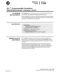
A functional diagram of a typical MetraByte sensor module is shown in Figure
2.1 . It is a useful reference designed to illustrate the data path in the module
and to explain the function of many of the modute's commands.
The first step is to acquire the sensor signal and convert it to digital data. In
Figure 2.1, all the signal conditioning circuitry has been lumped into one block,
the analog-to-digital converter (ND).
Autozero and autocalibration is performed
internally and is transparent to the user.
The full-scale output of the AID converter may be trimmed using the Trim Span
(TS) command. The TS command adjusts calibration values stored internally in
the EEPROM. The TS command should only be used to trim the accuracy of
the unit with a laboratory standard reference applied to the sensor input.
The trimmed data now flows into either of two digital filters. The filter selection is
performed automatically by the microprocessor after every A/Dconversion. The
filter selection depends on the difference of the current A/D output data and the
previous data stored in the output data register. If the least significant decimal
digit from the AID differs from the old output data by more than 10 counts, the
large signal filter is selected. If the change is less than 10 counts, the small
signal filter is used.
The two-filter system allows for different degrees of filtering depending on the
rate of the input change. For steady-state signals, the small-signal filter
averages out noise and small input changes to give a stable steady-state
output. The large-signal filter is activated by step changes or very noisy input
signals. The time constants for the two filters can be specified independently
with the Setup (SU) command. The filter values are stored in nonvolatile
memory. Typically, the srnall-signal filter is set to a larger time constant than the
large-signal fitter. This gives very good noise rejection along with fast response
to step inputs.
The MetraByte modules allow for user selectable output scaling in "C or "F on
temperature data. This selection is depicted in Figure 2.1 as a switch following
the digital filters. The defauk scaling in the modules is O C , but this may be
converted to O F by feeding the data through a conversion routine. The switch
position is controlled by a bit in the setup data and may be changed with the
Setup (SU) command. The scaling selection is nonvolatile. For nontemperature applications, the "c position should always be selected.
The scaled data is summed with data stored in the Output Offset Register to
obtain the final output value. The output offset is controlled by the user and
serves many useful purposes. The data in the Output Offset Register may be
used to trim any offsets caused by the input sensor. It may be used to null out
undesired signal such as a tare weight. The Trim Zero (TZ)command is used to
adjust the output to any desired value by loading the appropriate data value in
the offset register. The data in the offset register is nonvolatile.
The output offset may also be modified using the Set Point (SP) command. The
data value specified by the SP command is multiplied by -1 before being
loaded into the register. The Set Point command specifies a null value that is
subtracted from the input data. The output reading becomes a deviation value
from the downloaded setpoint. This feature is very useful in on-off controllers as
described in the digital I/O section of this manual.
The value stored in the offset register may be read back using the Read Zero
(RZ) command. Data loaded in with the SP command will be read back with the
sign changed. The output register may be reset to zero with the Clear Zero (CZ)
command.
The output data may be read with the Read Data (RD) command. In some
cases when a computer is used as a host, it may be possible to read back the
same data value several times before it is updated with a new A/D conversion.
To guarantee that the same data is not read more than once, the New Data
(ND) command may be used. Each time an RD or ND command is performed,
the New Data Flag is cleared. The flag is set each time the output data register
is loaded as the result of a new A/D conversion. The ND command will wait
until the flag is set before it outputs the data reading.
The remainder of Figure 2.1 depicts several functions known collectively as the
Digital I/O section. It consist of a versatile alarm function, an event counter and
general-purpose digital inputs and outputs. These functions are described in
detail in the Digital I/O section.
The heart of the alarm section consists of two registers that are used to store
high and low alarm limit values. These registers may be down-loaded with data
values by using the HI and LO alarm commands. The alarm values are loaded
with the same data format that is used with the output data. The high and low
alarm registers are nonvolatile so they will not be lost when the unit is powered
down. The values contained in the alarm registers may be read back at any
time with the Read High (RH) and Read tow (RL) commands.
The data held in the alarm registers is continually compared with the calculated
output data. The result of the comparison is used to trip alarms that may be
used as control outputs. The high alarm is turned on when the output data
exceeds the high limit value. The low alarm is activated if the output data is less
than the low alarm value. Each alarm has two user selectable modes, either
Momentary (M) or Latching (L). Momentary alarms are activated only while the
alarm condition is met; if the output data returns within limits, the alarm is turned
off. Conversely, when latching alarms are activated, they remain on even if the
2-2
output data returns within limits. Latching alarms are turned off with the Clear
Alarms (CA) command or ifthe opposite alarm limit is exceeded.
The state of the alarms may be read with the Digital Input (DI) command. Also,
the alarm outputs may be used to activate digital outputs on the module
connector to turn on alarms or to perform simple control functions. To help limit
the number of terminals required on the module connector, the alarm outputs
are shared with the general purpose digital output bits DO0 and D01. To
connect the alarm outputs to the connector, the Enable Alarm (EA) command is
used. The connector pins may be switched back to the general-purpose digital
outputs using the Disable Alarms (DA) command. The ENDA selection is
nonvolatile.
The general-purpose digital outputs are open-collector transistor switches that
may be controlled by the host with the Digital Output (DO)command. They are
designed to activate external solid-state relays to control AC or DC power
circuits. The output may also be used to interface to other logic-level devices.
The number of digital outputs available depends on the module type, with eight
being the maximum.
The Digital Input (DI) command is used to sense the logic levels on the digital
input pins DIO-D17. The digital inputs are used to read logic levels generated by
other devices. They are also useful to sense the state of electro-mechanical
limit switches. The number of digital inputs vanes with the module type.
The DIO input is shared with the input to the Event Counter. The Event Counter
is used to accumulate the number of positive transitions that have occurred on
the DWEV connector pin. The counter can accumulate up to 9999999
(decimal) events and may be read with the Read Events (RE) command. The
counter input is filtered and uses a Schmitt-trigger input tc provide a bouncefree input for mechanical switches. The counter value may be zeroed with the
Clear Events (CE)
command.
2-3
7
W
a
I
I
I
I
a
a
Y
1
a
N
c
L
VI
N
u
t
w
-%-
2-4
..
W
u
4
P
'I
W
0
CHAPTER 3
COMMUNICATIONS
Introduction
The M1000 series of interface modules has been carefully designed to be easy
to interface to all popular computers and terminals. All communications to and
from the modules are performed with printable ASCII characters. This allows
the information to be processed with string functions common to most high-level
languages such as BASIC. For computers that support standard interfaces such
as RS-232C, no special machine language software drivers are necessary for
operation. The modules car, also be connected to auto-answer modems for
long-distance operation without the need for a supervisory computer. The ASCII
format also makes system debugging easy with a dumb terminal.
The MetraByte system is designed to allow multiple modules to be connected to
a communications port with a single 4-wire cable. Up to 32 RS-485 modules
may be strung together on one cable; 124 with repeaters. A practical limit for RS232C units is about ten, although a string of 124 units is possible. The modules
communicate with the host on a polling system; that is, each module responds
to its own unique address and must be interrogated by the host. A module can
never initiate a communications sequence. A simple command/response
protocol must be strictly observed to avoid communications collisions and data
errors.
Communications to the M i 000 modules is performed with two-character ASCII
command codes such as RD to Read Data from the analog input. A complete
description of all commands is given in the Command Set section. A typical
commandresponse sequence would look like this:
Command: $1RD
Response: *+00123.00
A commandresponse sequence is not complete until a vatid response is
received. The host may not initiate a new command until the response from a
previous command is complete. Failure to observe this rule will result in
communications collisions. A valid response can be in one of three forms:
1) a normat response indicated by a ' * ' prompt
2) an error message indicated by a ' ?' ' prompt
3)a communicationstime-out error
When a module receives a valid command, it must interpret the command,
perform the desired function, and then communicate the response back to the
host. Each command has an associated delay time in which the module is busy
calculating the response. If the host does not receive a response in an
appropriate amount of time specified in Table 3.1, a communications time-out
error has occurred. After the communications time-out it is assumed that no
response data is forthcoming. This error usually results when an improper
command prompt or address is transmitted.
The following table lists the timeout specification for each command:
Mnemonic
Timeout
DI,DO,RD ,WE
10 ms.
ND
See text
100 ms.
All other commands
Table 3.1 Response Timeout Specifications.
This timeout specification indicates the turn-around time from the receipt of a
command to when the module will start to transmit a response.
RS-232C
RS-232C is the most widely used communications standard for information
transfer between computing equipment. RS-232C versions of the M1000 will
interface to virtually all popular computers without any additional hardware.
Although the RS-232C standard is designed to connect a single piece of
equipment to a computer, the MetraByte system allows for several modules to
be connected in a daisy-chain network structure.
The advantages offered by the RS-232C standard are:
1) widety used by all computing equipment
2) no additional interface hardware in most cases
3) separate transmit and receive lines ease debugging
4) compatible with dumb terminals
However, RS-232C suffers from several disadvantages:
1) low noise immunity
2) short usable distance - 50 to 200 feet
3) maximum baud rate - 19200
4) greater communications delays in multiple-modulesystems
5) less reliable-loss of one module results in no communications
6) wiring is slightly more complex than RS-485
7) host software must handle echo characters
3-2
Single Module Connection
Figure 1.1 shows the connections necessary to attach one module to a host.
Use the Default Mode to enter the desired address, baud rate, and other setups
(see Setups). The use of echo is not necessary when using a single module on
the communications line.
Multi-party Connection
RS-232C is not designed to be used in a multiparty system; however the Ml000
modules can be daisychained to allow many modules to be connected to a
single communications port. The wiring necessary to create the daisy-chain is
shown in Figure 3.1. Notice that starting with the host, each Transmit output is
wired to the Receive input of the next module in the daisy chain. This wiring
sequence must be followed until the output of the last module in the chain is
wired to the Receive input of the host. All modules in the chain must be setup to
the same baud rate and must echo ail received data (see Setups). Each module
must be setup with its own unique address to avoid communications collisions
(see Setups). In this network, any characters transmitted by the host are
received by each module in the chain and passed on to the next station until the
information is echoed back to the Receive input of the host. In this manner all
the commands given by the host are examined by every module. If a module in
the chain is correctly addressed and receives a valid command, it will respond
by transmitting the response on the daisy chain network. The response data will
be ripple through any other modules in the chain until it reaches its final
destination, the Receive input of the host.
The daisy chain network must be carefully implemented to avoid the pitfalls
inherent in its structure. The daisy-chain is a series-connected structure and any
break in the communications link will bring down the whole system. Several
rules must be observed to create a working chain:
1. All wiring connections must be secure; any break in the wiring, power,
ground, or communicationswill break the chain. All modules must be
plugged into their respective connectors.
2. All modules must be setup for the same baud rate.
3. All modules must be setup for echo.
3-3
I
+10 t o
+
To +Vs
+30Vdc -
RS-232
Figure 3.1. RS-232 Da sy Chain Network
Software Considerations
I f the host device is a computer, it must be able to handle the echoed command
messages on its Receive input along with the responses from the module. This
can usually be handled by software string functions by observing that a module
response always begins with a ' * ' or ' ? ' character and ends with a carriage
return.
A properly addressed MI000 module in a daisy chain will echo all of the
characters in the command including the terminating carriage return. Upon
receiving the carriage return, the module will immediately calculate and transmit
the response to the command. During this time, the module will not echo any
characters that appear on its receive input. However, if a character is received
during this computation period, it will be stored in the module's internal receive
buffer. This character will be echoed after the response string is transmitted by
the module. This situation will occur if the host computer appends a linefeed
character on the command carriage return. In this case the linefeed character
will be echoed after the response string has been transmitted.
The daisy chain also affects the command timeout specifications. When a
module in the chain receives a character it is echoed by retransmitting the
character through the module's internal UART. This method is used to provide
more reliable communications since the UART eliminates any slewing errors
caused by the transmission lines. However, this method creates a delay in
3-4
propagating the character through the chain. The delay is equal to the time
necessary to retransmit one character using the baud rate setup in the module:
Baud Rate
300
600
1200
2400
4800
9600
Delay
33.30 ms.
16.70 ms.
8.33 ms.
4.1 7 ms.
2.08 ms.
1.04 ms.
One delay time is accumulated for each module in the chain. For example, if
four modules are used in a chain operating at 1200 baud, the accumulated
delay time is 4 X 8.33 ms. = 33.3 ms. This time must be added to the times
listed in Table 3.1 to calculate the correct communications time-out error.
For modules with RS-232C outputs, the programmed communications delay
specified in the setup data (see Setup section) is implemented by sending a
NULL character (00) followed by an idle line condition for one character time.
This results in a delay of two character periods. For longer delay times
specified in the setup data, this sequence is repeated.
Programmed
communications delay is seldom necessary in an RS-232C daisy chain since
each module in the chain adds one character of communications delay.
Changing 8aud Rate
It is possible to change the baud rate of an RS-232C daisy chain on-line. This
process must be done carefully to avoid breaking the communications link.
1. Use the Setup (SU) command to change the b m d rate setup on each
module in the chain. Be careful not to generate a reset during this process. A
reset can be caused by the Remote Reset (RR) command, a line break, or
power interruptions.
2. Verify that all the modules in the chain contain the new baud rate setup
using the Read Setup (RS) command. Every module in the chain must be setup
for the same baud rate.
3. Remove power from all the modules for at least 10 seconds. Restore
power to the modules. This generates a power-up reset in each module and
loads in the new baud rate.
4. Change the host baud rate to the new value and check
communications.
5. Be sure to compensate for a different communications delay as a result
of the new baud rate.
~~
Using A Daisy-Chain With A Dumb Terminal
A dumb terminal can be used to communicate to a daisy-chained system. The
terminal is connected in the same manner as when using a computer as a host.
Any commands typed into the dumb terminal will be echoed by the daisy chain.
To avoid double characters when typing commands, set the terminal to full
duplex mode or turn off the local echo. The daisy chain will provide the input
command echo.
RS-485
RS-485 is a recently developed communications standard to satisfy the need for
multidropped systems that can communicate at high data rates over long
distances. RS-485 is similar to RS-422 in that it uses a balanced differential pair
of wires switching from 0 to 5 volts to communicate data. RS-485 receivers can
handle common mode voltages from -7V to +12V without loss of data, making
them ideal for transmission over great distances. RS-485 differs from RS-422 by
using one balanced pair of wires for both transmitting and receiving. Since an
RS-485 system cannot transmit and receive at the same time it is inherently a
half-duplex system.
RS-485 offers many advantages over RS-232C:
1) balanced line gives excellent noise immunity
2) can be used to to communicate with M1 000 modules at 38400 baud
3) communications distances up to 10,000 feet.
4) true multidrop; modules are connected in parallel
5) modules can be disconnected without breaking communications
6)up to 32 modules on one line; 124 with repeaters
7) no communications delay due to multiple modules
8) simplified wiring using standard telephone cable
Of course, RS-485 does have its disadvantages. Very few computers or
terminals have built-in support for this new standard. Interface boards are
available for the IBM PC and compatibles and other RS-485 equipment will
become available as the standard gains popularity. This means that an RS-485
system usually requires the extra expense of an interface.
Metra8yte Cop. offers interface converters to convert RS-232C and RS-422 to
RS-485.For systems that require more than a few modules, long wiring
distances, or high speed, RS-485 is recommended
3-6
Host
RS-485
-
B= Black
. .
R= Red
G= Green
DO(G)
v= Yellow
GNDlB>
ra
10,000
Feet
up
+
T
I
F i g u r e 3.2. RS-485 M u I t i d r o p N e t w o r k .
RS-485Multidrop System
Figure 3.2 illustrates the wiring required for multiple-module RS-485 system.
Notice that every module has a direct connection to the host system. Any
number of modules may be unplugged without affecting the operation of the
remaining modules. Each module must be setup with a unique address and the
addresses can be in any order. All RS-485 modules must be setup for no echo
to avoid bus conflicts (see Setup). Also note that the connector pins on each
module are labelled with notations (B), (R), (G), and (Y). These notaticns
designate the colors used on standard 4-wire telephone cable:
Label
(6)GND
(R) v+
(G) DATA*
(Y) DATA
Color
Black
Red
Green
Yellow
This color convention is used on all MetraByte RS-485 equipment to simplify
installation. If standard 4-wire telephone cable is used, it is only necessary to
match the labeled pins with the wire cotor to guarantee correct installation.
The notation ' ' on the label DATA* is simply used to indicate the complement
of DATA (negative true).
To minimize unwanted reflections on the transmission line, the bus should be
arranged as a line going from one module to the next. 'Tree' or random
structures of the transmission line should be avoided. For wire runs greater than
500 feet total, the end of the line should be terminated with a 100 ohm resistor
connected between DATA and DATA*.
3-7
Special care must be taken with very long busses (greater than 1000 feet) to
ensure error-free operation. Long busses must be terminated as described
above. The use of twisted cable for the DATA and DATA* lines will greatly
enhance signal fidelity. Use parity and checksums along with the '#' form of all
commands to detect transmission errors. In situations where many modules are
used on a long line, voltage drops in the power leads becomes an important
consideration. The GND wire is used both as a power connection and the
common reference for the transmission line receivers in the modules. Voltage
drops in the GND leads appear as a common-mode voltage to the receivers.
The receivers are rated for a maximum of -7V. of common-mode voltage. For
reliable operation, the common mode voltage should be kept below -5V. The
resistance of 20 gauge wire commonly used in telephone cable is about 10
ohms per 1000 feet. The maximum current draw from a single module is 75 ma.
Using Ohm's Law, the maximum allowable resistance in the GND lead to be
within the -5V. common-mode condition is 66.7 ohms. For 20 gauge wire this
results in a maximum bus length of 6670 feet for a single module. These
calculations can be reduced to a general rule-of-thumb by taking the number of
modules on the bus and multiplying it by the bus length in feet. The resultant
number must be less than the number given in the following Table :
Wire Gauge
Maximum modules X feet
22
4000
20
18
6000
i0000
Communications Delay
All M1000 modules with RS-485outputs are setup at the factory to provide two
units of communications delay after a commacb has bee:: received (see Setup
section). This delay is necessary when using host computers that transmit a
carriage return as a carriage return-linefeed string. Without the delay, the
linefeed character may collide with the first transmitted character from the
module, resulting in garbled data. If the host computer transmits a carriage
return as a single character, the delay may be set to zero to improve
communications response time.
CHAPTER 4
COMMAND SET
The M1000 modules operate with a simple commandhesponse protocol to
control all module functions. A command must be transmitted to the module by
the host computer or terminal before the module will respond with useful data.
A module can never initiate a communications sequence. A variety of commands exists to exploit the full functionality of the modutes. A list of available
commands and a sample format for each command is listed in Table 4.1.
Command Structure
Each command message from the host must begin with a command prompt
character to signal to the modules that a command message is to follow. There
are two valid prompt characters; a dollar sign character ($) is used to generate a
short response message from the module. A short response is the minimum
amount of data necessary to complete the command. The second prompt
character is the pound sign character (#) which generates long responses (the
long response format will be covered a little later).
The prompt character must be followed by a single address character
identifying the module to which the command is directed. Each module
attached to a common communications port must be setup with its own unique
address so that commands may be directed to the proper unit. Module
addresses are assigned by the user with the Setup (SU) command. For best
resub, use printable ASCII characters such as '1' (ASCII $31) or 'A' (ASCII
$41) are the best choices for address characters.
The address character is followed by a two-character command which identifies
the function to be performed by the module. All of the available commands are
listed in Table 4.1 along with a shcrt function definition. All commands are
described in full later in this section. Commands must be transmitted as uppercase characters.
A two-character checksum may be appended to any command message as a
user option. See 'Checksum' section below.
All commands must be terminated by a Carriage Return character (ASCII $OD).
(In all command examples in this text the Carriage Return is either implied O F
denoted by the symbol 'CR'.)
Data Structure
Many commands require additional data values to complete the command
definition as shown in the example commands in Table 4.1. The particular data
necessary for these commands is described in full in the cornpIete command
descriptions.
The most common type of data used in commands and responses is analog
data. Analog data is always represented in the same format for all models in
the MlOOO series. Analog data is represented as a nine-character string
consisting of a sign, five digits, decimal point, and two additional digits. The
string represents a decimal value in engineering units.
Examples:
-1-12345.68
+00100.00
-00072.1 0
-00000.00
When using commands that require analog data as an argument, the full ninecharacter string must be specified, even though some digits may not be
significant. Failure to do this will result in a SYNTAX ERROR.
Analog data responses from the module will always be transmitted in the ninecharacter format. This greatly simplifies software parsing routines since all
analog data is in the same format for all module types.
In many cases, some of the digits in the analog data may not be significant. For
instance, the M1300 thermocouple input modules feature 1 degree output
resolution. A typical analog data value from this type of module could be
-1-00123.00
. The two digits to the right of the decimal point have no significance in this particular model. However, the data format is always adhered
to in order to maintain compatabitity with other module types.
The maximum computational resolution of the rnodute is 16 bits, which is less
than the resolution that may be represented by an analog data variable. This
may lead to round-off errors in some cases. For example, an alarm value may
be sto:ed in a M1OCO module using the 'HI' arnmand:
Command: $1HI+i2345.67M
Response:
The alarm value may then be read back with the Read High (RH) command:
Command: $1 RH
Response: *+12345.60M
It appears that the data read back does not match the value that was originally
saved. The error is caused by the fact that the value saved exceeds the
computational resolution of the module. This type of round-off error only
appears when large data values saved in the module's EEPROM are read back.
In most practical applications, the problem is nonexistent.
Overload values of analog data are represented by 49999.99 and -99999.99 4-2
Data read back from the Event Counter with the Read Events (RE) command is
in the form of a seven-digit decimal number with no sign or decimal point.
Round-off errors do not occur on the event counter. For example:
Command: $1RE
Response: '0000123
The Digital Input, Digital Output, and Setup commands use hexadecimal
representations of data. The data structures for these commands are detailed in
the command descriptions.
Write Protection
Many of the commands listed in Table 4.1 are under the heading of 'Write
Protected Commands'. These commands are used to alter setup data in the
module's EEPROM. These commands are write protected to guard against accidental loss of setup data. All write-protected commands must be preceded by a
Write Enable (WE) command before the protected command may be executed.
Miscellaneous Protocol Notes
The address character must transmitted immediately after the command prompt
character. After the address character the module will ignore any character
below ASCII $23 (except, of course, CR). This allows the use of spaces (ASCII
$20) within the command message for better readability if desired.
The length of a command message is limited to 20 printable characters. if a
properly addressed module receives a command message of more than 20
characters the module will abort the whole command sequence and no
response will result.
If a properly addressed module receives a second command prompt before it
receives a CR, the command will be aborted and no response will result.
Response Structure
Response messages from the M1000 module begin with either an asterisk ' '
(ASCII $2A) or a question mark ' ? ' (ASCII $3F) prompt. The ' ' prompt
indicates acknowledgment of a valid command. The ' ? ' prompt precedes an
error message. All response messages are terminated with a CR. Many
commands simply return a single '
' character to acknowledge that the
command has been executed by the module. Other commands send data
information following the ' * ' prompt. The response format of all commands
may be found in the detailed command description.
The maximum response message length is 20 characters.
4-3
A commandhesponse sequence is not complete until a valid response is
received. The host may not initiate a new command until the response from a
previous command is complete. Failure to observe this rule will result in
communications collisions. A vaIid response can be in one of three forms:
1) a normal response indicated by a ' ' prompt
2) an error message indicated by a ' ? ' prompt
3) a communications time-out error
When a module receives a valid command, it must interpret the command,
perform the desired function, and the communicate the response back fo the
host. Each command has an associated delay time in which the module is busy
calculating the response. If the host does not receive a response in an
appropriate amount of time specified in Table 4.1, a communications time-out
error has occured. After the communications time-out it is assumed that no
response data is forthcoming. This error usually results when an improper
command prompt or address is transmitted.
Long Form Responses
When the pound sign ' # ' command prompt is used, the module will respond
with a 'long form' response. This type of response will echo the command
message, supply the necessary response data, and will add a two-character
checksum to the end of fhe message. Long form responses are used in cases
where the host wishes to verify the command received by the module. The
checksum is included to verify the integrity of the response data. The ' # '
command prompt may be used with any command. For example:
Command: $1 RD
Response: *+00072.10
(short form)
Command: #I RD
(long form)
Response: '1 RD+00072.1OA4 (A4shecksum)
Checksum
Checksum, a two character hexadecimal value added to the end of a message,
verifies that the message received is exactly the same as the message sent.
The checksum ensures the integrity of the information communicated.
Command Checksum
A two-character checksum may be appended to any command to the M1000
module as a user option. When a module interprets a command, it looks for the
two extra characters and assumes that it is a checksum. If the checksum is not
present, the module will perform the command normally. If the two extra
characters are present, the module will calculate the checksum for the
4-4
message. If the calculated checksum does not agree with the transmitted
checksum, the module will respond with a 'BAD CHECKSUM' error message
and the command will be aborted. If the checksums agree, the command will
be executed. If the module receives a single extra character, it will respond with
a 'SYNTAX ERROR' and the command will be aborted. For example:
Command: $1 RD
Response: *+00072.10
(no checksum)
Command: $1RDEB
Response: *+00072.10
(with checksum)
Command: $1RDAB
(incorrect checksum)
Response: ?I
BAD CHECKSUM
(one extra character)
Command: $1RDE
Response: ? I SYNTAX ERROR
Response Checksums
If the long form ' # ' version of a command is transmitted to a module, a
checksum will be appended to the end of the response. For example:
Command: $1RD
Response: *+00072.10
(short form)
Command: #
RD
I
(long form)
Response: *I RD+00072.1OA4 (A4=checksum)
Checksum Calculation
The checksum is calculated by summing the hexadecimal values of all the
ASCII characters in the message. The lowest order two hex digits of the sum
are used as the checksum. These two digits are then converted to their ASCII
character equivalents and appended to the message. This ensures that the
checksum is in the form of printable characters.
Example: Append a checksum to the command #I DOFF
Characters:
ASCII hexvalues:
Sum (hex addition)
# 1 D O F F
23 31 44 4F 46 46
23 + 31 + 44 + 4F + 46 + 46 = 173
The checksum is 73 (hex). Append the characters 7 and
#1DOFF73
3 to the end
of the message:
4-5
Example: Verify the checksum of a module response *1RD+00072.1OA4
The checksum is the two characters preceding the CR: A4
Add the remaining character vafues:
*
l
R
D
+
O
O
O
7
2
.
1
0
2A+ 31 + 52+ 44+ 2B+ 30+ 30+ 30+ 37+ 32+ 2E+ 31+ 30 = 2A4
The two lowest-order hex digits of the sum are A4 which agrees with the
transmitted checksum.
Note that the transmitted checksum is the character string equivalent to the
calculated hex integer. The variables must be converted to like types in the host
software to determine equivalency.
If checksums do not agree, a communications error has occurred.
If a module is setup to provide linefeeds, the linefeed characters are not
included in the checksum calculation.
Panty bits are never included in the checksum calculation.
4-6
Table 4.1 M l O O O Command Set
Command and Definition
DI
DO
ND
RD
RE
RL
RH
RS
Rz
WE
Read AlarmdDigital Inputs
Set Digital Outputs
New Data
Read Data
Read Event Counter
Read Low Alarm Value
Read High Alarm Value
Read Setup
Read Zero
Write Enable
Typical
Command
Message
( $ prompt)
$1 DI
$1 DOFF
$1ND
$1 RD
$1 RE
$1 RL
$1 RH
$1 RS
$1 Rz
$1WE
Typical
Response
Message
*0003
*
*+00072.00
*+00072.00
*0000107
*+ooooo.oo L
*+00510.00 L
*31070142
*+ooooo.oo
Write Protected Commands.
CA
CE
cz
DA
€A
H1
LO
RR
su
SP
TS
Tz
Clear Alarms
Clear Events
Clear Zero
Disable Alarms
Enable Alarms
Set High Alarm Limit
Set Low Alarm Limit
Remote Reset
Setup Module
Set Setpoint
Trim Span
Trim Zero
$1 CA
$1 CE
$1cz
$1 DA
$1 EA
$1 HI+I 2345.67L
$1 L0+12345.671_
$1 RR
$1 SU31070l42
$1 SP+00600.00
$1 TS+00600.00
$1 Tz+ooooo.oo
*
*
rc
*
t
*
*
*
*
4-7
MI000 User Commands
Note that in all command and response examples given below, a carriage
return is implied after every character string.
Clear Alarms (CA)
The clear alarms command turns both the HI and LO alarms OFF. This command does not affect the enable/disable or momentary/latching alarm conditions. The alarms will continue to be compared to the input data after the GA
command is given. In cases where the alarm condition persists, the alarms will
be set at the end of the next input data conversion. The primary purpose of the
CA command is to clear latching alarms. See the Alarms section for more
information.
Command: $1CA
Response: *
Command: #I CA
Response: *1CADF
Clear Events (CE)
The Clear Events ccmmand clears the events counter to 0000000.
Command: $1CE
Response: *
Command: #1
Response: *lCEE3
Note: When the events counter reaches 9999999, it stops counting. A CE command must be sent to resume counting.
Clear Zero (CZ)
The Clear Zero command clears the output offset register value to +OOOOO.OO.
This command clears any data resulting from a Trim Zero (TZ) or SetPoint (SP)
command.
Command: $1CZ
Response:
Command: #1CZ
Response: *1CZF8
4- 8
Disable Alarms (DA)
Most models in the MlOOO series feature LO/DOO and HI/D01 pins on the
module connector. These pins serve a dual function and can be used to output
either the alarm outputs or digital outputs 0 and 1. The Disable Alarms
command is used to connect the digital outputs 0 and 1 to the connector pins.
The alarm settings are not affected in any way except that the alarm outputs are
disconnected from the module connector. The alarm status can still be read
with the Digital Input (DI) command. The complement to the DA command is the
Enable Alarms (EA) command.
Command: $1DA
Response: *
Command: #1 DA
Response: *I DAEO
Digital Input (DI)
The DI command reads the status of the digital inputs and the alarms. The response to the DI command is four hex characters representing two bytes of data.
The first byte contains the alarm status. The second byte contains the digital
input data.
Command: $1DI
Response: *0003
Command: #I DI
Response: *I D10003AB
Listed below are the four possible alarm states in the first digital input byte and
their hex values.
00 Both HI and LO alarms off.
01 HI alarm off. LO alarm on.
02 HI alarm on. LO alarm off.
03 Both HI and LO alarms on.
The second byte displays the hex value of the digital input status. The number
of digital inputs vanes depending on module type.
Diaital
InDuts
Data Bits
017 D16 D15 D14 D13 D12 DI1 DlQ
7
6
5
4
3
2
1
0
For example: A typical response from a $1 DI command could be: '01 FE. This
response indicates that the HI alarm is off, the LO alarm is on, DIO = 0 and all
other digital inputs are = 1.
4-9
~
~~
All digital inputs that are not implemented or left unconnected are read as '1'.
Digital input 0 serves a dual function. It is both a digital input and the Event
Counter input.
When reading digital inputs with a checksum, be sure not to confuse the
checksum with the data.
Digital Output (DO)
The DO command controk eight bits of digifai outputs on the module connector.
The number of digital outputs implemented depends on the model used. The
digital outputs allow the module to control external circuits under host
command. The DO command requires an argument of two hex characters
specifying the eight bits of output data.
OutDuts
Diaital
Data Bits
DO7 DO6 DO5 DO4 003 DO2 DO1 DO0
7
6
5
4
3
2
1
0
The electrical implementation of the digital output consists of open-collector
transistors wired to the module connector. If a digital output is set to '1' the
corresponding transistor is turned on and sinks current. Note that when a digital
output bit is set to '1' the electrical output is near 0 volts. If a digital output is set
to '0'the corresponding transistor is turned off and sinks no current.
Assume a module has two digital outputs, and you wish to turn both outputs on
(sinking current). Set data bit 0 and data bit 1 to '1'. Since the module has only
two digital outputs, at1 the other bits are 'don't cares'. For example, this
command will turn both outputs 'on':
Command: $1DOFF
Response:
To turn both outputs off you could use the command:
Command: $1DO00
Response:
Digital outputs 0 and 1 share connector pins with the HI and LO alarms. The
Disable Alarms (DA) command is used to configure these pins as digital
outputs.
Digital output settings are not stored in nonvolatile memory. If a power failure
occurs, all digital outputs will be set to 0 upon power up.
The DO command is the only means of changing digital outputs. There is no
software provision to read the state of the digital outputs.
4- 10
Enable Alarms (EA)
Digital outputs DOO/LO and DOl/HI serve a dual purpose as digital outputs and
alarms. Digital output 0 is shared with the LO alarm and digital output 1 is
shared with the HI alarm. The Enable Alarms (EA) command configures the
shared outputs to indicate alarm conditions and disconnects digital outputs 0 and
I . The EA command only affects the electrical output of the alarms to the pins.
The alarm status can be read at any time with the Digital Input (DI) command.
The complement to the EA command is the Disable Alarms (DA) command.
Command: $1 EA
Response: *
Command: #1 EA
Response: *I EAEI
High Alarm Limit (HI)
The high alarm command sets the value and type of the high alarm. The data
specified by the HI command is stored in nonvolatile memory and compared with the
sensor data after every A/Dconversion. The high alarm is activated if the input data
is greater than the value stored by the HI command. The high alarm status may be
read using the Digital Input (DI) command. The alarm may be used to activate a
digital output by using the Enable Alarms (EA) command. The HI command also
specifies whether the high alarm is momentary or latching. A letter indicating the
alarm type, "L" for latching or "M" for momentary, must follow the alarm value. For
example:
Command: $1 H1+00100.00M
Response: *
Command: #
H1+00100.00M
I
Response: '1 HI+00100.00ME3
The alarm limit should be set within the output range of the module. If the alarm limit
is set beyond the output range, the alarm will be activated only on an overload
condition.
The high alarm value may be read back with the Read High Alarm (RH) command.
A latched alarm may be cleared with the Clear Alarms (CA) command. More
information on alarms may be found in the Digital I/O section.
4-11
Low Alarm Limit (LO)
The low alarm command sets the value and type of the low alarm. The dataspecified
with the LO command is stored in nonvolatile memory and compared with the sensor
data after every A/D conversion. If the input data is less than the low limit, the low
alarm is activated. The low alarm status may be read using the Digital Input (DI)
command. The alarm may be used to activate a digital output by using the Enable
Alarms (EA) command. A letter indicating the alarm type, "L" for latching or"M"for
momentary, must follow the alarm value. For example:
Command: $1LO+OOOOO.OOM
Response: *
Command: #I LO+OOOOO.OOM
Response: *ILO+OOOOO.OOMEC
The alarm limit should be set within the output range of the module. If the alarm limit
is set beyond the output range, the alarm will be activated only on an overload
co nditio n.
The low limit value may be read back with the Read Low Limit (RL) command.
More information on alarms may be found in the Digital I/O section.
New Data Command (ND)
The New Data (ND) command is avariation of the Read Data (RD) command used
to read sensor data from the module. The ND command guarantees that the output
data has not been previously read.
The M1000 module acquires analog input data eight times a second and stores the
result in the output buffer (see Figure 2.1). The Read Data (RD) command simply
reads the resuits stored in the output buffer. A fast host communicating at a high
baud rate could possibly read the output buffer several times before the information
is updated with a new A/D conversion. This results in redundant information which
may be confusing or may be a waste of host processor time.
Associated with the output buffer is the New Data Flag (see Figure 2.1). This flag
is cleared each time an RD or ND command is performed. The flag is set when the
module's microprocessor loads the output buffer with the result of the most recent
A/D conversion. The ND command will output data only when the New Data Flag
is set. If the flag is cleared when an ND command is received, the module will wait
until new data is present in the output buffer before responding to the command.
Thus, the output data obtained with an ND command is always the result of a new
AID conversion.
4-12
The ND command is especially useful with computers that handte communications
on an interrupt basis. The ND command may be used to get the maximum possible
throughput without producing redundant data.
Command: $1 ND
Response: '+00072.00
Command: #I ND
Response: '1 ND+00072.009F
A special condition exists when using the ND command with the M1600 frequency/
pulse modules. These modules differ from the other sensor input modules in that
they require an input trigger signal to obtain new data. If no signal exists on the input
of the M1600, an ND command will wait indefinitely for new data and the module will
not respond.
In order to escape this condition, a single control-C ($03) may be issued by the host
to abort the ND command. The aborted ND command will respond with the data
value currently stored in the output buffer. Be aware that on an RS-485 system, the
control-C character may interfere with the ND output data, causing a comrnunications collision.
Read Data (RD)
The read data command is the basic command used to read the buffered sensor
data. The output buffer (Figure 2.1 ) allows the data to be read immediately without
waiting for an input A/D conversion. For example:
Command: $1 RD
Response: *+00072.00
Command: #I RD
RD+00072.1OA4
Response: *I
Since the RD command is the most frequently used command in normal operation,
a special shortened version of the command is available. If a module is addressed
without a two-lettercomrnand, the module interpretsthe string as an RD command.
Command: $I
Response: *+00072.10
Command: #I
Response: '1 RD+00072.10A4
4-13
READ EVENTS (RE)
The Read Events command reads the number of events that have been accumulated in the Events Counter. The output is a seven-digit decimal number. For
example:
Command: $1RE
Response: *0000107
Command: #1 RE
Response: '1 RE00001074A
The maximum accumulated count is 9999999. When this count is reached, the
Events Counter stops counting. The counter may be cleared at any time with the
Clear Events (CE) command.
The Event Counter count is not stored in nonvolatile memory. If power is removed,
the Event Counter will reset to all 0's upon power up.
The Remote Reset (RR) command or a line break does not effect the value of the
Event Counter.
When reading the Event Counter with a checksum, be sure not to confuse the
checksum with the data.
Read High Alarm (RH)
The Read High alarmcommand readsthevalueandtypeofthe high alarm previously
loaded by the HI command. The alarm type can be either latching or momentary. A
letter indicating the alarm type, "L" for latching or "M" for momentary, will follow the
alarm value. For example:
Command: $1RH
Response: *+00510.00L
Command: #1 RH
Response: *1RH+0051O.OOLF0
The RH command may be used to verify the data loaded into nonvolatile memory by
the HI command.
4-14
Read Low Alarm (RL)
The Read Low alarm command reads the value and type of the low alarm. The alarm
type can be either latching or momentary. A letter indicating the alarm type, "L" for
latching or "M" for momentary, will follow the alarm value. For example:
Command: $1 RL
Response: *+OOOOO.OOL
Command: #1 RL
Response: *IRL+OOOOO.OOLEE
The RLcommand may be used to verify data loadedinto the nonvolatile memory with
the LO command.
Remote Reset (RR)
The reset command allows the host to perform a program reset on the module's
microprocessor. This may be necessary ifthe module's internal program isdisrupted
by static or other electrical disturbances. Once a reset command is received, the
module will recalibrate itself. The calibration process takes approximately 2
seconds. For example:
Command: $1RR
Response: *
Command: #1 RR
Response: *1 RRFF
In general, the state of the digital outputs and the event counter will not be affected
by the RR command. However, if data in the microprocessor's RAM (Random
Access Memory) has been lost, the RR command will result in a full power-up reset.
Any commands sent to the module during the self-calibration sequence will result in
a NOT READY error.
4-15
Read Setup (RS)
The read setupcommand reads backthe setup information loaded into the module's
nonvolatile memory with the Setup (SU) command. The response to the RS
command is four bytes of information formatted as eight hex characters.
Command: $1RS
Response: *31070142
Command: #I RS
Response: '1 RS3107014292
The response contains the module's channel address, baud rate, averaging constants, "C/"F, and other parameters. Refer to the setup command (SU), and the
Setup section of this manual for a full list of parameters contained within the setup
information.
When readingthe setup with achecksum, be sure not to confuse the checksum with
the setup information.
Read Zero (RZ)
The Read Zero command reads back the value stored in the Output Offset Register
(Figure 2.1).
Command: $1RZ
Response: *+OOOOO.OO
Command: #1 RZ
Response: *1RZ+OOOOO.OOBO
The data read back from the Output Offset Register may be interpreted in several
ways. The commands that affect this value are the Trim Zero (TZ), SetPoint (SP),
and Clear Zero (CZ).
4-16
Setpoint (SP)
The data specified by the setpoint command is multiplied by -1 and loaded into the
Output Offset Register (Figure 2.1). The SP command is useful in on-off controller
applications and is described in detail in the Digital I/O section of this manual. The
SP command may be used to null out sensor data to obtain adeviation output when
the RD or ND commands are used.
Command: $1SP+00450.00
Response: *
Command: #1SP+00450.00
Response: *1SP+00450.00BO
It is possible to load setpoint data that is beyond the output range of the sensor. In
this case, the setpoint can never be reached by the sensor data unless an overload
is present.
To clear a setpoint, use the Clear Zero (CZ) command.
The SP command will write over any data written into the Output Offset Register by
the Trim Zero (TZ) command. If the Output Offset Register is used as a trim value,
this must be accounted for by the host before using the SP command. The value
stored in the offset register may be read back using the Read Zero (RZ) command.
The setpoint data or trim data in the Output Offset Register is saved in nonvolatile
memory.
Setup Command (SU)
Each M I 000 module contains an EEPROM (Electrically Erasable Programmable
Read Only Memory) which is used to store module setup information such as
address, baud rate, parity, etc. The EEPROM is a special type of memory that will
retain informationeven if power is removedfrom the module. The EEPROM is used
to replace the usual array of DIP switches normally used to configure electronic
equipment.
The Setup command is used to modify the user-specified parameters contained in
the EEPROM to taylor the module to your application. Since the Setup command
is so important to the proper operation of a module, a whole section of this manual
has been devoted to its description. See Section 5.
4-17
The SU command requires an argument of eight hexadecimal digits to describe four
bytes of setup information:
Command: $1SU31070182
Response: *
Command: #1SU31070182
Response: '1 SU31070l8299
Trim Span (TS)
The trim span command is the basic means of trimming the accuracy of a M1000
sensor module. The TS command loads acalibration factor into nonvolatile memory
to trim the full-scale output of the signal conditioning circuitry. It is intended only to
compensate for long-term drifts due to aging of the analog circuits, and has a useful
trim value of +lo% of the nominal calibration set at the factory. It is not intended to
be used to change the basictransfer function of the module. Full information on the
use of the TS command may be found in the Calibration section.
Command: $1TS+00500.00
Response: *
Command: #1TS+00500.00
Response: *I TS+00500.00BO
Caution! TS is the only command associated with the span trim. There is no
provision to read back or clear erroneous information loaded by the TS command.
Unwarranted use of the TS command may destroy the calibration of the unit which
can only be restored by using laboratory calibration instruments in a controlled
environrne nt .
Trim Zero (TZ)
The Trim Zero command is used to load a value into the Output Offset Register
(Figure2.1) to null out an undesirable offset in the output data. It may be used totrirn
offsets created by sensors such as strain gages. It may also be used to null out data
to create a deviation output.
Example: Assume a M1511 bridge input module is being used with a load delb r
weight measurement. An inital reading of the load cell with no weight
applied may reveal an initial offseterror:
Command: $1 RD
Response: *+00005.00
4-18
With no weight applied, we would like to trim the output to read zero. To t r i m
the system, use the TZ command and specify the desired output reading:
Command: $1TZ+OOOO0.00
Response: *
(zero output)
The TZ command will load a data value into the Output Offset Register to force the
output to read zero. The module wiIl compensate for any previous value loaded into
the Output Offset Register. If another output reading is taken, it will show that the
offset has been eliminated:
Command: $1 RD
Response: *+OOOOO.OO
Although the TZ command is most commonly used to null an output to zero, it may
be used to offset the output to any specified value. Assume thatwith the previously
nulled load cell system we performed this command:
Command: $1TZ-000100.00
Response: *
The new data output with no load applied would be:
Command: $1 RD
Response: *-000100.00
The load cell output is now offset by -100.
The offset value stored by the TZ command is stored in nonvolatile memory and may
be read backwith the ReadZero (RZ) commandandcleared withtheclearzero (CZ)
command.
The SetPoint (SP) command will write over any value loaded by the TZ command.
Write Enable (WE)
Each MetraByte module is write protected against accidental changing of alarms,
limits, setup, or span and zero trims. To change any of these write protected
parameters, the WE command must precede the write-protected command. The
response to the WE command is an asterisk indicating that the module is ready to
accept a write protected command. After the write-protectedcommand is successfully completed, the module becomes automatically write disabled. Each write-
4-19
protected command must be preceded individually with a WE command. For
example:
Command: $1WE
Response:
Command: #I WE
Response: *I WEF7
If a module is write enabled and the execution of a command results in an error
message other than WRITE PROTECTED, the module remains write enabled until
a command is successfully completed resulting in an ' * prompt. This lets the user
correct the command error without having to execute another WE command.
I
ERROR MESSAGES
The M1000 modules feature extensive error checking on input commands to avoid
erroneous operation. Any errors detected will result in an error message and the
command will be aborted.
All error messages begin with "?,,,followed by the channei address, aspace, and the
error description. The error messages have the same format for either the $ or '
# I command prompts. For example:
?I SYNTAX ERROR
There are eight possible error messages, and each error message description
begins with a different character. This makes it easy for a computer program to
identify the error without having to read the entire string.
ADDRESS ERROR
There are four ASCII values that are illegal foruse asamoduleaddress: NULL($OO),
CR ($OD), $ ($24), and # ($23). The ADDRESS ERROR will occur when an attempt
is made to load an illegal address into a module with the Setup (SU) command. An
attempt to load an address greater than $7F will also produce an error.
BAD CHECKSUM
This error is caused by an incorrect checksum included in the command string. The
module recognizes any two hex characters appended to a command string as a
checksum. Usually a BAD CHECKSUM erroroccurs due to noise or interference on
the communications line. In many cases, repeating the command will solve the
problem. If the error persists, either the checksum is being calculated incorrectly or
4-20
there is a problem with the communications channel. In some cases, more reliable
transmissions may be obtained by using a lower baud rate.
COMMAND ERROR
This erroroccurs when the two-charactercommand is not recognizedby the module.
Often this error results when the command is sent with lower-case letters. All valid
commands are upper-case.
NOT READY
If a module is reset, it performs a self-calibration routine which takes 2-3 seconds to
complete. Any commands sent to the module during the self-calibration period will
result in a NOT READY error. When this occurs, simply wait a couple seconds and
repeat the command.
The module may be reset in four ways: a power-up reset, a Remote Reset (RR)
command, a line break, or an internal reset. All modules contain a'watchdog' timer
to ensure proper operation of the microprocessor. The timer may be tripped if the
microprocessoris executing its program improperly due to powertransients or static
discharge.
If the NOT READY error persists for more than 30 seconds, check the power supply
to be sure it is within specifications.
PARITY ERROR
A parity errorcan only occur if the module is setup with parity on (see Setup). Usually
a parity error results from a bit error caused by interference on the communications
line. Random parity errors are usually overcome by simply repeatingthe command.
If too many errors occur, the communications channel may have to be improved or
a slower baud rate may be used.
Aconsistent parity errorwill result if the host parity does not match the module panty.
In this situation, the easiest solution may be to change the parity in the host to obtain
communication. At this pointthe parity in the module may be changed to the desired
value with the Setup (SU) command.
The panty may also be changed or turned off by using the Default Mode.
SYNTAX ERROR
A SYNTAX ERROR will result if the structure of the command is not correct. This
is caused by having too few ortoo many characters, signs or decimal points missing
or in the wrong place. Table 4.1 lists the correct syntax for all the commands.
4-21
VALUE ERROR
This error results when an incorrect character is used as a numerical value. Data
values can only contain decimal digits 0-9. Hex values used in the Setup (SU) and
Digital Output (DO) commands can range from 0-F.
WRITE PROTECTED
All commands that write data into nonvolatile memory are write-protectedto prevent
accidental erasures. These commands must be precededwith a Write Enable (WE)
command or else a WRITE PROTECTED error will result.
CHAPTER 5
SETUP INFORMATION & COMMAND
The MetraByte M1000 modules feature a wide choice of user configurable
options which gives them the flexibility to operate on virtually any computer or
terminal based system. The user options include a choice of baud rate, parity,
address, and many other parameters. The particular choice of options for a
module is referred to as the setup information.
The setup information is loaded into the module using the Setup (SU)
command. The SU command stores 4 bytes (32 bits) of setup information into
if nonvolatile memory contained in the MetraByte module. Once the information
is stored, the module can be powered down indefinitely (10 years minimum)
without losing the setup data. The nonvolatile memory is implemented with
EEPROM so there are no batteries to replace.
The EEPROM has many advantages over DIP switches or jumpers normally
used for option selection. The module never has to be opened because all of
the options are selected through the communications port. This allows the
setup to be changed at any time even though the module may be located
thousands of feet away from the host computer or terminal. The setup
information stored in a module may be read back at any time using the Read
Setup command (RS).
The following options can be specified by the Setup command:
Channel address (124 values)
Linefeeds
Parity (odd, even, none)
Baud rate (300 to 38,400)
Alarm enable/disable
Alarm momentary/latching
CJC disable (M1300series)
RTD 3/4 wire (M1400 series)
Positivehegative edge trigger (Mi600 series)
FahrenheWCelsius
Echo
Communication delay (0-6 characters)
Number of displayed digits
Large-signal f i1ter constant
Small-signal filter constant
Each of these options will be described in detail below. For a quick look-up
chart on all options, refer to Tables 5.1 -4. Once you are completely familar with
the setups, you can refer to Table 5.6 for a summary of all of the setup
information.
Command Syntax
The general format for the Setup (SU) command is:
$1SU[bytel][byte S][byte 3][byte 41
A typical Setup command would look like: $1SU31070182.
Notice that each byte is represented by its two-character ASCII equivalent. In
this example, byte 1 is described by the ASCII characters '31' which is the
equivalent of binary 001 1 0001 [31 hex). The operand of a SU command must
contain exactly 8 hex (0-F) characters. Any deviation from this format will result
in a SYNTAX ERROR. The Appendix contains a convenient hex-to-binary
conversion chart.
For the purposes of describing the Setup command, 'bit 7' refers to the highestorder bit of a byte of data. 'Bit 0' refers to lowest-order bit:
'bit number':
binary data:
7 6 5 4
0 0 1 1
3 2 1 0
0 0 0 1 =$31 (hex)
The SU command is write protected to guard against erroneous changes in the
setup data; therefore each SU command must be preceded by a Write Enable
(WE) command. To abort an SU command in progress, simply send a non-hex
character (an ' X for example) to generate a SYNTAX ERROR, and try again.
caution: Care must be exercised in using the SU command. improper use
may result in changing communications parameters (address, baud rate, parity)
which will result in a loss of communications between the host and the module.
In some cases the user may have to resort to using Default Mode to restore the
proper setups. The recommended procedure is to first use the Read Setup (RS)
command to to examine the existing setup data before proceeding with the SU
command.
Byte 1
Byte 1 contains the module (channel) address. The address is stored as the
ASCII code for the string character used to address the module. In our example
command $1 SU31070080 , the first byte '31' is the ASCII code for the character
'1'. If our sample command is sent to a module, the EEPROM will be loaded
with the address 'l', which in this particular case remains unchanged. To
change the module address to '2' , byte 1 of the Setup command becomes '32''
which is the ASCII code for the character '2'. Now the command will look like
this: $lSU32070080. When this command is sent, the module address is
changed from '1' to '2.
The module will no longer respond to address 'l'..
When using the SU command to change the address of a module, be sure to
record the new address in a place that is easily retrievable. The only way to
communicate with a module with an unknown address is with the Default Mode.
The most significant bit of byte 1 (bit 7) must be set to '0'. In addition, there are
four ASCII codes that are illegal for use as an address. These codes are $00,
$OD, $24, $23 which are ASCII codes for the characters NUL, CR, $, and #.
Using these codes for an address will cause an ADDRESS ERROR and the
setup data will remain unchanged. This leaves a total of 124 possible
addresses that can be loaded with the SU command. It is highly recommended
that only ASCII codes for printable characters be used ($21 to $7E) which
greatly simplifies system debugging with a dumb terminal. Refer to Appendix A
for a list of ASCII codes. Table 5.1 lists the printable ASCII codes that may be
used as addresses.
Table 5.1 Byte 1 ASCII Printable Characters.
[EX ASCII
21
!
22
25
26
27
28
29
2A
"
%
&
'
(
1
2B
+
2c
9
2D
-
.
2E
2F
1
30
31
32
33
34
35
36
37
38
39
0
1
2
3
4
5
6
7
8
9
i E X ASCII
3A
:
38 ;
3c
<
3D
3E
3F
40
41
42
43
44
45
46
47
48
49
4A
48
4c
4D
4E
4F
50
=
>
?
@
A
B
1EX ASCII
51
Q
52
R
53
s
54
T
55
56
57
58
u
V
w
X
59
Y
c
SA
2
D
E
5B
5c
\
F
5D
5E
1
G
H
I
J
K
L
M
N
0
P
5F
60
61
62
63
64
65
66
67
-
'
a
b
c
d
e
f
g
IEX ASCII
h
68
i
69
6A
i
6B
k
I
6C
rn
6D
n
6E
6F
0
70
P
71
q
72
r
73
S
74
t
U
75
V
76
77
78
79
W
7A
78
7c
7D
7E
2
X
Y
I
1
I
5-3
Byte 2
Byte 2 is used to configure some of the characteristics of the communications
channel; linefeeds, parity, and baud rate.
Linefeeds
The most significant bit of byte 2 (bit 7) controls linefeed generation by the
module.
This option can be useful when using the module with a dumb
terminal. All responses from the M1000 are terminated with a carriage return
(ASCII $OD). Most terminals will generate a automatic linefeed when a carriage
return is detected. However, for terminals that do not have this capability, the
MetraByte module can generate the linefeed if desired. By setting bit 7 to '1' the
module will send a linefeed (ASCII $OA) before and after each response. If bit 7
is cleared (0), no linefeeds are transmitted.
When using the 'C command prompt, the linefeed characters are not included
in the checksum calculation.
Parity
Bits 5 and 6 select the panty to be used by the module. Bit 5 turns the parity on
and off. If bit 5 is 'O', the parity of the command string is ignored and the parity
bit of characters transmitted by the module is set to '1'.
If bit 5 is 'l', the parity of command strings is checked and the parity of
characters output by the module is calculated as specified by bit 6.
If bit 6 is 'O', panty is even; if bit 6 is 'l', parity is odd.
If a panty error is detected by the module, it will respond with a PARITY ERROR
message. This is usually caused by noise on the communications line.
If parity setup values are changed with the SU command, the response to the
SU command will be transmitted with the old parity setup. The new parity setup
becomes effective immediately after the response message from the SU
command.
Baud Rate
Bits 0-2 specify the cammunications baud rate. The baud rate can be selected
from eight values between 300 and 38400 baud. Refer to Tabte 5.2 for the
desired code.
The baud rate selection is the only setup data that is not implemented directly
after an SU command. In order for the baud rate to be actually changed, a
module reset must occur. A reset is performed by sending a Remote Reset (RR)
command, performing a line break (see Communications), or powering down.
This extra level of write protection is necessary to ensure that communications
to the module is not accidently lost. This is very important when changing the
baud rate of an RS-232C string. For more information on changing baud rate,
refer to the Communications section.
Let's run through an example of changing the baud
module contains the setup data value of '31 070080'.
to the SU command chart we can determine that
linefeeds, no parity, and baud rate 300. If we
command with this module we would get:
Command:
Response:
rate. Assume our sample
Byte 2 is '07'. By referring
the module is set for no
perform the Read Setup
$1RS
*31070080
Let's say we wish to change the baud rate to 9600 baud. The code for 9600
baud is '01 0' (from Table 5.2). This would change byte 2 to '02'. To perform the
SU command we must first send a Write Enable command because SU is write
protected:
Command:
Response:
Command:
Response:
$1WE
*
$1SU31020080
*
This sequence of messages is done in 300 baud because that was the original
baud rate of the module. The module remains in 300 baud after this sequence.
We c a n use the Read Setup (RS)command to check the setup data:
Command:
Response:
$1RS
*31020080
Notice that although the module is communicating in 300 baud, the setup data
indicates a baud rate of 9600 (byte 2 = '02'). To actually change the baud rate
to 9600, send a Remote Reset (RR) command (RR is write protected):
Command:
Response:
Command:
Response:
$1WE
$1RR
*
Up to this point all communications have been sent at 300 baud. The module
will not respond to any further communications at 300 baud because it is now
running at 9600 baud. At this point the host computer or terminal must be set to
9600 baud to continue operation.
5-5
If the module does not respond to the new baud rate, most likely the setup data
is incorrect. Try various baud rates from the host until the module responds.
The last resort is to set the module to Default Mode where the baud rate is
always 300.
Setting a string of RS-232C modules to a new baud rate requires special
consideration. Refer to the Communications section for instructions.
Bits 3 and 4
These two bits of byte 2 are not used by the M1000 series and should be set to
Ts.
Table 5.2 Byte 2: Linefeed, Parity and Baud Rate.
BYTE2
I FUNCTION
I
DATA BIT
~~
7 6 5 4 3 2 1 0
LINEFEED
1
NO LINEFEED
0
NO PARITY
0 0
I
I
I
I N 0 PARITY
EVEN PARITY
IODD PARITY
INOT USED
I
I
0 1
1 1
I
x x
I
I38400 BAUD
I
1 0
0 0 0
I
I
~~~
19200 BAUD
0 0 1
0 1 0
9600 BAUD
~
~~~
4800 BAUD
0 1 1
2400 BAUD
1 0 0
1200 BAUD
1 1 0
600 BAUD
1300UD
5-6
I
~~
1 1 1
1
Byte 3
This byte contains the setup information for several seldom-used options. The
default value for this byte is '01'.
Alarm Enable
Bit 7 determines if the outputs from the LO and HI alarms are connected to
module terminal block. If the value is '0' the alarms are not connected to the
terminal block. In this condition the outputs are controlled by the Digital Output
(DO) command. If bit 7 is '1' the alarms are connected to the terminal block.
This bit is also controlled by the Enable Alarms (EA) command which sets the
bit to '1'- The Disable Alarms (DA) command clears the bit to '0'.
l o w Alarm Latch
Bit 6 determines whether the LO Alarm is latching or momentary. A '1' indicates
that the alarm is latching; '0' indicates a momentary alarm. Bit 6 is also
controlled by the LO Alarm (LO) command.
High Alarm Latch
Bit 5 determines whether the HI Alarm is latching or momentary. A'1' indicates
latching. Bit 5 is also controlled individually by the HI Alarm (HI) command.
Disable CJC
RTD 3/4 Wire
Trigger Edge Setect
The setup information stored in bit 4 has different meanings depending on the
M1000 model number.
Disable CJC; this functions pertains only to the Mi300 series of thermocouple
input modules. If the bit is set to '1' the Cold Junction Compensation is
disabled.
The module calculates the temperature output with a fixed cold
junction temperature of 0°C. This setup is useful for calibrating the module or in
cases where remote CJC is used. Normally this bit is cleared to '0'.
RTD 3/4 Wire; this functions pertains only to the M1400 series of RTD input
modules.
If the bit is set to 'l', the module provides the correct leadcompensation calculation for 4-wire RTD's. If the bit is cleared to 'O',the module
calculates the correct lead cornpensation for 3-wire RTD's. Measurement errors
may result if the module is not set to the correct sensor type.
Trigger Edge Select; this function pertains only to the M1600 series
frequency and pulse modules. Bit 4 determines the polarity of the edge used to
trigger the measurement cycle. If bit 4 is '1' then the measurement cycle is
5-7
started on a positive-going edge. The measurement cycle is started on the
negative-going edge if bit 4 is '0'. In general, this setup has very little effect on
frequency inputs. It is primarily used with pulse inputs where the pulse train
deviates from 50% duty cycle.
CelsiuslFahrenheit
The default scaling for temperature output modules is Celsius which is selected
by making bit 3 = 0. To change the scaling to Fahrenheit, set bit 3 to '1'. All
modules that do not have temperature output must have bit 3 cleared to zero.
The scaling factors are operative only on the sensor data; HI and LO limits and
setpoints must be modified by appropriate commands to reflect a scaling
change (see Figure 2.1).
Echo
When bit 2 is set to 'l', the M1000 module will retransmit any characters it has
received on the communications line. This option is necessary to 'daisy-chain'
multiple RS-232C modules. Echo is optional for systems with a single RS-232C
module.
Bit 2 must be cleared to '0' on RS-485 models.
See the
Communications section for a more complete description.
Delay
Bits 0 and 1 specify a minimum turn-around delay between a command and the
module response. This delay time is useful OR host systems that are not fast
enough to capture data from quick-responding commands such as RD. This is
particularly true for systems that use software UART's. The specified delay is
added to the typical command delays listed in the Communications section.
Each unit of delay specified by bits 0 and I is equal to time required to transmit
one character with the baud rate specified in byte 2. For example, one unit of
delay at 300 baud is 33.3 ms; for 38.4 kilobaud the delay is 0.26 ms. The
number of delay units is selectable from 0 to 6 as shown in Table 5.3.
In some systems, such as IBM BASIC, a carriage return (CR) is always folIowed
by a linefeed (LF). The MI000 modules will respond immediately after a
command terminated by a CR and will ignore the linefeed. To avoid a
communications collision between the linefeed and the module response, the
module should be setup to delay by 2 units.
5-8
Table 5.3 Byte 3 Options.
DATA BIT
FUNCTION
7 6 5 4 3 2 1 0
ALARMS OFF
0
ALARMS ON
~~~~~~~~
1
~
~~
~
~~
HIGH ALARM MOMENTARY
0
HIGH ALARM LATCHING
1
_
.
.
.
__
- ._
.
LOW ALARM MOMENTARY
0
LOW ALARM LATCHING
1
CJC ( Df 300's )
0
NO CJC ( DI300'S )
1
3 WIRE ( D1400'S )
0
4 WIRE ( D1400'S 1
1
- STARTING EDGE ( D1600'S )
I
+ STARTING EDGE ( DISOO'S )
I
0
1
CELSlUS
0
FAHRENHEIT
I
NO ECHO
0
ECHO
1
NO DELAYS
2 BYTE TIME DELAYS
4 BYTE TIME DELAYS
6 BYTE TIME DELAYS
0 0
I
I
0 1 1
1 0 1
1 1
5-9
Byte 4
This setup byte specifies the number of displayed digits and the digital filter time
constants.
Number of displayed digits
For ease of use, the data outputs of all M1000 modules are standardized to a
common 7-digit output consisting of sign, 5 digits, decimal point, and two more
digits. Typical output data looks like: +00100.00. However, best-case resolution of the A/D converter is 1 part in 50,000 or about 4 112 digits. In some cases,
the resolution of the output format is much greater than the resolution of the
measurement system. In such cases, the trailing digits of the response would
display meaningless information. Bits 6 and 7 are used to insert trailing zeros
into the output data to limit the output resolution and mask-off meaningless
digits.
Bit 7
Sit 6
0
0
1
1
0
1
0
1
XXXXO.00
XXXXX.00
XXXXX.XO
XXXXX.XX
(4 displayed digits)
(5 displayed digits)
(6 displayed digits)
(7 displayed digits)
For example, the M1411 model for RTDs has .1 degree output resolution. The
appropriate number of digits for this module is 6 , to mask off the .01 digit which
has no meaningful data. In some cases, the user may want to limit the output
resolution to 1 degree. To do this, select bits 6 and 7 to display 5 digits. With
this selection, the rightrnost-two digits will always be set to '0'.
The number of displayed digits affects only data received from an RD or ND
command.
Large Signal Filter, Bits 3,4,5
Small Signal Filter, Bits 0,1,2
The M I 000 series modules contain a versatile single-pole, low-pass digital filter
to smooth out unwanted noise caused by interference or small signal variations.
The digital filter offers many advantages over traditional analog filters. The
filtering action is done completely in firmware and is not affected by component
drifts, offsets, and circuit noise typically found in analog filters. The filter time
constant is programmable through the Setup (SU) command and can be
changed at any time, even if the module is remote from the host.
The digital filter features separate time constants for large and small signal
variations. The Large Signal Filter time constant is controlled by bits 3,4,5. This
time constant is used when large signal variations are present on the input. The
5-10
Small Signal Filter time constant is controlled by bits 0,1,2. This filter time
constant is automatically selected when input signal variations are small. The
microprocessor in the MetraByte module automatically selects the correct filter
constant after every A/D conversion. The constant selected depends on the
magnitude of the change of the input signal and the setup for the number of
digits displayed. The microprocessor always keeps the value of the last
calculated output to compare to a new data conversion. If the new data differs
from the last output by more than ten counts of the last displayed digit, the large
signal time constant is used in the digital filter. If the result of the most recent A/D
conversion differs from the last output value by less than ten counts of the last
displayed digit, the small signal time constant is used. Let's look at an example:
The M1411 module for RTDs has a standard output resolution of .I degrees.
The standard number-of -displayed-digits setup for this module is 6 digits,
specified by byte 4 of the setup data. Therefore, the large signal filter will be
selected if a new input conversion differs from the previous value by more than
1.O degree:
Previous data
New data
Filter selected (large/small)
+00100.00
+00100.00
+00100.00
+a0100.00
-00050.50
-00050.50
+00100.50
+om 01s o
+00099.90
small
large
small
large
small
small
+00098.90
-00050.00
-00060.00
If the number of displayed digits is changed to reduce output resolution, the filter
selection is also affected. If the number of displayed digits in the previous
example is changed to 5, the output resolution becomes 1.Odegree.
n this case the large signal time constant is used if the new reading differs from
the old by more than 10.0 degrees:
Previous data New data
Filter selected (large/small)
+00100.00
+DO1 00.00
+00100.00
+00100.00
-00050.00
-00050.00
small
large
small
large
small
large
+00105.00
+00111.OO
+00091.OO
+00085.00
-00045.00
-00039.00
5-11
Large Signal Time Constant
The large signal filter time constant is specified by bits 3,4,5of byte 4. It may be
specified from 0 (no filter) to 16 seconds. The time constant for a first-order filter
is the time required for the output to reach 63% of its final value for a step input.
Small Signal Time Constant
Bits 0,1,2 specify the filter time constant for small signals. Its values are similar
to the ones for the large signal filter. Most sensors can benefit from a small
amount of small signal filtering such as T = 0.5 sec. In most applications, the
small signal time constant should be larger than the large signal time constant.
This gives stable readings for steady-state inputs while providing fast response
to large signal changes.
Table 5.4 Byte 4 Displayed Digits and Filter Time Constants.
FUNCTION
DATA BIT
7 6 5 4 3 2 1 0
+XXXXX.OO DISPLAYED DIGITS
+XXXXX.XO DISPLAYED DIGITS
+XXXXX.XX DISPLAYED DIGITS
NO LARGE SIGNAL FILTERING
0.25 SECOND TIME CONSTANT
0 1
1 0
1 1
I
0.5
1.O
2.0
4.0
8.0
I
NO SMALL SIGNAL FILTERING
0.25 SECOND TIME CONSTANT
0.5 SECOND TIME CONSTANT
1.O SECOND TIME CONSTANT
2.0 SECOND TIME CONSTANT
4.0 SECOND TIME CONSTANT
8.0 SECOND TIME CONSTANT
16.0 SECOND TIME CONSTANT
5-12
SECOND TIME CONSTANT
SECOND TIME CONSTANT
SECOND TIME CONSTANT
SECOND TIME CONSTANT
SECOND TIME CONSTANT
0 0 0
0 0 1
0 1 0
I
..
0 1 1
1 0 0
1 0 1
I
I
t
1 1 0
0
0
0
0
1
1
1
1
0
0
1
1
0
0
1
1
0
1
0
1
0
1
0
1 1
Setup Hints
Until you become completely familiar with the Setup command, the best
method of changing setups is to change one parameter at a time and to verify
that the change has been made correctly. Attempting to modify all the setups at
once can often lead to confusion. If you reach a state of total confusion, the best
recourse is to reload the factory setup as shown in Table 5.5 and try again,
changing one parameter at a time. Use the Read Setup (RS) command to
examine the setup information currently in the module as a basis for creating a
new setup. For example:
Assume you have a M1111 unit and you wish to set the unit to echo so that it
may be used in a daisy-chain (See Communications). Read out the current
setup with the Read Setup command:
Command: $1RS
Response: '31 0701C2
By referring to Table 5.3, we find that the echo is controlled by bit 2 of byte 3.
From the RS command we see that byte 3 is currently set to 01. This is the
hexadecimal representation of binary 0000 0001. To set echo, bit 2 must be
set to '1'. This results in binary 0000 0101. The new hexadecimal value of byte
3 is 05. To perform the SU command, use the data read out with the RS
command, changing only byte 3:
Command: $1WE
Response: *
(SU is write-protected)
Command: $1SU310705C2
Response:
Verify that the module is echoing characters and the setup is correct.
By using the RS command and changing one setup parameter at a time, any
problems associated with incorrect setups may be identified immediately. Once
a satisfactory setup has been developed, record the setup value and use it to
configure similar modules
If you commit an error in using the Setup command, it is possible to lose
communications with the module. In this case, it may be necessary to use the
Default Mode to re-establish communications.
The DA, EA, HI, and LO commands affect some of the bits of the setup data that
are associated with alarms. If these commands are performed, the setup data
read back with the Read Setup (RS) command may not correspond exactly with
the data previously written with the Setup (SU) command.
5-13
Table 5.5 Factory Setups by Model.
(All modules from the factory are set for address 'l', 300 baud, no parity)
Model
M111 X, M121 X,M123X,M125X
M112X,M124X
M113X,M114X
M13XX
M14XX
M15XX
M16XX
M17OX
Setup Message
31 0701C2
31 070182
31 070142
31 070142
31 070182
31 0701C2
31 0701CO
31 070100
CHAPTER 6
DIGITAL I / 0 FUNCTION
The M1000 series features versatile digital 110 capability to interface to auxiliary
equipment. The functions available are:
1) Digital Outputs
2) Digital Inputs
3) Alarm Outputs
4) Events Counter
Digital Outputs
A digital output consists of an open-collector transistor controlled by the host,
using the Digital Output (DO) command (See Figure 6.1). The number of digital
outputs implemented depends on the specific MlOOO model number. Most
sensor modules contain two digital outputs and the M1701/2 has eight digital
outputs.
The open-collector configuration is used to provide maximum
versatility in interfacing to solid state relays (SSR's)or to standard logic levels
such as TTL or CMOS. Each digital output can sink up to 30mA and can
withstand UKI to 30V. Power in the transistor must be limited to 300 mW. The
emitter of each transistor is tied to the GND terminal on the input connector.
+YS
0
+vs
msim
DIGITAL
INPUT 1
OUTPUT
PORT
R 1 BR2 Limit Current
to 30rnAMax.
Figure 6.1 Digitat Outputs Used With Relays.
A typical connection of a digital I/O output is shown in Figure 6.1. In this case, a
solid state relay is controlled by the MlOOO module. The SSR can then be used
to control AC power to alarms, heaters, pumps, etc. A typical connection to a
logic input is shown in Figure 6.2. In some cases, the common-mode voltage of
the GND terminal may be significantly different from the ground potential of the
logic input to be interfaced. This may occur when the module is powered
remotely. In this case, an opto-isolator may be used to eliminate the comrnonmode voltage. See Figure 6.2. In all cases, the current switched by the
transistor may not be more than 30 mA.
Figure 6.2 D i g i t a l Outputs Used W i t h Logic
Only three commands can effect the Digital Output. The Enable Alarms (EA)
and Disable Alarms (DA) commands select the function of the D00/LO and
DOl/HI pin outputs. To route digital outputs to these pins, use the Disable
Alarms (DA) command. The Enable Alarms (EA) command configures these
two pins as alarm outputs. The Enable Alarms and Disable Alarms commands
do not affect the other digital outputs, D02-DO7. The digital outputs are
controlled by the host with the Digital Output (DO) command.
If the module loses power, the digital outputs are turned off. The outputs will
remain off until switched by a Digital Output (DO) command. The function of the
shared pins, DOBILO and DOl/H1 is not affected i f power is lost, since this
information is stored in nonvolatile memory.
The digital outputs are not affected by the Remote Reset (RR) command or a
reset caused by a line break.
DlGfTAL INPUTS
Digital inputs are used to sense switch closures and the state of digital signals.
The inputs are protected to voRages up to k30V and are normally pulled up to
the logic "1" condition (see Figure 6.3). Digital inputs can be read by the Digital
Input (DI) command. Voltage inputs less than 1 V
are read back as '0'.
Signals greater than 3.5 V are read as '1'. No other commands have any
affect on the inputs.
Switch closures can be read by the digital input by simply connecting the switch
between GND terminal and a digital input. Internal puII-ups are used so
additional parts are unnecessary.
The pull-ups supply only 0.5 mA; therefore, self-wiping switches designed for
low current operation should be used. For other types of switches, it may be
necessary to provide extra pull-up current with an external resistor. The resistor
should be tied between the switch and +V.
Connection to logic outputs is shown in Figure 6.2. Opto-isolation is used for
isolation and where common-mode exists between the M1000 module and the
signal being sensed.
Digital inputs may be used to sense AC voltages by using isolated sensing
modules offered by many manufacturers.
Figure 6.3 D i g i t a l Inputs
6-3
EVENT COUNTER
The Event Counter input is connected to the Digital Input 0 terminal. It can be
used to count any low speed event that occurs on the DI0/EV input. Any of the
interfacing techniques described for Digital Inputs may be used. The input
pulses must meet the specifications in Figure 6.4 to avoid missing counts.
Switch inputs are filtered to eliminate contact bounce.
The Event Counter is read by using the Read Events (RE) command. The
maximum accumulated count is 9,999,999. If the maximum count is reached,
counting stops. The Event Counter may be cleared to zero with the Clear
Events (CE) command.
The Event Counter is not nonvolatile and the count will be lost if power to the
module goes down. Upon power up, the counter is cleared to zero. The
Remote Reset (RR) command or a line break will not affect the counter.
P c5ydc
+5Y
EV
INPUT 0 y
50SdDutyCycle
60 Hz Max.
Single
Pulse
12m3.Min.
Single
Puke
15ms.Min.
Figure 6.4 Events Counter C i r c u i t .
64
ALARM OUTPUTS
The M1000 sensor input modules perform HI/LO limit checking by comparing
the sensor input value to downloaded HVLO limit values stored in memory (see
HI and LO commands). The result of the limit check can be used to control
special HI and LO digital outputs.
The DO0/LO and DOl/HI output pins can be configured to be alarm outputs by
using the Enable Alarms (EA) command. After performing an EA command, the
state of the DO0/LO and DOl/HI pins will be controlled by the alarm settings.
The EA command does not affect the other digital outputs, D02-DO8. The
Disable Alarms (DA) command is used to disconnect the alarms from the output
pins whereupon they are controlled by the Digital Output (DO) command.
Since the Alarm Outputs share the same circuits with the Digital Outputs, all
electrical interfacing considerations are the same.
Alarm limit values are loaded into the module with the Low limit (LO) and Hi limit
(HI) commands. The limit values are stored in nonvolatile memory so they will
not be lost when power is removed. The HI and LO commands are also used to
specify whether the alarms are momentary or latching. If an alarm is specified
as momentary, the alarm is activated as long as the alarm condition exists. The
alarm output will turn off when the input is within limits. A Latching alarm is
activated when the specified limit is exceeded and will remain on even if the
input value returns within limits. A Latching alarm can be turned off with the
Clear Alarms (CA) command. The HI alarm output is turned on (sinking current)
when the measured sensor input is greater than the high limit loaded in with the
HI command. The LO alarm output is turned on (sinking current) when the input
value is less than the stored low limit.
The alarm limit values may be read back at any time using the Read Low (RL) or
Read High (RH) commands.
ON-OFF CONTROLLERS
The alarm capabilities of the Ml000 sensor-input modules may be utilized to
construct simple ON-OFF controllers that operate without host intervention. In
fact, since all the alarm information is stored in nonvolatile memory, the module
can act as a stand-alone controller with the communications lines disconnected.
The simplest controller connection is to use a momentary alarm output to control
the process. A typical application would have a temperature input module
controlling a heater, as shown in Figure 6.5.
To maintain a constant
temperature, set the low limit to the setpoint desired and specify the alarm
output to be momentary, Use the LO alarm output to control the heater. If the
temperature measurement exceeds the low limit, the heater will be turned off.
6-5
When the temperature goes below the limit, the LO alarm output goes on,
turning on the heater. The negative feedback action of the control output will
keep the temperature at the desired value. The high limit is still available to
activate an alarm or shut down the system if the temperature goes out of limit.
I
66
I l l
I
~
ON-OFF CONTROLLER WITH HYSTERESIS
The simple single-value controller, by its very nature, suffers from erratic output
that may not be acceptable, particularly when high-power equipment is being
controlled. To lengthen the control cycle and to make the control action
smoother, hysteresis (also known as dead band) is often used in on-off
controllers. With hysteresis, the process variable is controlled between the two
setpoints in order to lengthen the duty cycle of the control output. To increase
the control duty cycle, the hysteresis, or difference between the setpoints, must
be increased. Figure 6.6 shows the effect of hysteresis on the control output.
The high and low alarm limits on the MlOOO sensor modules may be set to
provide on-off control with hysteresis. The two limits specify the two control
setpoints. The difference between the high limit and the low limit is the
hysteresis value. The high limit must be greater than the low limit for proper
operation. The alarm output used to control the process must be set to the
Latching mode. If the control output is turned on, it will remain on until the input
data exceeds the second alarm value. At this point the control output is turned
Off.
A typical example of a controller with hysteresis is illustrated in Figure 6.5. A
temperature sensor module such as a M1311 J-Thermocouple model maybe
used to regulate the temperature of an oven. The thermocouple is used to
sense the oven temperature. The LO alarm output controls a solid state relay
(SSR) which in turn controls the oven heater. The Enable Alarms (EA)
command must be used to activate the alarm outputs. In this case the desired
regulated temperature is 100OC. The Lo alarm is set to 95°C in the latching
Mode with the LO command. The HI alarm command is used to set the upper
limit to 105°C in the momentary mode. The total hysteresis is the difference
between the two alarm values, or 10°C. In the steady state condition, the oven
temperature will oscillate between 95°C and 100°C (ideally).
Assume the oven temperature is below 95°C. This value is less than the value
loaded into the low limit, therefore the LO alarm output is turned on. Since the
low alarm is set for latching mode, the control output stays on even as the oven
temperature goes above the 95OC low limit. The control output will stay on until
the temperature reaches the value loaded into the high limit, in this case 105°C.
At this point the latched LO alarm is turned off, turning off the heater. The
control output will remain off as the oven cools down through heat losses.
When the oven cools to 95'C, the LO alarm is again turned on, and the control
process repeats indefinitely. The control signals are shown in Figure 6.6.
67
6-8
In this case the high alarm was set to momentary mode. The high alarm could
have been set to the latching mode without affecting the LO alarm output.
However, the output at the HI alarm terminal would change. If the high alarm is
set to Latching, the alarm output is simply the complement of the LO alarm.
Either alarm output may be used for control depending on which one will result
in negative feedback. For example, in a refrigeration system, the HI output may
be used to control the refrigeration compressor and the low alarm value is used
only to set the desired hysteresis value.
SETPOlNT
In the preceding example, the low and high alarm limits are used to specify a
hysteresis value around a desired setpoint. To change the desired setpoint,
both the low and high alarm values must be changed. In this type of controller
operation, the Read Data (RD) or New Data (ND) commands will read out the
actual value of the process variable.
The MlOOO modules provide a means of downloading a setpoint value without
affecting the desired hysteresis by using the Setpoint (SP) command. The
Setpoint command is used to load the desired control value into the output
offset register (see Figure 2.1). The value in the output offset register is always
added to the data derived from the sensor input. For instance, if the sensor data
is +00100.00 and the output offset register contains +00050.00, a Read Data
command will yield an output of +00150.00. The Setpoint command loads a
value into the offset register to null out the sensor data. If the command
$1 SP+OOlOO.OO is given to a module with address 1, the effect of the command
is to load the output offset register with -00100.00. An RD command will now
result in the deviation of the input data from the downloaded setpoint value.
A careful look at Figure 2.1 will reveal that the alarm limits are checked after the
output offset is added the input data. To construct a controller using the SP command, the high and low alarms must be loaded with the hysteresis values
referred to the deviation from the setpoint value. In the oven controller example,
the hysteresis was set to k5"C from the desired control temperature of 100°C.
When using the SP command, the high limit would be set to +00005.00 and the
low limit would be set to -00005.00 to get the same hysteresis affect. The
Latching modes of the alarm limits are used in the same manner as previously
described.
Let's look at the oven controller again using the Setpoint command. The
desired oven temperature is 100°C. This time we'll use the SP command to
load the 100°C value into the temperature module. As before, we would like a
hysteresis band of f 5 from the nominal temperature of 100°C. In this case, set
the low limit to -00005.00 latching and the high limit to +00005.00. The high
and low limits are now used solely to define the hysteresis band. If the oven
temperature is low, say 90°C, the resulting deviation from the setpoint of 100°C
is -10°C. This value exceeds the low limit and the LO alarm control output is
turned on to activate the heater. The latched LO alarm will stay on until
measured temperature exceeds 105OC. At this point the deviation from
setpoint is greater than k 5OC,the value loaded into the high limit. When
high limit is exceeded, the latched LO alarm output is turned off, turning off
heater. The control action is identical to the controller described in Figure 6.6.
the
the
the
the
The benefit of using SP command is that only one command is necessary lo
change the setpoint value. The hysteresis is stored in the HI and LO alarm
registers and does not have to be changed when a new setpoint is used.
The SP command makes it particularly easy to construct a controller whose
setpoint is a time varying function downloaded from a host computer. The SP
command can also be used without control functions whenever a deviation
output is desired.
The setpoint value may be read back by using the Read Zero (RZ) command.
The RZ simply reads back the contents of the output offset register. The RZ
command will always read back the setpoint value with the sign changed.
The setpoint value is stored in the same register as the output offset trim (see TZ
command). In cases where the output offset register is used to hold a
calibration trim value, the SP command will erase the trim. In most cases, an
offset calibration trim is not necessary and the trim value would read back as
+OOOOO.OO using the Read Zero (RZ) command. If the trim is non-zero, it must
be read and stored by the host before the SP command is executed. To
download setpoint values the host must then subtract the trim value from the
desired setpoint to derive the proper data for the SP command. To restore the
trim, use the SP command to download the negative of the trim that was
previously read back with the RZ command.
6-10
CHAPTER 7
POWER SUPPLY
MetraByte modules may be powered with an unregulated +I0 to +30V dc.
Power-supply ripple must be limited to 5V peak-to-peak, and the instantaneous
ripple voltage must be maintained between the 10 and 30 volt limits at all times.
All power supply specifications are referred to the module connector; the effects
of line voltage drops must be considered when the module is powered
remotely.
All Ml000 modules employ an on-board switching regulator to maintain good
efficiency over the 10 to 30 volt input range; therefore the actual current draw is
inversely proportional to the line voltage. M1000 modules without sensor
excitation consume a maximum of .75 watts and this figure should be used in
determining the power supply current requirement. For example, assume a 24
volt power supply will be used to power four modules. The total power
requirement is 4 X .75 = 3 watts. The power supply must be able to provide 3 /
24 = .I 25 amps.
For modules with sensor excitation, consult individual data sheets for power
requirements.
In some cases, a small number of modules may be operated by “stealing”
power from a host computer or terminal. Many computers provide a +15 volt
output on the RS-232C D25 connector.
Small systems may be powered by using wall-mounted calculator-type modular
power supplies. These units are inexpensive and may be obtained from many
retail electronics outlets.
For best reliability, modules operated on long communications lines (>500 feet)
should be powered locally using small calculator-type power units. This
eliminates the voltage drops on the Ground lead which may interfere with
communications signals. In this case the V+ terminal is connected only to the
local power supply. The Ground terminal must be connected back to the host to
provide a ground return for the communications loop.
All MetraByte modules are protected against power supply reversals.
CHAPTER 8
TROUBLESHOOTING
Symptom:
No module response.
Events counter not counting properly.
Error in displayed vatue.
* No module response
Assuming that the module is in a system, complete the following steps before
removing it from the system. These steps will check the obvious things before
removing.
1.
Using a voltmeter, measure the power supply voltage at the module +Vs
and Ground terminals to ensure that the power supplied is between +10 and
+30 Vdc.
2.
Check to see that the communications lines are connected properly and
that there are no breaks in the lines.
If you are using the RS-232C to RS-485 converter, make sure the baud
3.
rate switch is set to the correct position.
If the above steps do not correct the problem, remove the module from the
system and return to the bench. Complete the following steps.
1.
Connect a working power supply (between +10 and +30 Vdc) to the Vs
and Ground terminals on the module.
2.
Connect the modute to a dumb terminal as in the Quick Hook Up
proceedure. Your terminal should be set to 300 baud rate and no parity. Also if
you are using the RS-485converter, make sure its baud rate is set to 300 baud.
3.
Connect a jumper wire from the Ground terminal to the Default' terminal.
4.
Turn the power supply on, type $1RD on the terminal and press the
Return key.
If the module still does not respond, call the factory for assistance. If the module
responds, send a $1RS command to see if the information in the module's
setup message is correct.
1.
Check that the baud rate is correct.
2.
If daisy-chaining RS-232C modules, be sure that the echo bit is set to 1.
If using byte time delay make sure that the proper delay is set. The
3.
above procedure basically makes sure that the module and the system are
speaking the same language. Reinstall module in the system and try again.
Events counter not counting properly
Check that the frequency of the signal, being counted is less than 60Hz.
1.
Error in displayed value
Make sure that the "C/OF bit is set to a 0. Otherwise the values will be
scaled by the O F equation.
1.
CHAPTER 9
CALIBRATION
The MI000 module is initially calibrated at the factory and has a recommended
calibration interval of one year.
Calibration constants are stored in the EEPROM and may be trimmed using the
Trim Span (TS) and Trim Zero (TZ) commands. There are no pots to adjust.
Calibration procedure is as follows.
Voltage and current inputs: clear the output offset register using the Clear
Zero (CZ) command. Zero trims are not neccessary due to the built-in auto-zero
function. Apply a known calibrated voltage or current to the input of the module.
The calibrated stimulus should be adjusted to be near 90% of the full scale
output of the modules for best results. Obviously, the accuracy of the calibrated
voltage or current must be better than the rated accuracy of the module, which
in most cases is 0.02% of full scale. Use the Read Data (RD) command to
obtain an output reading. If the output corresponds to the applied input, no
calibration is necessary. If the output is in overload, check the circuit
connections or use a different input value to obtain an output within the
operating range of the module.
To trim the output, use the Trim Span (TS) command. The argument of the TS
command should correspond to the desired module output. After performing
the TS command, verify the trim using the RD command. For example: To trim
a M1121 module, the following steps should be performed.
1. Clear the output offset register.
Command:
Response:
Command:
Response:
$1WE
(CZ is write protected)
$1CZ
*
2. Apply an input voltage near 90% of rated full scale. In this case we will
use a +900 mV input voltage that is accurate to at least 0.02%. Obtain an
output reading.
Command:
Response:
$1RD
*+00900.30
In this case, the output of the module is off by 300 pV.
To trim:
Command:
Response:
$1WE
*
(TS is write protected)
Command:
Response:
$1TS+OO900.00
*
This sequence will trim the output to the desired calibrated value of
+00900.00.
Verify:
Command:
Response:
$1RD
*+00900.OU
The module is calibrated.
Thermocouples:
To start the calibration, disable the cold junction
Compensation by setting bit 4 in byte 3 of the setup data with the Setup (SU)
command. The module may now be calibrated using a known input voltage.
Perform the calibration as described for a voltage input module. Table 9.1 gives
recommended calibration points.
Due to the nonlinear nature of
thermocouples, it may be necessary to repeat the TS command to obtain the
desired output. After calibration is complete, be sure to enable the cold junction
compensation by clearing bit 4 in byte 3 of the setup data.
Use a calibrated resistor mounted directly on the module connector to
avoid lead resistance errors. The resistor must be accurate to 0.01% for proper
calibration. Recommended calibration points are listed in Table 9.1. Follow the
command sequence described for voltage inputs to calibrate the module. Due
to the nonlinear nature of RTD's it may be necessary to repeat the TS command
to obtain the desired output.
RTD:
9-2
Table 9.1 Calibration Values
Model
Input Stimulus
Output Data
M111X
M112X
M113X
M114X
M121X
M123X
M124X
M I25X
M131X
M I 32X
M133X
MI 34X
MI 35x
M I36X
M137X
M I 38X
M141X
M I 42X
M151X
M152X
M I 60X
M161X
+90rnV
+900mV
+4SV
+9v
+9000pA
+90mA
+900mA
+20mA
+39.13
+41.269mV
+17.816mV
+68.783mV
+17.445rnV
+15.576mV
+10.094mV
+33.442mv
300.00Q
+00090.00
300.0052
+00547.60
25mV
9OmV
I8KHZ
25 Sec
+00025.00
+00090.00
+I
8000.00
+00900.00
+04500.00
+09000.00
+03000.00
+00090.00
+00900.00
+00020.00
+00700.00
+01000.00
+00350.00
+01000.00
+01500.00
+01500.00
+01500.00
+01982.00
+00558.00
OF
+01292.00
+01832.00
+00662.00
+01832.00
+02732.00
+02732.00
+02732.00
+03600.00
+01036.40
+01017.70
+25000.00
9-3
APPENDIX A
ASCII TABLES
Table of ASCII characters (A) and their equivalent values in Decimal (D),
Hexadecimal (Hex), and Binary. Claret (") represents Control function.
A
D
Hex
Binary
"@
0
"A
1
2
3
4
5
6
7
00
01
02
03
04
05
06
07
08
09
OA
OB
00000000
00000001
00000010
00000011
00000100
00000101
00000110
00000111
00001000
00001001
00001010
00001011
00001100
00001101
00001110
00001111
00010000
00010001
00010010
00010011
00010100
00010101
00010110
00010111
00011000
00011001
00011010
00011011
00011100
00011101
00011110
00011111
00100000
00100001
00100010
00100011
00100f00
00100101
00100110
001001fl
00101000
"B
"C
"D
"E
"F
"G
"H
"I
"J
"K
"L
"M
"N
"0
"P
"Q
"R
"S
"T
"U
"V
"W
"X
"Y
"Z
"[
"\
"1
""
A
-
!
I,
#
$
Yo
&
(
8
9
10
11
12
13
14
15
16
17
18
19
20
21
22
23
24
25
26
27
28
29
30
31
32
33
34
35
36
37
38
39
40
oc
OD
OE
OF
10
11
12
13
14
15
16
17
18
19
1A
16
1c
1D
1E
1F
20
21
22
23
24
25
26
27
28
D
128
129
130
131
132
133
134
135
136
137
138
139
140
141
142
143
144
145
146
147
148
149
150
151
152
153
154
155
156
157
158
159
160
161
162
163
164
165
166
167
168
Hex
80
81
82
83
84
85
86
87
88
89
8A
88
8C
8D
8E
8F
90
91
92
93
94
95
96
97
98
99
9A
9B
9C
9D
9E
9F
A0
A1
A2
A3
A4
A5
A6
A7
A8
Binary
10000000
10000001
10000010
10000011
10000100
10000101
10000110
10000111
10001000
10001001
10001010
1000101 1
10001100
10001101
10001110
10001111
10010000
10010001
10010010
10010011
10010100
10010101
10010110
10010111
10011000
10011001
10011010
10011011
10011100
10011101
1001 1110
10011111
10100000
10100001
10100010
1010001 1
10100100
10100101
10100110
101001 11
101 01000
1
+
,
J
0
1
2
3
4
5
6
7
8
9
<
-
>
?
0
A
B
C
D
E
F
G
H
I
J
K
L
M
N
0
P
Q
R
S
T
U
v
41
42
43
44
45
46
47
48
49
50
51
52
53
54
55
56
57
58
59
60
61
62
63
64
65
66
67
68
69
70
71
72
73
74
75
76
77
78
79
80
81
82
83
84
85
86
29
2A
2B
2c
2D
2E
2F
30
31
32
33
34
35
36
37
38
39
3A
3B
3c
3D
3E
3F
40
41
42
43
44
45
46
47
48
49
4A
4B
4c
4D
4E
4F
50
51
52
53
54
55
56
00101001
00101010
00101011
00101100
00101101
00101110
00101111
00110000
00110001
00170010
00110011
00110100
001101oi
00110110
00110111
00111000
00111001
00111010
00111011
00111100
00111101
00111110
00111111
01000000
01000001
01000010
01000011
01000100
01000101
01000110
01000111
01001000
01001001
01001010
01001011
01001100
01001101
01001110
01001111
01010000
01010001
01010010
01010011
01010100
01010101
01010110
169
170
171
172
173
174
175
176
177
178
179
180
181
I82
183
184
185
186
187
188
189
190
191
192
193
194
195
196
197
198
199
200
201
202
203
204
205
206
207
208
209
210
211
212
213
214
A9
AA
A8
AC
AD
AE
AF
BO
B1
62
B3
B4
65
B6
B7
B8
B9
BA
BB
BC
8D
8E
8F
CO
C1
C2
C3
C4
C5
C6
c7
C8
c9
CA
CB
CC
CD
CE
CF
DO
D1
D2
D3
D4
D5
D6
10101001
10101010
10101011
10101100
10101101
10101110
10101 111
107 10000
10110001
10110010
10110011
10 110100
10110101
10110110
10110111
1011iooo
10111001
10111010
1011101 1
10111100
10111101
10111110
10111111
11000000
1 1000001
11000010
11000011
11000100
11000101
11000110
11000111
11001000
11001001
11001010
11001011
11001100
11001101
11001110
11001111
11010000
11010001
11010010
1101001 1
11010100
11010101
11010110
W
X
Y
Z
[
\
1
A
a
b
C
d
e
f
g
h
i
j
k
I
m
n
0
P
4
r
S
t
U
V
W
X
Y
z
{
I
1
u
87
88
89
90
91
92
93
94
95
96
97
98
99
100
101
102
103
104
105
106
107
108
109
110
111
112
113
114
115
116
117
118
119
120
121
122
123
124
125
126
127
57
58
59
5A
58
5C
5D
5E
5F
60
61
62
63
64
65
66
67
68
69
6A
6B
6C
6D
6E
6F
70
71
72
73
74
75
76
77
78
79
7A
76
7C
7D
7E
7F
01010111
01011000
01011001
01011010
01011011
01011100
01011101
01011110
01011111
01100000
01100001
01100010
01100011
01100100
01100101
01100110
01100111
01101000
01101001
01101010
01101011
01101100
01101101
01101110
01101111
01110000
01110001
01110010
01110011
01110100
01110101
01110110
01110111
01111000
01111001
01111010
01111011
01111100
01111101
01111110
01111111
215
216
217
218
219
D7
D8
220
DC
iioiiioo
221
222
223
224
225
226
227
228
229
230
231
232
233
234
235
236
237
238
239
240
241
242
243
244
245
246
247
248
249
250
251
252
253
254
255
DD
11011101
11011110
11011111
11100000
11100001
11100010
11100011
11100100
11100101
11100110
11100111
11101000
11101001
11101010
11101011
11101100
11101101
11101170
11101111
11110000
11110001
11110010
11110011
11110100
11110101
11110110
11110111
11111000
11111001
11111010
1111f011
11111100
11111101
11111110
11111111
D9
DA
DB
DE
DF
EO
El
E2
E3
E4
E5
ES
E7
E8
E9
EA
EB
EC
ED
EE
EF
FO
F1
F2
F3
F4
F5
F6
F7
F8
F9
FA
F8
FC
FD
FE
FF
11010111
11011000
11011001
11011010
11011011
A-3
APPENDIX B
M1400 DATA SHEET
SPECIFICATIONS: (Typical @I 25%, V+ = +15V)
RTD Types: =.00385,.00392 100 @ 0°C
Resolution: 0.1O
Accuracy: k 0.3"
Input connections: 2,3, or 4 wire
Excitation current: 0.25 mA
Max. Lead resistance: 65Q
Input protection to 120 Vac
Automatic linearization and lead compensation
User selectable "C or OF
Lead resistance effect: 3 wire 2.5OC per 0 of imbalance
4 wire Negligible
SENSOR HOOKUPS
The RTD sensor must be connected as shown in the accompaning
diagrams to insure proper operation.
3-WIRE - The M1400 modules are shipped from the factory configured for 3-wire
operation. Connect the RTD sensor as shown in the diagram. The wires
coonected to the +I and -I terminals should be matched in length and gauged
for proper lead compensation. The +I and +SENSE terminals must be tied
together at the connector with a short wire jumper. For proper 3-wire lead
compensation, the RTD 314 wire set-up bit must be 0 (see Set-Up (SU)
command). A typical set-up for 3-wire operation would be 31 070182.
RTD
J3
Figure 1. Three-Wire RTD Conneckon.
4-WIRE - For 4-wire operation, connect the sensor as shown in the diagram. If
the RTD is equipped with heavy excitation wires, they should be connected to
the +Iand -I terminals. For proper 4-wire operation, the RTD set-up bit must be
set to 1 (see Set-Up (SU) command). A typical set-up for 4-wire operation
would be 31071 182.
$y
r
RTD
lead
+SENSE
'lead
I
Figure 2. Four-Wire RTD Connection.
"'
2-WIRE - The 2-wire connection requires two jumpers on the connector as
shown in the diagram. This connection provides no lead compensation. The
RTD set-up bit can be set to either 0 or 1 for this connection.
+SENSE
RTD
J1, J2 = WIRE JUMPER
\
Figure 3. Two-Wire RTD Connection.
START-UP: During normal operation, the RTD lead resistance is periodically
scanned and filtered by the MI400 module. This may result in large initial
errors if the RTD sensor is connected while the M1400 is powered up. To avoid
this error, wire the sensor should to the connector before power is applied. The
error may also be eliminated by performing a Remote Reset (RR) command.
LEAD RESISTANCE OVERLOAD:
output data is set to +99999.99.
If the lead resistance exceeds 65a, the
SENSOR GROUNDING: The sensor input is electrically isolated from the power
and communications inputs for common-mode voltages up to 500V. If the
sensor is to be grounded or shielded, the ground connection should be made to
the -I terminal for best performance.
APPENDIX C
M1500 DATA SHEET
The MI500 Bridge Sensor Interface Modules contain all of the signal
conditioning functions necessary to interface Strain Gage and other resisitive
bridge devices to an RS-232C or RS-485 computer port. Each module contains
excitation, an instrumentation amplifier, and a smart analog to digital converter
to convert resistive bridge sensor signals lo ASCII data.
The user should become familiar with the generic D1000 information described
in the D1000 User's Manual before attempting any of the procedures outlined
below.
DATA FORMAT
The ASCII output data is expressed in millivolts with 10 microvolt resolution.
For Example:
Command: $1RD
(Read Data)
Response: *+00012.34
In this case, the output data is 12.34 millivolts.
Modules that are configured for f 30 mV and have a usable span of f: 60 mV.
Modules configured for f100 mV have a usable span of k 120 mV. The extra
overhead is used to trim any bridge offsets.
SETUP DATA
The factory setup for all versions of M1500 modules is 310701C2
SENSOR CONNECTIONS
See Figure 1 for the proper bridge sensor connections. Shields or grounds
should be connected to the -Excitation terminal.
OFFSET TRIM
The MI500 modules do not provide any means of trimming the analog offset of
the sensor bridge. However, sensor offsets may be nulled from the output data
with the Trim Zero (TZ) command. This method of trimming is convenient
because the offset may be trimmed through the communications port at any
time. There is no need to have access to the module since the trimming is
performed remotely.
The input signal conditioning circuitry of the MI500 modules have a wide input
range to accommodate large sensor offsets without the need for external trims.
Modules rated for f 30 mV. have an input range capability of k 60 mV. Modules
specified for f 100 rnV have an input range of 120 mV.
k x cI E
+IN PUT
-IN PUT
+EXCITE
Figuw I . Eridgr Circuit Win'ng
To perform an initial offset trim, attach the bridge unit to the module (as shown in
fig. 1). Clear out any previous offset trims with the Clear Zero (CZ) command.
Apply the desired zero condition to the bridge sensor. For a Strain Gage Bridge
this would be the relaxed or unstrained condition. For load cells, the zero
condition could include any tare weight due to a weighing platform or other
attachments that would affect the zero balance. Obtain an initial reading using
the Read Data (RD) command. The output data will indicate the total offset of
the system. Subtract the offset value from the usable input range of your
module, either %33mV or k120mV. The result is the maximum usable "input
overhead". If the overhead is not sufficient for your application, the bridge must
be trimmed externally to lower the offset to an acceptable value. The bridge
may be trimmed with a small series resistance or a large shunt resistance to the
appropriate leg of the bridge (as shown is Fig. 2). If the initial offset is
acceptable, the offset may be trimmed with the Trim Zero (TZ) command.
c-2
ShuntTtirn
1-
/
kXCITE
tIN PUT
-INPUT
EXCITE
L
1
\
Figure 2. BridgeCircuitTrim
Example 1 :
A load cell to be used in a weighing application is mated to a MI521 module.
The load cell is rated fur 3 mVN, which results in a maximum k30 mV with 10 V
excitation. However, in this particular application, the load cell is used only in
tension so its ideal output will be from 0 to +30 mV.
The load cell is mounted in its final position with the weighing attachments.
Clear any offset data that may be stored in the M152l module:
Command: $ I W E
Response:
(CZ is write-protected)
Command: $1CZ
Response:
(Clear Zero)
Verify that the Zero Trim is cleared:
Command: $1RZ
(Read Zero)
Response: *+OOOOO.OO
Obtain an initial offset reading from the load cell with no weight attached:
Command: $1 RD
(Read Data)
Response: *+00002.34
The initial offset is +2.34mV. The MI521 has a useful input range of k60 rnV.
After subtracting the offset the "input overhead" is -62.34 mV and +57.66 rnV.
c-3
The expected 0 to +30 mV output of the load cell easily falls within the overhead
range and no external trimming is necessary.
To Trim Zero:
Command: $1WE
Response: *
(TZis write protected)
Command: $1TZ +OOOOO.OO
Response:
(zero is the desired output)
Now read the data output to verify the trim:
Command: $I RD
Response: *+OOOOO.OO
(Read Data)
The load cell system has been trimmed to zero.
Example 2:
A strain gage bridge will be used to measure both compression and tensile
strains on a structural member. The bridge is attached to a M1521 module and
the ideal output from the bridge isk30 mV full scale.
Clear the Zero Trim:
Command: $1W E
Response: *
Command: $1CZ
Response: *
(Clear Zero)
Measure the initial offset from the bridge:
Command: $1RD
Response: *-00043.21
In this case, the bridge exhibits a large initial offset of -43.21mV. Subtract this
value from the S O mV useful range of the MI521 to obtain and "input
overhead value of -16.79 mV to 103.21 rnV. In this case the -16.79 mV
overhead is not large enough to cover the -30 mV that may be obtained from the
bridge. The bridge must be trimmed externally to bring the offset to within
f30mV. It is not necessary to obtain an exact zero with the external trim.
c-4
~~
After the external trim has been performed, check the offset:
Command: $1RD
Response: *-00022.22
This value is within the &30 rnV offset necessary to provide enough headroom
for the strain gage bridge.
The remaining offset may be trimmed out with the Trim Zero (TZ) command:
Command: $1WE
Response: *
Command: $1TZ +OOOOO.OO
Response: *
The bridge is now trimmed to zero.
Verify:
Command: $1 RD
Response: * +OOOOU.OO
The Trim Zero (TZ) command may be used at any time to balance out offsets
due to temperature, residual stress, tare, etc.
Excitation
MI500 modules may be ordered with either 5 V or I0 V excitation. Maximum
excitation current available is 60 mA. Modules with 10 V excitation may be used
with bridges that have input impedances of 166 ohms or greater. Half-bridges of
120 Q strain gages may be used with 10 V excitation if the bridge is completed
with 350 i2 resistors. Modules with 5 V excitation will source bridges of 85 L2 and
UP.
The actual excitation voltage may vary 3 . 5 V from the nominal values of + l o V
and +5 V. However, the module's internal microprocessor constantly monitors
the actual excitation voltage and provides compensation for any deviation from
the nominal value. This results in a constant data output for a constant bridge
load even if the excitation changes. From a user's point of view, the excitation
voltage will appear to be exactly +10 V or +5 V.
c-5
CALIBRATION
Since the M1500 modules use a ratiometric technique to compensate for
variances in the excitation voltage, special consideration is required to properly
calibrate the unit. Figure 3 shows the calibration setup. The Digital Voltmeter
(DVM) must be capable of measuring the excitation voltage to 4 digit accuracy.
The voltage source must be able to provide millivolt signals accurate to f 5
microvolts. The resistive divider may be constructed from 1% resistors of equal
value from 100 to 1000 R. The resistor divider places the voltage source in the
center of the common-mode range of the input amplifier for best accuracy.
+
kxc ITE
350 R
+IN PUT
-IN PUT
EXCITE
Step 1: power up the unit under test and let it warm up for at least two minutes.
Step 2: set the voltage source to 0 volts (short). Perform a TZ+OOOOO.OO (Trim
Zero) command to eliminate any common-mode offset errors.
Step 3: measure the excitation voltage with the DVM. Divide the result by
the nominal excitation voltage , either 10 V or 5 V , to obtain a
"compensation factor" = CF
Step 4: calculate the correct calibration voitage to apply to the unit.
For f 30 rnV units the voltage is V = +50 mV X CF
For f 100 mV units the voltage is V = +I 00 mV X CF
Set the voltage source to the calculated voltage V.
Step 5: trim the unit with the Trim Span (TS) command.
C-6
For f 30 mV modules the command is $1TS+00050.00
For f 100 mV modules the command is $1 TS+00100.00
Step 6: verify the trim using the $1 RD command. The result should be
either *+00050.00 or *+00100.00
Calibration Example:
We wish to calibrate a M1511 module. This unit contains 5 V excitation and a 5
30 mV input.
Step 1 is straightforward and needs no further explanation.
Step 2: set the voltage source to 0 volts. Trim zero:
Command: $1WE
Response: *
Command: $1TZ+OOOOO.OO
Response: *
Step 3:measure the excitation voltage with the DVM. In this example the
measured voltage is 4.954 V Calculate the "compensationfactor:
CF = 4.954 I 5 = .9908
Step 4: calculate the calibration voltage:
V = + 50 mV X -9908 =
+ 49.54 mV.
Set the voltage standard to + 49.54 mV
Step 5: perform the Trim Span command:
Command: $1WE
Response: *
Command: $1TS+00050.00
Response:
Step 6: verify the calibration, continuing to apply + 49-54 mV to the input:
Command: $1 RD
Response: *+00050.00
c-7
The span trim is now complete. The Trim Zero (TZ) command may be used to
trim sensor offsets without affecting the span trim.
0PTlONS :
Digital Output:
All MI500 units come standard with a Digital input / Event Counter input. This
connector pin may be factory configured for a Digital Output / Low Alarm output.
Consult factory.
Continuous Output:
Any of the DlOOO sensor input modules may be factory configured to provide
continuous output data without interrogation from the host. This option is ideal
for use with LED display panels to provide a continuous visual output. To
specify continuous output, add a "C" suffix to the model number; MI511C for
example.
Programmable Scaling:
The Metrabyte D2500 series of interface modules are bridge units similar to the
M1500 series except that the input/output transfer function may be programmed
by the user. Output data may be scaled to any desired engineering units such
as pounds, psi, Newtons, etc. Non-linear functions may also be programmed
into the module. All scaling data is stored in non-volatile memory and may be reprogrammed any number of times. Call factory for details.
Bridge Completion Resistors:
For convenience, standard bridge completion resistors may be obtained from
Metrabyte. Standard values available are 120 SZ and 350 Q.
c-8
-
APPENDIX D
M1600 DATA SHEET
The M1601/2 Frequency Input modules feature a versatile input stage that can
be used in a variety of applications. Fig. 1 is a block diagram of the input signal
conditioning.
+fN
-
,
IInput
npu t
Protection
-.-
lI s o l a t i oonn
Output
t o UP
UP
1M
HYSTR
+2.W
GND
GND
Hysteresis
Control
II
4
Figure 1. M1601/ 2 h p u t Signal Conditioning Block Diagram.
The input signal is applied to a precision cornparator through the + input. Input
protection is provided to withstand inputs up to 230Vac. The comparator output
is then fed through an opta-isolator to the module's microprocessor for scaling
and formatting. The input section is completely isolated from the power and
communications lines.
The isolation allows up to 500V of common-mode
voltage between the input ground and the power connections.
The input comparator employs hysteresis to provide reliable readings with noisy
or slow input signals. The amount of hysteresis may be controlled by
connecting the hysteresis control line (HYSTR) to ground or the 2.5V terminal
through an external resistor. Fig. 2 shows the most frequently used connection.
Figure 2. Controlling Hysteresis For Positive-Going Signals
I
G
R
2.5V f 5.0mV
F o r V h y s t e r e s i s > 5mV and c 0.5V,
R (in KQ) = 34 Vhysteresis
0.5- V h y s t e r e s i s
This connection is used for unipolar positive-going frequency signals. The
hysteresis is centered around a +2,5V switching level. If R is left open, the
switching levels are +3V and +2V, or 2.5V k 0.5V. If R is shorted, the hysteresis
decreases with resulting switching levels of 2.5V If: 5mV. Any hysteresis value
from f 5mV to f 0.5V may be obtained by selecting an appropriate value for R.
Fig. 2 shows the relationship between the hysteresis and I?.
/
HYSTR
\
D-2
~
The input comparator may be setup for comparisons around zero volts by using
the connections in Fig. 3. This connection is useful for AC or bipolar signals.
Since the input section is isolated, the +2.5V pin may be connected to any
signal with a common-mode voltage up to 500V. With the hysteresis control connected as in Fig. 3, the switching points occur symetrically on either side of the
+2SV level. Since the low side of the input signal is connected to the + 2 S V pin,
the switching points appear to be symmetrical to zero, as referenced to the input
signal. The hysteresis may be vaned from k5mv to M.5V as shown in Fig. 2.
/
f;
R
I
HYSTE
130
\
R
OPEN
Vswitching
I
k
Vhysteresis
2.5V f 0 . W
F o r Vhysteresis > 5mV and < 0.5V,
R (in Kh) = 34 Vhysteresis
0.5 - Vhysteresis
Vswitching = 2.5 14
17 + R
Figure 3. Controlling Hysteresis For Bipolar Signals.
Tine hysteresis control may also be connected to ground (GND), which
produces another set of switching levels. This connection is shown in fig. 4. If
the HYSTR terminal is shorted to GND the nominal switching point is 1.6V with
f 5 m V of hysteresis.
To measure AC signals super-imposed on a DC value, the input may be AC
coupled by simply placing a capacitor in series with the +IN terminal. The
module contains an internal IMR resistor connected from the +IN to +2.5V for
biasing. A .01 uf cap may be used for frequencies down to 10 HZ.
D-3
M2000 SERIES
PROGRAMMING MANUAL
TABLE OF CONTENTS
CHAPTER 1
Linear Scaling
Nonlinear Functions
1-1
1-2
CHAPTER 2
Block Diagram
Programming Table
Breakpoints
2-1
2-2
2-5
CHAPTER 3
Breakpoint Command 3-1
MiNimum Command 3-2
Maimurn Command 3-3
CHAPTER 4
Programming Software 4-1
General Guidelines
4-1
Function Programming 4-3
Linear Scaling
4-4
CHAPTER 5
Programming Steps
Exam pies
5-2
5-4
Chapter 1
Introduction
The MetraByte M2000 series of intelligent analog-to-computerinterfaces are designed to solve
many difficult interfacing problemsthat cannot be performed with existing standard interfaces.
The M2000 series may be programmedto create custom transfer functions to interface to nonstandard sensors or to scale the outputs to any engineering units desired.
The M2000 series is an enhancement of the MetraByte M1000 series of standard interfaces.
The M2000 series is similar to the M1000 series in every respect except that the M2000
interfaces allow custom input-to-output transfer functions. As shipped from the factory, the
M2000 modules operate in the same manner as their M1000 counterparts. For example, a
M2111 shipped from the factory contains the same transfer function as a M1111 module: in this
case they are both tl00 mV inputs and communicate with RS-232C. Before any attempt is
made to program a M2000, you must first be familiar with the operation of a M1000 module as
described in the M l 000 manual.
The M2000 contains built-in commands to create custom functions. All programming is
performed through the communications port of the M2000 module. There is never any need
to open the module case. Modules may be re-ranged remotely as many times as desired.
Function data is stored in nonvolatile memory to retain the scaling even if power is removed.
Linear Scaling
The basic concept of the M2000 series is to create interfaceswhich output data in engineering
units that may be instantly read and interpreted without any data conversion necessary by a
host computer. In fact, the M2000 interfaces may be used with adurnb terminalto provide data
readings in easy-to-understand engineering units. For example. a typical pressure sensor
might provide a 1 to 5V. linear output for pressures of 0 to 1000 psi. Using a M1131 module
or an unprogrammed M2131 unit the output data would look like this:
Pressure fesil
0
500
1000
Sensor OutDut
1v
3v
5v
M2131 Output (mV)
+01000.00
+03000.00
+05000.00
The standard output of the M2131 reads out in units of millivolts. Even though the M2131 will
faithfully output the sensor voltage, the real parameter of inferest is pressure, not voltage, and
(1-2) MetraByte M2D00 Programming M a n u a l
the voItage readings may be difficult to interpret. To make the output data more readable, the
M2t31 may be programmed to output the data in units of pressure:
Pressu re (DSI)
Sensor Output
M2131 Outwt (mi)
+ooooo.oo
500
1v
3v
1000
5v
0
+00500.00
+01000.00
In some cases, the desired output may be more specific to a particular application. Assume that
the same pressure sensor is used to measure the "fullness" of a pressure vessel, such as a
cylinder of compressed air. The M2131 could be scaled to output in units of "percent" and in
this case we will assume that if the cylinder reads 750 psi it is 100% full:
Pressure
Output
(%I
0
375
1
+ooooo.oo
2.5
750
4
+00050.00
+00100.00
Nonlinear Functions
As we have shown with the linear pressure sensor example, the output may be scaled to any
units we desire. However, the real power ofthe M2000 series is that they may be programmed
to provide a nonlinear transfer function. This capability may be used to provide outputs in
engineering units for nonlinear sensors. The M2000 uses a linear piece-wise approximation
technique to describe nonlinear functions. Up to 24 linear segments may be used to
approximate afunction, as shown in Figure 1. Figure 2 shows some of the variety of cutvesthat
may be programmed into the M2000.
Figure 1 . Linear piece-wise approximation
MetraI3yte M2000 Programming Manual ( 1 -3)
Linear Scaling
Absolute Value
Square
Sine
Square Root
Polynami a1
Figure 2. Typical curues t h a t can be programmed b y the M 2 0 0 0
The M2000 modules may also be programmed in the field to specific test inputs where the
actual nonlinearity is not known.
Chapter 2
Theory Qf Operation
The M2000 performs all scaling functions in firmware using the module’s internal microprocessor. All scaling and nonlinear function data is stored in a table contained in EEPROM
nonvolatile memory. Scaling data stored in the memory will remain intact indefinitely even if
power is removed. M2000 modules may be re-scaled up to 10,000 times.
All re-scaling operations are performed with simple carnmands given to the module through its
communications port. The M2000 series command set encompasses all the the M1000
commands plus additional commands to perform function programming. There is no need to
open or have access to the module to perform re-scaling. In many cases the modules may be
re-scaled remotely after they have been installed. Detailed descriptions of the M2000
programming commands are given in Chapter 5.
Figure 3 is a simplified block diagram of the M2000, showing only the portions related to rescaling. The microprocessor reads the raw Analog-to-Digital Converter (ADC) data after every
conversion. The pP takes the raw ADC data and looks it up in a table held in EEPROM. The
table contains entries which map the raw ADC data to output data in engineering units. If an
exact match is not found, the data is interpolated between the two closest table entries. The
resuttingdatain engineering unitsisstoredin a memory bufferwhere it may be read by the Read
Data (RD)or New Data (ND) Commands.
_.
->>-
%
Analog t o
u
Micro-
Digital
Converter
X- processor
>->-
F
F
d%
2..
Figure 3. Black Diagram
Note that the re-scaling operation acts on the output of the analog-to-digital converter. The
basicinput-to-output transfer function of the ADC is fixed and cannot be changed. For example,
a M2131 module with a +5 V. input range cannot be re-scaled to k10 V or any other range.
Analog input scaling is performed by selecting the M2000 model that best matches the sensor
signal. The ADC data is then manipulated with the function table to provide output data in
engineering units.
(2-2) M e t r a B y t e M 2 0 0 0 Programming Manual
Programming Table
Figure 4 shows a programmer’s model of the table used to program the input-output transfer function of the M2000. The table values are intentionally left blank so that it may be
copied and used as a worksheet to help program the modules.
ANALOG
Figure 4. Breakpoint Table.
DATA
M e t r a 3 y t e M 2 0 0 0 Programming Manual (2-3)
The two most important points in the tabte are the Minimum and Maximum points. These two
table entries specify the minimum and maximum endpoints of the transfer function curve. For
instance, a M2f 21 has a range of f l V, and the standard table values are:
Analoa
Innut
Data Output
v
Minimum
Maximum
-01000.00
+01000.00
-1
+l v
Plotted on a graph (Figure 5), these two points specify the endpoints of the transfer curve. In
this case, the analog input variable X is in terms of voltage. The X values in the table specify
the minimum and maximum voltages that may be applied to the analog input that will result in
a linearized output. (The Xvoltage values are actually stored in memory in terms of ADC binary
data). Voltage values applied to the analog input that are more negative than Xmin will result
in an overload output of -99999.99. Similarly, voltage values greater than Xmax will result in
+99999.99.
Y
MINI MUM
i
Figure 5 Function Endpoints
The corresponding Y values in the table specify the output data of the minimum and maximum
points. In this case, a - l V input correspondsto an output of -01000.00 millivolts. The Y values
are always stored in the standard data format of sign, 5 digits, decimal point and two additional
digits.
(2-4) MetrsSyte M2000 Programming Manual
The minimum and maximum points are the only table values necessary to specify a linear
transfer function. For analog input values between Xmin and Xrnax,the output values are
determined by linearly interpolating between the minimum and maximum points. For instance,
in the case of the M2121, an analog input value of +.5Vis linearly interpolatedto an output value
of +00500.00 (Figure 5).
It should be apparent at this point that a M2000 module may be re-scaled by modifying the
minimum and maximum values in the table. This may be accomplished by using the Minimum
(MN) command and the Maximum (MX) command. Using the M212i +I volt module as an
example, we may use the MN and MX commands to alter the table to look like this:
ov
Data Output
4 0 100.00
+I
+00800.00
Analoa Inmt
Minimum
Maximum
v
In this case the minimum point is 0 V, corresponding to the output data +00100.00. The
maximum point is +1 V input and +00800.00 output. The graph of this equation is shown in
Figure 6.
Y
Fig. 6
By changing the minimum and maximum values in the table, an infinite number of linear
functions may be specified, bounded by X values of k 1 V and Y values of S9999.99. Figure
7 shows a few possibilities.
MetraByte M2000 Programming Manual (2-51
Figure 7.
The exact procedure necessary to program the maximum and minimum points is described in
Chapter 5.
Breakpoints
Looking back at Figure 4, we can see that most of the transfer function table is reserved for
"Breakpoints". Breakpoints are used to modify the basic linear curve defined by the Minimum
and Maximum points to create nonlinear functions.
Nonlinear functions in the M2000 are approximated by using linear segments which are
specified by the data values held in the Breakpoint Table. Up to 23 breakpoints may be
programmed to specify up to 24 linear segments. Figure 8 illustrates the action of the
breakpoints. Figure 8a shows a basic linear transfer function described by the Minimum and
Maximum points. Figure 8b shows the effect of one breakpoint used to modify the linear
function. Notice ?hatthe breakpoint has created a nonlinear function described by two linear
segments joined at the breakpoint. Figure 8c shows that two breakpoints may be used to
specify a nonlinear curve described by three linear segments. Up to 23 breakpoints may be
used to create complex nonlinear curves.
Breakpoints are stored in the EEPROM table in the same fashion as the minimum and
maximum points. Each breakpoint is described by a n X-Y pair specifying the analog input value
at which the breakpoint occurs and the corresponding output data value. When the microprocessor reads the analog (X) data from the ADC, it searches the breakpoint table to find the X
value closest to the input data. The micro then linearly interpolates between two breakpoints
to calculate the resuliing output data.
(2-6)MetraByte M2000 Programming Manual
(a)
(b)
Figure 8. Breakpoint Examples
(4
Any number of breakpoints up to 23 values may be specified. The breakpoint table must be
filled progressively starting with Breakpoint 00 to Breakpoint 16 (hex). Unused or "erased"
breakpoints are not used in the function calculation.
Let's use the M2121 f l V module again as an illustrative example to show the effect of a
breakpoint. Figure 9 shows the M2121 function tabte with 1 breakpoint programmed:
Analoa lmut
Data Output
Minimum
Maximum
-1 v
+1 v
-01000.00
+01000.00
Breakpoint 00
Breakpoint 0 1
+.2
v
+OOBOO.OO
....
....
V
Fig. 9
M e t r a B y t e M2000 Programming Manual (2-71
Breakpoints 01 through 16 (hex) are erased and do not enter the function calculation. The
Minimum and Maximum table entries contain the standard data values of kO1000.00 mV. The
new curve is shown in Figure 9.
-
Notice how the breakpoint has affected the whole curve, creating a nonlinear function. Here
are a few samples of the input-output values that may be obtained from this curve:
Pnaloa Input
-.a v
-.6V
v
-.4
-.2 v
ov
+.2 v
+.4
v
+.6 V
+.8 V
-00700.00
-00400.00
-00100.00
+00200.00
+00500.00
+00800.OO
+00850.00
+00900.00
+00950.00
The procedure to create a breakpoint table is detailed in Section 4.
Chapter 3
Command Set
The M2000 module series incorporates the same command set as the M1000 series, with new
commands added to facilitate custom range programming. The added M2000 commands are
used only for programming. For normal operational commands, refer to the M I 000 manual.
CAUTi0N:THE M2000 PROGRAMMINGCOMMANDS MUST BE USED WITH CARE. EACH
OF THE COMMANDS IS CAPABLE OF DESTROYING FACTORY CALIBRATION.
All of the commands added to the M2000 series are write-protected to guard against
accidentally altering datavalues stored in the module’s EEPROMATherefore, all programming
commands must be preceded with a Write Enable (WE) command.
All of the M1 000 comrnand-response protocol rules apply to the M2000.
This section is intended only to describe the new commands. For programming information
refer to Chapter 5.
BREAK POINT (BP)
Nonlinear functions may be approximated in the M2000 by describing the function curve with
a series of line segments (see Figure 1). The line segments are programmed into the M2000
using the Breakpoint (BP) command. A breakpoint specifies the intersection between two
linear segments usedto approximate the nonlineartransfer function. Up to 23 breakpoints may
be used to specify 24 linear segments in a curve.
To program a breakpoint, a known analog stimulus must be applied to the sensor input of the
M2000 module. This specifies the input variable (X-axis) location of the breakpoint. The
corresponding output data (Y-axis) of the breakpoint is specified as an argument to the
Breakpoint (BP) command.
Example:
(Spaces have been added to the command for clarity)
Command: $1 BP 03 +00100.00
Response:
Command:#l BP 03 +00100.00
Response: *1BP 03 +00100.00FA (FA is the checksum)
The first two characters following the “BP“command specify the breakpoint number. Up to 23
breakpoints may be programmed into the M2000. In the sample command above, breakpoint
(3-2)M e t r a E y t e M2000 Programming Manuat
number '03" is being specified. Breakpoint numbers are expressed in two-digit hexadecimal
notation, ranging from "00" to '16" for a total of 23 (decimal) points. During a normal
programming operation, breakpoints are entered in sequence in progessively-increasing X
values starting from the minimum value (see Minimum (MN)command). Breakpoint
programming must start with Breakpoint "00". It is not necessaryto specify all the breakpoints;
any number up to 23 may be used. However, a breakpoint sequence must start at "00" and be
entered sequentially. Any remaining breakpoints may be left unspecified.
Following the breakpoint number, the output (Y-axis) data must be specified. The data must
be in standard M1000 format: sign, five digits, decimal point, 2 digits. The output data specifies
the module's output response for the test stimulus applied to the module input.
Before setting the breakpoints with the Breakpoint (BP) Command, the overall function span
must be specified by the MiNimum (MN) and Maximum (MX) commands. (See Chapter 5 for
programming instructions.)
Erase Breakpoints (EB)
The EB command erases
previously entered breakpoints from the module's EEPROM.
Erased data cannot be recovered. Therefore, before using the EB command, be prepared to
re-program all of the breakpoints in the unit. The EB command is used to provide aclean slate
before entering a breakpoint sequence. Previousend-point data entered by the MiNimum(MN)
and Maximum (MX) commands are not affected.
Command: $I EB
Response: *
Command: #I EB
Response: *l€BE2
(E2is the checksum)
MiNimum (MN)
The MiNimum (MN) command is usedto define an endpoint of a transfer function programmed
into a M2000 module. The minimum endpoint defines the most negative value allowed on the
analog input before an overload will occur.
In effect, the minimum value is the starting breakpoint in a programmedtransfer function. To
use the MiNirnum (MN) command, a known analog test stimulus must be applied to the anaIog
input of the module. The test stimulus must correspond to the most negative value of the
desired analog input range. The analog input stimulus specifies the starting input value (X-axis)
of the transfer function. The test input must lie within the specified full scale input range of the
module.
M e t r a E y t e M2000 Programming Manual ( 3 - 3 )
The argument of the MN command specifies the starting output value (Y-axis) of the transfer
function.
Command: $1 MN -00100.00
Response: *
Command: #I MN -00100.00
Response: *I MN-O0100,00A2
The argument of the
(A2 is the checksum)
M N function must be in standard analog data format.
Maximum (MX)
The Maximum (MX) command specifies the most positive analog input allowed before an
overload indication will occur. The Maximum command also defines the positive end point of
a transfer function programmed into the M2000. To perform a Maximum command, a known
analog stimulus must be applied to the sensor input of the M2000 unit. This test input must
correspond to most positive value ofthe programmed transfer function. The analog test signal
must remain within the specified input range of the M2000 module. The analog input
establishes the maximum input value (X-axis) for the transfer function. The maximum output
value (Y-axis) is specified as the argument of the Maximum command.
Command: $1 MX +00500.00
Response:
Command: #1MX +0500.00
Response: *I MX+00500.00AE
(AE is the checksum)
Chapter 4
Programming
This section will cover the mechanics of programming a custom transfer function into the
M2000. All programming is performed through the communications port of the M2000 using a
dumb terminal or a computer operating as a dumb terminal. In field installations where AC
power is not readily available, programming may be accomplished with standard batteryoperated ASCII terminals. Since all programming is accomplished through the communications port, access to the module is not necessary and ranging may be accomplished remotely.
Programming Software
Although a11 programmingfunctions may be accomplished with adumb terminal, the task may
be greatly simplified with the use of utility software running on a computer. MetraByte offers
programmingsoftwarewhich will run on many of the popularpersonal computers. The software
provides many enhancements that are not available through manual programming. In many
applications ?he M2000 modules may be programmed strictly through software methods
without the need for external excitation sources. Contact MetraByte for availability.
GENERAL GUIDELINES
Input Scaling
The analog input characteristics of a M2000 module may not be altered by the user. Input
scaling is accomplished by selecting the correct M2000 model forthe application. Programming
a M2000 involves altering the scaling of the unit's A/D converter output. There is no provision
for changing the gair! or offset of the analog circuitry.
Excitation
When the M2000 modules are programmed manually with a terminal, external excitation
sources are necessary to establish calibration points within the module. Excitation may be
provided by standard voltage, current and frequency calibration sources. The final absolute
accuracy of the module is directlydependenton the accuracy of the excitation sources. In some
cases, the excitation may be generated directly by the system being monitored. In situations
when excitation sources are not available or impractical, modules may be programmed with
MetraByte programming software without excitation.
Output Data Format
One of the preliminary decisions to be made before programming is how the output data will
be structured. All MetraByte sensor modules communicate data in a fixed format of sign, five
digits, decimal point, and two additional digits; +00100.00 is an example. The fixed format is
(4-2) Metra3yte M2000 Pragramming Manual
used to simplify software in host computers. Despite the fixed format, the programmer has a
certain amount of flexibility to structure the output data for the best compromise between
resolution and readability. For example, an output indication of +.05 volts could be structured
in three different output formats:
+00000.05
+00050.00
+50000.00
(+.05 volts)
(+50millivolts)
(50,000 microvolts)
The first consideration must be the resolution or the number of output counts available in the
output structure. If the overall function span is 0 to +50 millivolts, the first example would only
yield 5 counts from +00000.00 to +00000.05. In most applications this resolution would not be
acceptable. The next obvious output structure is to output the data in units of millivolts, as shown
in the second example. This format would give us 5,000 counts of resohtion. Finally, the third
example expresses the output data in units of microvolts to give a possible resolution of five
million counts.
The second factor that must be considered is the performance limitations of the A/Dconverter.
The best resolution of the ADC is 50,000 counts. Resolution is degraded by round-off errors,
noise, etc., so that a practical expectation for usable resolution would be in the range of 5,000
to 20,000 counts. Output resolution may be limited by picking a suitable output format or by
using the appropriate ‘displayed digits’ setup as described in the M1000 Setup section.
In the present example of the 0 to 50 mV. output, probably the best compromise is to use the
millivolt form to represent the data. This gives 5,000 count resolution in easy to interpret units
of miltivolts. In this case the ‘displayed digits’setup should be programmed to display all digits.
It may be tempting to use the microvolt output format in an effort to extract 50,000 counts of
resolution, but the units digit will tend to be noisy. The uncertainty of the units digit may be
counteracted somewhat by using large amounts of digital filtering in the module setup. In this
case the setup data should specify a ‘displayed digits’ setting of the first five digits only, since
the digits to the right of the decimal point have no meaning. Also, the microvolt format is a bit
more awkward to interpret than the millivolt format.
In some cases it may require a bit of creative thinking to develop a suitable output format. For
example, a M2000 module may be requiredto output data in units of specific gravity. In a typical
application, the specific gravity output may range between .5 and 2. The most obvious output
format would have the output data ranging from +00000.50 to +00002.00. This format gives
only 150counts of resohtion betweenthe minimum and maximum outputs. However,since the
specificgravity of water is defined to be 1 ,the output may be scaled in units of “percent of water“.
The specific gravity of waterwould then be 100 percent. The output data in ‘percent’ units would
range from +00050.00 to +00200.00. This format allows up to 15,000 counts of resolution and
reads out in units that may be easily interpreted.
M e t r a E y t e M2000 Programming Manual 14-31
Linearity
The analog-todigital converter used in the M2000 has atypical integral nonlinearity of . I % of
full scale. At the factory the ADC linearity is corrected by using breakpoints to reduce the
nonlinearity to -01%. If the breakpoint table is erased with the Erase Breakpoints (EB)
command, the linearity correction is lost. In some cases when linear re-scaling is performed,
the programmer may take advantage of the factory linearity correction (Example L-4). If less
than half of the full analog input scale is used, the linearity correction should be erased with the
EB command. Linearity may be improved with the use of breakpoints (Example N-5).
M2000 FUNCTION PROGRAMMING
The M2000 transfer function may be programmed by modifying the function table with the
MiNimum (MN), Maximum (MX) and Breakpoint (BP) commands. All three commands
operate on the same basic principle. Each command is used to specify an input-output (X,Y)
data pair in the function table. To perform a programming command, a known analog excitation
must be applied to the analog input of the M2000 module. The excitation may be a voltage,
current, frequency, orthe output of a resistive bridge, depending on the specific M2000 module
type. The known excitation value is used to create the "X" values in the function table. The ,Y"
table values are loaded with data specified in the command argument.
For example, suppose we have a Id2121 fl V module and we'd Iike to program the minimum
table value to Xrnh = -SV, Ymin = -00100.00. Apply -.5 volts to the module input with a
calibrated voltage source. Perform the MiNimum (MN) command with the Ymin value as the
data argument in the MN command:
Command: $1WE
Response: *
(MN is write-protected)
Command: $1 MN-00100.00
Response:
When the module executes the MN command, the microprocessor performs two functions.
First, it reads the data produced by the NDconverter with the -.5V input. The AID converter data
is stored as Xmin in the function table. The micro then reads the argument of the MN instruction,
which in this case is -00100.00, and stores this value in the table as Ymin. This completes the
definition of the new minimum point. The module will immediately use this new minimurn point
data in calculating output data.
Note that the MN command will write over any previous data in the table. The old data is
permanently lost. This is also true with the Maximum (MX)and Breakpoint (BP) commands.
(4-4) M e t r a B y t e M2000 Pragramming Manual
Since the MN,MX, and BP commands affect the calibration of the module, they must not be
used indiscriminately unless you are prepared to re-caiibrate the unit.
LINEAR SCALING
Rescaling the M2000 to a linear transfer function is the easiest and most common way to
reprogram the module. The linear scale function is defined by specifying the two endpoints of
the linear function (as shown in Figure 7).Any linear function within the analog input range of
the module may be defined.
Custom scaling requires a calibrated analog input signal to define the end points of the linear
transferfunction. The signal could be avoltage, current, orfrequencydepending on the specific
model type. The MiNimum and Maximum commands are used to program the end point data
into the modules’s memory.
Programming procedures:
1. Make sure the module has not been previously programmed with Break Point (BP)
Commands. If it has, clear the breakpoints with the Erase Breakpoints (EB) command.
2. Clear any data in the output offset register with the Clear Zero (CZ) command.
3. Determine the endpoints which will be used to define the linear function. The analog input
values must lie within the operating range of the module. The analog inputs used to determine
the endpoints will also define the overload outputs of the module. Construct an output data
format that is best suited for your application.
4. Apply acalibrated analog signal to the module input corresponding tothe most negative input
of the desired linear scale. Perform a Minimum (MN) command to store the function endpoint
into the modules’s memory.
5. Apply a calibrated analog signal to the module input corresponding to the most positive
analog input value. Perform a Maximum (MX) command to load the endpoint data into the
modufe memory.
6. Verify that the transfer function has been correctly loaded into the module by applying test
inputs to the module and reading out the data with the Read Data (RD) command.
Example L-1
Reprogram a M2151,4-20mA module to output data in terms of percent; that is, 4 mA will read
out to be 0% and 20 mA will read out as 100%.
1. If the module had been previously programmed with breakpoints, erase the function table
with the Erase Breakpoints (EB) command:
MetraByte M2000 Programming Manual (4-51
Command: $1WE
Response: *
Command: $1EB
Response:
2. Clear any offset data with the Clear Zero command:
Command: $1WE
Response:
Command: $1CZ
Response: *
3. The minimum analog input in this case is 4 mA. Any current less than 4 mA will result in a
negative over-range (-99999.99). The maximum positive input is 20 mA. Since the minimum
value of 4 mAcorresponds to 0%, the appropriate output datawould be +OOOOO.OO. The output
data corresponding to 20 mA is +OOlOO.OO. This data format gives us whole units of "percent"
to the left of the decimal point. To get the maximum resolution from the module, set up the
number of displayed digits with the Setup (SU) so that all digits are displayed.
Command: $1WE
Response: *
Command: $ISU310701C2
Response: *
(typical)
4. Apply exactly 4 mA to the current input of the module. Program the endpoint with the
MiNimum command:
Command: $I WE
Response: *
Command: $I MN+00000.00
Response:
5. Apply exactly 20 mA to the module input and store the maximum endpoint with the Maximum
(MX) command:
Command: $1 WE
Response:
Command: $1 MX+00100.00
Response:
(4-61 Me€r€tSytt?M2000 Programming Manual
6. Verify the module response by testing it with various inputs within its range:
lnnut Current Output Data
8 mA
12mA
16 mA
+00025.00
+00050.00
+00075.00
Rescaling is now complete.
Example L-2
A paddle-wheel flow sensor will be used to monitor the flow of water in a pipe. The
characteristics of the sensor and the size of the pipe results in an output frequency of 10 Hz.
per gallon per minute. The operating range is from 1 to 20 gallons per minute.
We would like to scale a M2000 module to output data in units of .1 gallons.
The logical module choice in this application is the M2601 frequency input module. The
frequency output of the flow sensor will range from 10 Hz. to 200 Hz., easily within the 5 Hz.
to 20 kHz. range of the M2601.
1. Erase Breakpoints:
. \
Command: $1 WE
Response:
*
Command: $1EB
Response:
2. Clear Zero:
Command: $1WE
Response:
Command: $1 CZ
Response:
3. The minimum endpoint in this case is 10 Hz corresponding to an output of+00001.00 gprn.
The maximum frequency at 20 gpm is 200 Hz. The maximum output data is +00020.00. To get
- 1 gprn resolution, set up the module to display six digits:
Command: $1WE
Response: *
M e t r a B y t e M2000 PragramFing Manual (4-7)
Command: $1SU31070182
Response:
(typical)
4. Using a calibrated frequency generator, apply 10 Hz. to the module input. Set the minimum
point:
Command: $1WE
Response:
'
Command: $1MN+00001.00
Response:
5.
Set the frequency generator to 200 Hz.to program t h e maximum point:
Command: $1WE
Response:
Command: $1MX+00020.00
Response:
6. Use the frequency generator to verify a few points in the scale:
Analoa Input
Data Output
30 Hz
e00003.00
100 Hz
155 Hz
+00010.00
+00015.50
Programming is now complete and the M2601 can be attached to the flow sensor.
Example L-3
In many casesthe analog calibrationvalues may be produced directly by the sensors to be used
in a system. The module may be re-ranged in the field to encompass any errors due to sensor
inaccuracies.
In thisexample, we wish to useapressure sensorto measure thevolumeof waterin acylindrical
tank that is 10 feet tall with the capacity of 1500 gallons. The pressure sensor is mounted at
the bottom of the tank so that it will produce an output corresponding to the height of water in
the tank. The pressure sensor chosen produces 1V @ 0 psi and 5V @ 10 psi. A full tank with
10 feet of water will produce 4.335 psi (1 ft = .4335 psi), well within the range of the pressure
sensor. A M2131 k 5 V input module will be used as the interface.
/4-8) MetraByte M 2 0 0 0 Programming Manual
f . Erase Breakpoints:
Command: $1WE
Response: *
Command: $1 EB
Response: *
2. Clear Zero:
Command: $1 WE
Response:
Command: $1 CZ
Response:
3. To produce the analog Xmin and Xmax endpoint values, we will use the actual water levels
in the tank to produce a calibration pressure. The accuracy of the pressure transducer is not
important, as long as it is stable and linear. To set the minimum value, we will empty the tank
and set the minimumvalue to +OOOOO.OO. The maximum value wit1be programmed with the tank
full and the maximum output data will be set to +01500.00gallons. In this case an output
resolution in units of gallons is acceptable and we can set up the module so that 5 digits are
displayed. The digits to the right of the decimal point will always read out "00".
Command: $1WE
Response:
Command: $1SU31070142
Response:
(ty Pi call
4. With the tank empty, program the minimum point:
Command: $1 WE
Response:
Command: $1 MN +OOOOO.OO
Response:
5. Fill the tank with water and program t h e maximum point:
Command: $1 W E
Response:
M e t r a B y t e M2000 Programming Manual (4-9)
Command: $1 MX +Of500.00
Response:
6. Verify the scaling. In this case, it is difficult to verify the scaling quickly and accurately. A
"balfpark" check can be made by letting water out of the full tank and checking to see if the
module output readings are "reasonable". A more accurate check can be made by filling the
tank with known amounts of water and verifying the output readings.
Example L- 4
A M2251 4-20 mA module will be used to provide acomputer interface to an existing process
4-20mA signal. The loop transmitter produces a linear 4-20 mA signal corresponding to a
sensor temperature of 0-200 degrees C. In this case we'd like to take advantage of the factory
linearity correction in the M2251 forgreateraccuracy. To do this, we must use the same analog
input minimum and maximum points as programmed at :he factory. The M2251 minimum and
maximum points are 0 mA and 25 mA. The 4-20 mA span of the process transmitter must be
extrapolated to 0-25 mA to provide the correct data when using the MN and MX commands.
The transfer relationship of the 4-20 mA transmitter can be described by the equation:
-
T = 12.5 X mA
'
50
Plug values of 0 mA and 25 mA into the equation to derive extrapolated values of T:
T = 12.5 X (0)
i= 12.5 X (25)
-
50 = -50
- 50
=
+ 262.5
These values will be used in the MN and MX instructions.
Program the module:
1. In this case it is assumed that the M2251 is fresh from the factory and it stiIl contains linearity
correction in the breakpoint table. In order to take advantage of the linearity correction, the
breakpoints will not be erased.
2. Clear zero:
Command: $1W E
Response:
Command: $1 CZ
Response:
(4-1
a) MetraByte
M2000 Programming Manual
3. The minimum endpoint has been extrapolated to be -00050.00 @ 0 mA. The maximum point
is +00262.50 @ 25 mA. We’ll setup the module to display temperature with .1 degree resolution:
Command: $1WE
Response:
Command: $1SU31070142
Response: *
(typical)
4. Apply 0 rnA (open circuit} to the current input and program the minimum point:
Command: $1WE
Response:
Command: $1MN-00050.00
Response:
5. Apply exactly 25 mA to the current input to program the maximum point:
Command: $1WE
Response:
Command: $1MX+00262.50
Response: *
6. Apply test currents to the module to verify the scaling:
Appiy 4 rnA to the input:
Command: $1
Response: +OOOOO.OO
Apply 20 mA to the input:
Command: $1
Response: +00200.00
Chapter 5
Nonlinear Programming
Nonlinear functions may be created by first specifying a linear function with the MiNimum (MN)
and Maximum (MX) commands. The linear function is ?henmodified by using the Breakpoint
(BP) command. AImost any practical nonlinear function may be approximated provided it
satisfies two rules:
1) The nonlinear function must be totally enclosed by the rectangular area defined by the
minimum an maximum points. Figure 10 gives examples of the "rectangular area".
Figure 10
'
Figure 1I illustrates a function that is not possible since a portion of the curve lies outside of
the rectangle. In most cases this limitation may be overcome by simply re-arrangingthe curve
so thatthe rectangular areais larger. Figure 12showsthe same curve as Figure 1 1, but slightly
modified to allow it to be programmed into the M2000.
MAX
I
MIN
FIGURE 1 1 ILLEGAL FUNCTION
MIN
FIGURE 12 M o d i f i e d Function.
(5-23 MetraByte M2000 Programming Manual
2) The nonlinear function must be a single-valued function of X- That is,for each input value,
there can exist only one output value. Figure 13 shows two illegal functions. This limitation is
seldom encountered in natural phenomenon.
v
Y
‘
I
Figure 13. Illegal Functions
Programming Steps
I ) Define the function data to be programmed
2) Erase breakpoints
3)Clear zero
4) Use Setup (SU) command to set number oi displayed digits
5) Program the minimum endpoint
6) Program the maximum endpoint
7) Program breakpoints
8) Verify the function
Step 1. Define the function data to be programmed. The ability of the M2000 to simulate a
nonlinear transfer function is highly dependent on the location of the breakpoints selected by
the programmer. The ultimate conformity to the desired function is directly dependent on the
linear-segment approximation loaded into the module. The M2000 gives the programmer a
great deaI of flexibility in how the breakpoints are placed. In areas where the function curves
sharply, or where greater accuracy is desired, breakpoints may be placed close together for
better conformity to the desired function. The chart in Figure 4 is a handy form to help organize
the breakpoint data.
Step2. The breakpoint table should be cleared by using the Erase Breakpoints (EB) command.
This command will completely erase the breakpoint table. Any previous breakpoint information
will be permanently lost.
MetraByte M2000 Programming Manual I S - 3 )
Command: $1WE
Response :
Command: $1EB
Response:
Step 3. Clear any data stored in the output offset register by using the Clear Zero (CZ)
command:
Command: $1WE
Response:
Command: $1CZ
Response: *
Step 4. Use the Setup (SU) command to program the correct number of displayed digits:
Command: $1WE
Response:
Command: $1SU31070182
Response:
'
(typical)
Step 5. Start the function programming by setting the minimum point using the MiNimum (MN)
command as described in the linear scaling section.
Step 6. Set the maximumfunction point with the Maximum command as described inthe linear
scaling section.
Step 7. Use the Breakpoint (BP) command to program the nonlinear function into memory.
Apply the proper excitation to the module for Breakpoint 00. Use the Breakpoint command to
enter the data into memory:
Command: $1WE
Response: *
Command: $1BP00+00100.00
Response: *
At this point it may be useful to verify that the breakpoint data has indeed been recorded in
memory. Without changing the excitation, read the output data:
Command: $1
Response: '+00100.00
(5-4) M e t r a B y t e M 2 0 D O Programming Manual
The output data should match the data programmed with the Breakpoint command.
Once Breakpoint 00 has been entered, proceed to Breakpoint 01. Set the analog excitation for
the correct value for Breakpoint 01. Load the breakpoint into memory using the Breakpoint
command. Be sure to specify ‘01 ’ in the Breakpoint command:
Command: $1WE
Response: *
Command: $1BP01+00200.00
Response: *
Verify that the data has been entered properly:
Command: $1
Response: +00200.00
Continue this process until all breakpoints have been programmed.
Step 8. Test the input-output transfer function of the moduIe to verify that the breakpoint data
has been entered properly. Large errors in the output data are generally caused by improper
breakpoint programming. In most cases it is not necessary to repeat the whole breakpoint
sequence if the error is confined to one portion of the curve. 8reakpoints may be reprogrammed individually to correct any errors. However, it is not possible to insert extra
breakpoints in the middle of the table to correct for a poor initial function approximation.
Example N-1
A voltage-output pressure sensor produces 0 V @ 100 psi and 5 V @ 600 psi. Its output
characteristic is nonlinear and may be described by the equation:
P=100
-F
80V
++
4 v2
where
V
P
= sensor output in volts
=
pressure in psi
A simple linear equation may be derived by using the endpoint data:
P = 100
+ 1oov
MetraByte M2000 Programming Manual (5-5)
UnfortunateIy, describing the sensor output with this equation results in a 25 psi error at V =
2.5 V.
To obtain better accuracy, we may approximate the quadratic transfer function using
breakpoints. Since t h e sensor output range is 0 - 5 V., the M2131 with an input range of +/- 5
V is most suitable for this application. For simplicity, we will use only four evenly-spaced
breakpoints to plot the function. This will result in afunction approximation with a maximum error
of 1 psi. For better conformity, more breakpoints may be used.
1. First, construct the function table:
Analoa Inmt
gutDut
Minimum
Maximum
ov
5v
+00100.00
+00600.00
Breakpoint 00
Breakpoint 01
Breakpoint 02
Breakpoint 03
1 v
2 v
+00184.00
+00276.00
+00376.00
+00484.00
3v
4v
Notice that we've broken up the cuwe into five evenly-spaced voltage segments by using four
breakpoints. The breakpoint output values were obtained by plugging the breakpoint voltage
values into the quadratic equation that describes the sensor.
2. Prepare the M2131 by erasing any stored breakpoints:
(All programming commands must be preceded by a Write Enable (WE) command. In the
interest of simplicity, the Write Enable commands are not shown in this or any of the following
examples.)
Command: $1EB
Response:
3) Clear any data in the output offset register:
Command: $1CZ
Response: *
4) We will setup the output data to display psi with .1 resolution:
Command: $1SU31070182
Response: *
(typical)
15-61 MetraByte M2000 Programming Manual
(The SU data may vary depending on your particular module setup. See the Setup section in
the M1 000 manual)
5. Apply 0 volts (short) to the input of the M2131 to enter the minimum point of 100 psi:
Command: $1MN+00100.00
Response:
6. To set the maximum point, apply 5 V to the input and program the maximum point to be 600
psi:
Command: $1MX+00600.00
Response: *
7. Program the first breakpoint:
Apply 1 volt to the input and perform the Breakpoint command:
Command: $
BP00+00184.00
I
Response:
Verify the breakpoint data:
Command: $I
Response: *+00184.00
Repeat the procedure for the remaining breakpoints:
Apply 2 volts to the input:
Command: $1BPOI +00276.00
Response:
Command: $1
Response: *+00276.00
Apply 3 volts to the input:
Command: $1 BP02+00376.00
Response: *
M e t r a E y t e M20110 Programming Manual (5-7)
Command: $1
Response: *+00376.00
Apply 4 voIts to the input:
Command: $1BP03+00484.00
Response:
Command: $1
Response: *+00484.00
The function programming is now compiete.
8. The transfer function may be verified by applying test inputs to the module and obtaining
output data. The data can then be compared to the original quadratic equation to check for
conformity error.
Example:
Appiy .5volts to the M2131 input and read data:
Command: $1
Response: *+00142.00
'
To check, plug .5volts into the quadratic equation:
P = 100 + 8O(.5) + 4(.5)2 = 141
The conformity error at this point is +1 psi.
Example N-2
A pressure sensor rated for 0-200 psi has a nonlinear transfer function described by the
relationship:
V
=
~ x I O P- ~
+
5x10" P2
v
= 0 to I volts
P = Oto200psi
Use a M2121 &1 V input module to linearize the sensor output and convert the data to
engineering units.
This example differs from Example N-1 because the desired output data in psi is the
( 5 - 8 ) M e t r a E y t e M2000 Programming
Manual
independent variable in the equation. One solution to this problem would be to convert the
equation to a form of P = f (V)and then proceed as we did in Example N-1. However, this kind
of mathematical rigor is not necessary. To program the M2121, we simply need to construct a
table of X,Y pairs. In this case, we may choose breakpoints to be in even intervak of psi, and
then calculate the matching values of V. Our table with four breakpoints would look like this:
Minimum
Maximum
ov
+I v
+ooooo.oo
Breakpoint 00
Breakpoint 01
€3reakpoint 02
Breakpoint 03
-168 V
.352V
.552V
+00040.00
+00080.00
+00120.00
+00160.00
+00200.00
-768v
Notice that in this case, the breakpoints were selected by picking even intervals of pressure.
The pressure values are then plugged into the sensor equation to produce the breakpoint
voltages. The mechanics of entering the breakpoints is the same as in Example 1.
If better conformity is required, more breakpoints may be used. However, breakpoints cannot
be simply added to the table at random. Breakpoints must be entered in sequence starting at
the minimum value and progress in ever-increasing values of the X variable. To obtain better
conformity, a new function table must be started from the beginning. Therefore, to avoid
needless trial and error, it is best to test the breakpoint table on paper to determine if the
conformity error is acceptable. Another approach is to simply use all 23 breakpoints available
for the best conformity.
For this example, we may improve the conformity error by using nine breakpoints:
Minimum
Maximum
Breakpoint 00
Breakpoint 01
Breakpoint 02
Breakpoint 03
Breakpoint 04
Breakpoint 05
Breakpoint 06
Breakpoint 07
Breakpoint 08
w
ov
1 v
-082 V
-168 V
258 V
-352 V
-45
v
-552 V
.658 V
.768 V
-882V
QLmA
+ooooo.oo
+00200.00
+00020.00
+00040.00
+00060.00
+00080.00
+00100.00
+00120.00
+00140.00
+00160.00
+oo 180.00
MetraByte M2Q00 Programming Manual (5-93
Example N-3
In many cases, the system transfer function may not be known. In these situations, a M2000
may be programmed empirically using test inputs derived by the system itself.
A standpipe in a municipal water system has an irregular shape, as shown in Figure 14. It is
desirable to obtain a direct reading of the volume of water contained in the standpipe. Because
of the shape, a simple water height measurement would give grossly inaccurate readings of
volume. Also, the actual relationship of volume to height is complex and unknown.
m
Gallons
Height
Figure 14- Scaling when function is unknown
The standpipe is 50 feet tall and has a known capacity of 30,000 gallons. A pressure sensor
may be used 2t ?he base of the standpipe to obtain a reading of the water height. Since 1 foot
of water produces a pressure of .4335 psi, the maximum pressure expected is 50 X .4335 =
21.7 psi. The pressure sensor we will use produces0-5voItsfor pressures of 0-25 psi. A M2131
+5 V input module will be used as the interface.
Install the pressure sensar and the M1231 in place at the standpipe. Prepare the M2131 by
erasing breakpoints and clearing zero as detailed in Example N-1. In this case we will setup
the M2131 to display four digits which will result in an output resolution of 10 gallons.
Start programming with the standpipe empty. Enter the minimum value:
Command: $1 MN+00000.00
Response:
In this example, the maximum point may be programmed by filling the standpipe to obtain the
maximum pressure output. However, this is awkward and unnecessary. Since the standpipe
capacity is known to be 30,000 gallons and the pressure can never reach 25 psi, we can
simulate a maximum t h a t we know can never be attained. To do this we may apply 5 V to the
module input to simulate 25 psi. The 5 V. source does not have to be accurate. We can set the
(5-1 0 ) M e t r a B y t e M2000 Programming M a n u a l
maximum value to 35,000 gallons, which is more than the standpipe can hold.
Disconnect the pressure sensor and apply 5 V to the module input:
Command: $1MX+35000.00
Response: *
Re-connect the pressure sensorto the M2131. Starting with the standpipe empty, we may begin
to.program the breakpoints. We will set a breakpoint every 1500 gallons for a total of 20
breakpoints.
To set the first breakpoint, fill the standpipe with 1500 galions of water. Since we will be using
actual volumes of water to ‘calibrate’ the standpipe, the accuracy at which we can measure
1500 gallons will greatly influence the final performance of the system.
With 1500 gallons in the standpipe used as the input excitation, program the first breakpoint:
Command: $1BPOU+O1500.U0
Response:
Test:
Command: $1
Response: *+01500.00
Fill the standpipe with an additional 1500 gallons to program the second breakpoint. The
standpipe now holds 3000 gallons:
Command: $i BPOI +03O00.00
Response:
Command: $1
Response: *+03000.00
Repeat these steps until the standpipe is full. For each step, fill the standpipe with an additional
1500 gallons and program the breakpoint with the accumulated amount of water in the
standpipe. When the breakpoint programming is complete, the M2131 will give avery accurate
indication of the volume of water in the standpipe directly in units of gallons.
In this example, the actual transfer function of the system is unknown. Instead, the function is
plotted in the field by applying known inputs to the system. Note that the voltage produced by
the pressure sensor does not have to be known to program the M2131. However it is wise to
record the voltages produced by the sensor at each breakpoint. With this information,
replacement M2131’s may be programmed with a voltage source to avoid repeating the tank
filling exercise.
MetraByte M2000 Programming Manual (5-1 1 )
Example N-4
Program a M2141 f10 V input module to calculate the square root of the input signal from 0 to
10 V. We’ll keep the units in terms of millivolts so that the square root of 10,000 millivolts (10
V) is 100. To keepthingssimple forthis example, we willcreate afunction with nine breakpoints
at even 1 V intervals.
1. Construct the function table:
Data Outout
Minimum
Maximum
Breakpoint 00
Breakpoint 01
Breakpoint 02
Breakpoint 03
Breakpoint 04
Breakpoint 05
Breakpoint 06
Breakpoint 07
Breakpoint 08
ov
10 v
+ooooo.oo
1v
2v
3 v
4v
+00031.62
+00044.72
5v
6V
7 v
8V
9v
+00100.00
+00054.77
+00063.25
+OOO 70.7 1
+00077.46
+00083-67
+O0089.44
+O0094.87
2. Erase breakpoints:
Command: $1 EB
Response:
3. Clear zero:
Command: $1CZ
Response:
4. Display all digits:
Command: $1SU310701 C2
Response: *
5. Program minimum by applying 0 V (short) to input:
Command: $1MN+00000.00
Response:
(typical)
(5-1 2) M e t r a B y t e M2000 Programming Manual
6. Program maximum by applying exactly 10 volts to the input:
Command: $1MX+OOlOO.OO
Response:
7.Program breakpoints:
Apply 1 volt to the input:
Command: $1SPOO+00031.62
Response:
Apply 2 volts to the input:
Command: $1 BPOl+OOO44.72
Response:
Continue until all breakpoints are programmed.
8. Verify the transfer function.
To get better conformity more breakpoints may be programmed, especially near the minimum
end of the scale where the function curvature is greatest. There is no particular requirement
to have breakpoints at regular intervals. The breakpoint intervals may be varied to achieve the
best overall conformity, Small breakpoint intervals assure better conformity in areas where the
function curvature is the greatest.
Example N-5
Breakpoints may be used to improve the linearity of a module in linear output applications.
The M2141 module programmed in Example N-4 is to be programmed back to its original 110
V input-output transfer function.
1. Define function data:
Minimum
Maximum
Anafoa Inmt
Data Outout
- 1ov
-10000.00
+10000.00
+10 v
(No Breakpoints)
MetraByte M2000 Programming Manual (5-1 3)
2. Erase breakpoints.
3. Clear zero
4. Setup the displayed output for five digits:
Command: $1SU3107O142
Response: *
(typical)
5. Program minimum by applying exactly - 10 V to the input:
Command: $1MN-10000.00
Response:
6. Program maximum by applying +10 V to the input:
Command: $
MX+10000.00
I
Response:
7. There are no breakpoints to be programmed.
8. Verify the function scaling.
Analog Input
Data Outout
-5V
OV
+5v
-05010.00
-00020.00
+04990.00
Duringthe verification process, we find that the module exhibits some errors. This is due to the
.l%
typical error inherent in the analog-to digital converter. The nonlinearity may be corrected
by using breakpoints. In this case, instead of using the breakpoints to create a nonlinear
fundion, they will be used to 'straighten' the nonrinearity of the ADC. Only a few breakpoints
(5-1 4) MetraByte M2000 Programming Manual
are necessary to reduce the linearity error to -02 % or less. In this case we will use three
breakpoints to linearize the module:
Analoa lnpuf
Data Output
Minimum
Maximum
-lov
+ 1ov
-10000.00
+I 0000.00
Breakpoint 00
Breakpoint 01
Breakpoint 02
-5v
-05000.00
ov
+5 v
+ooooo.oo
+05000.00
Since the minimum and maximum data have already been programmed, only Step 7 is
necessary to program in the breakpoints.
After the breakpoints have been entered, verify the module transfer function:
Analoa Input
Data OutDut
v
-07502.00
+7.5 v
+07498.00
- 7.5
ov
This time the module output is
breakpoints.
+ooooo.oo
in error by -02% or less due to linearizing effect of the
Example N-6
A M2141 module may be programmedto create an absolute-value function as shown in Figure
15. However, this function violates the ‘rectangular area’ rule. To overcome this limitation, the
function may be redrawn as shown in Figure 16. This curve satisfies the ‘rectangular area’ rule.
The function table for this curve looks like this:
Analoa Input
Data OcltDut
Minimum
Maximum
-lov
+10 v
-00010.00
+10000.00
Breakpoint 00
Breakpoint 01
-9.990
ov
v
+09990.00
+ooooo.oo
MetraEyte M2000 Programming Manual (5-1 5)
Figure 15,
Figure 16.
The absolute-value function will be valid for inputs between - 9.990 V and -i- 10 V. This
technique may be used for other functions that violate ?he'rectangular area' rule.
Specifications are subject to change without notice.
All Keithley trademarks and trade names are the property of Keithley Instruments, Inc. All other
trademarks and trade names are the property of their respective companies.
Keithley Instruments, Inc.
28775 Aurora Road • Cleveland, Ohio 44139 • 440-248-0400 • Fax: 440-248-6168
1-888-KEITHLEY (534-8453) • www.keithley.com
Sales Offices: BELGIUM:
CHINA:
FINLAND:
FRANCE:
GERMANY:
GREAT BRITAIN:
INDIA:
ITALY:
JAPAN:
KOREA:
NETHERLANDS:
SWEDEN:
SWITZERLAND:
TAIWAN:
Bergensesteenweg 709 • B-1600 Sint-Pieters-Leeuw • 02-363 00 40 • Fax: 02/363 00 64
Yuan Chen Xin Building, Room 705 • 12 Yumin Road, Dewai, Madian • Beijing 100029 • 8610-6202-2886 • Fax: 8610-6202-2892
Tietäjäntie 2 • 02130 Espoo • Phone: 09-54 75 08 10 • Fax: 09-25 10 51 00
3, allée des Garays • 91127 Palaiseau Cédex • 01-64 53 20 20 • Fax: 01-60 11 77 26
Landsberger Strasse 65 • 82110 Germering • 089/84 93 07-40 • Fax: 089/84 93 07-34
Unit 2 Commerce Park, Brunel Road • Theale • Berkshire RG7 4AB • 0118 929 7500 • Fax: 0118 929 7519
Flat 2B, Willocrissa • 14, Rest House Crescent • Bangalore 560 001 • 91-80-509-1320/21 • Fax: 91-80-509-1322
Viale San Gimignano, 38 • 20146 Milano • 02-48 39 16 01 • Fax: 02-48 30 22 74
New Pier Takeshiba North Tower 13F • 11-1, Kaigan 1-chome • Minato-ku, Tokyo 105-0022 • 81-3-5733-7555 • Fax: 81-3-5733-7556
2FL., URI Building • 2-14 Yangjae-Dong • Seocho-Gu, Seoul 137-888 • 82-2-574-7778 • Fax: 82-2-574-7838
Postbus 559 • 4200 AN Gorinchem • 0183-635333 • Fax: 0183-630821
c/o Regus Business Centre • Frosundaviks Allé 15, 4tr • 169 70 Solna • 08-509 04 679 • Fax: 08-655 26 10
Kriesbachstrasse 4 • 8600 Dübendorf • 01-821 94 44 • Fax: 01-820 30 81
1FL., 85 Po Ai Street • Hsinchu, Taiwan, R.O.C. • 886-3-572-9077• Fax: 886-3-572-9031
© Copyright 2001 Keithley Instruments, Inc.
Printed in the U.S.A.
4/02