1
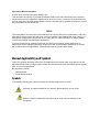
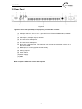
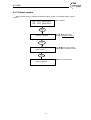
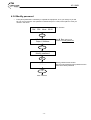
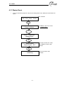
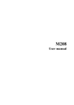
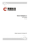
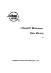
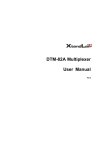
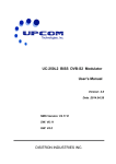
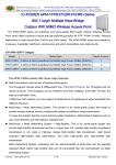
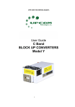
TRANSPORT STREAM MULTIPLEXER User Manual www.upcom.com Operations Manual UC-MX16 © 2007-2010 UPCOM TECHNOLOGIES, INC This document is property of UPCOM TECHNOLOGIES, INC and is delivered on the express condition that it not be disclosed, reproduced in whole or in part, or used for the manufacture for anyone other than UPCOM without written consent, and that right is granted to disclose or so use any information on said document. Notice The information in this document was believed to be correct at the time of publication, and every effort was made to ensure that the most current information was shipped with each machine. If subsequent modifications were made to your unit, and you need information on these, please contact the UPCOM documentation department. If you have technical or editorial comments concerning this manual, please write them on photocopies of the relevant pages and send them to the documentation department or contact the Customer Service Department. This assistance will be greatly appreciated Manual Applicability and Symbols This is the general operating manual for UPCOM Receivers Please make sure that the correct manual is being used by verifying part number and serial number with UPCOM technical support team or your local distributor. Be prepared to furnish: Serial Number Exact Model Number Symbols The following warning and caution symbols are used throughout this manual: Warning: A hazard exists that may result in personal injury or loss of life. Caution: Failure to follow the procedures given may result in damage to the equipment. WARNING This equipment operates at potentially lethal voltages. Only trained, qualified personnel should operate, maintain, or service it. Only technicians thoroughly familiar with the equipment must perform Service work. This equipment is rated for 85 to 265V. Proper power cords should be used for the country where the equipment will be operated. Power consumption should not exceed 50W. The UC-16MX should not be operated where the unit is exposed to extremes of temperature outside the ambient range, ( 0ºC to +45ºC ), precipitation, condensation or humid atmospheres above 75%. This equipment should not be operated around excessive dust, vibration, flammable gases, corrosive or explosive atmospheres. CONTENT 1. Before Getting Started............................................................................................................. 1 2.Introduction ................................................................................................................................ 2 2.1 Working principle.............................................................................................................................2 2.2 Function................................................................................................................................................3 2.3 Technique parameter ......................................................................................................................3 2.4 Use surrounding ................................................................................................................................3 3 Structure....................................................................................................................................... 4 3.1 Front Panel & Dimensions .............................................................................................................4 3.2 Rear Panel............................................................................................................................................5 4 Operation...................................................................................................................................... 6 4.1 Front Panel............................................................................................................................................6 4.2 UC-16MX Operation Flow ...............................................................................................................6 4.3 Menu Structure ..................................................................................................................................7 4.3.1 Setting the network address ....................................................................................................................9 4.3.3 Output number............................................................................................................................................ 11 4.3.4 Test mode...................................................................................................................................................... 12 4.3.5 Keyboard Lock ............................................................................................................................................ 13 4.3.6 Modify password........................................................................................................................................ 14 4.3.7 Master Reset................................................................................................................................................. 15 4.3.8 Version Info .................................................................................................................................................. 16 Appendix A. Alarm information ............................................................................................ 17 Appendix B. Noun Abbreviations.......................................................................................... 18 UC-16MX UC-16MX Transport Stream Multiplexer 1. Before Getting Started If you need help UPCOM and its distributors stand by every product sold. If you need help please contact your local distributor or UPCOM directly at: +1.408.329.4158 or by e-mail: [email protected] Manual Updates From time to time, new versions of software may require slight changes to the material presented in this document. Check inside the back cover for supplementary pages that may have been added to keep the manual up to date Unpacking and Inspection Before installing the equipment. Please check the box for integrity. After unpacking, look for any missing items or damage to the equipment. If there is damage, please contact customer support immediately. Do not proceed installing the equipment if there is visible or perceived physical damage. Warranty and RMA UPCOM guarantees this equipment against defects in material and workmanship for a period of 3 years from date of shipment. During this period UPCOM will repair or replace products that are under warranty. For all equipment under warranty the owner is responsible for freight to UPCOM and all related customs, tariffs, insurance, etc. UPCOM is responsible for the freight of the equipment from the factory to the owner under the same method the equipment was returned to UPCOM. Equipment shipped back to UPCOM without a previously accepted RMA will be returned to owner at owner’s expense. The warranty does not cover: products with defaced serial number, damage during shipping, damage caused by lightning, power surge or installation services. -1- UC-16MX 2.Introduction The UC-16MX is a DVB Standard Transport Stream Multiplexer supports real-time video stream multiplexing and re-multiplexing. The UC-16MX can handle 16 inport ASI SPTS or MPTS and send the out through 1 or two MPTS streams. It is compatible with the ISO/IEC-13818 standard with DVB ASI output interface. 2.1 Working principle [Principle figure] Figure2-1 [Working principle explanation] (1) The multiplexer supports 16 MPEG-2 SPTS or MPTS inputs and two MPEG-2 transport stream (MPTS) outputs. It filters out the empty packets or the unneeded packets, and changes the PID (packet identity). (2) Obtains the PSI (Program Specific Information) and SI (Service Information) and integrates them with local data. (3) The UC-16MX can connect with a network management software through TCP/IP protocol. -2- UC-16MX 2.2 Function Multiplexing to SPTS (single program transport streams) or multiplexing to MPTS (multi program transport streams), MPTS supports all-chosen or part-chosen. Supports two different outport. Low time delay. The delay for MPEG-2 Video program is less than 100ms. Providing PCR check Supports DVB data broadcast. Supports remote upgrade of the software. Real time monitor input status. Port PID monitor function, you can customize monitoring time and port. 2.3 Technique parameter PCR: < 100 ns Input interface: ASI Interface, BNC Input interface impedance: 75Ω Input interface bit rate(max): 180Mbps Input select PID num(max): 120 Input program num(max): 100 Input packet length: 188or 204byte Output interface : ASI Interface, BNC Output interface impedance: 75Ω Output packed length: 188 or204byte Total output rate(max): 180Mbps Power supply: 220VAC±10%,50Hz Power: 30W Weight: 4Kg Dimension: 450*430*44(deep*wide*high)mm 2.4 Use surrounding Working temperature: 0~45 Working humidity: 5~80% Storage temperature: -20~70 Storage humidity: 5~90% -3- UC-16MX 3 Structure 3.1 Front Panel & Dimensions Each equipment is designed for 1U(44mm)space, machine dimensions of equipment is shown as figure3-1. Figure 3-1 -4- UC-16MX 3.2 Rear Panel Figure3-2 Figure3-2 shows rear-panel map of equipment, port describe is shown: (1) ASI input channel(from1 to 16), input SPTS or MPTS with DVB standard, 75ΩBNC. (2) ASI output 1, multiplex output, 75ΩBNC. (3) ASI output 2, multiplex output, 75ΩBNC. (4) The same as to ASI output 2. (5) The same as to ASI output1. (6) RJ-45 port, network control. The customer can manage the multiplexer via any PC in the LAN or WAN. (7) RS232 port, it is used upgrade and test locally. (8) ASI ring outport. (9) Power switch. (10)Power supply. (11)GND. Note: output1 is different or same with output 2 -5- UC-16MX 4 Operation 4.1 Front Panel Channel indicator lights OK key Display screen Power light Select keys MENU key Figure 4-1 Power:power supply work indicator light, when green the system is normal. channel indicator light:Display channel status. These status is shown as appendix A Display screen:Display the system state and menu setting. select key: , key is used to switch up/down menu and add/decrease number, key is used to change numbers. MENU key:enter or exit operation. OK key:make sure the operation. 4.2 UC-16MX Operation Flow Step First Second Third Fourth Fifth Setting network address Initialization Initialization Logon Reading information Program multiplexing Logon Reading information Program multiplexing Logon Reading information Modify parameters Logon Reading information Appliance Installation Change input port transport streams Change output program parameters Status monitor Table 4-1 UC-16MX basic operation flow -6- UC-16MX 4.3 Menu Structure Figure 4-2 -7- UC-16MX Main interface shows the multiplexer running state 01# 02# • • • p03 p04 bitrat000.0 bitrat000.0 01#, 02#: Outport number. p03, p04:Output program number Bitrat000.0: Outport real time output effective bitrate For example:01# p03 bitrat015.0, means outport 1 have three programs and output bitrate is 15Mbps output1 number:Modify output1 number output2 number:Modify output2 number Network address:Setting network IP address Version info:Display equipment version information Master reset:Return to original parameters Test mode:It is a kind of work mode Keyboard lock:Setting the keyboard lock Modify password:Setting unlock password -8- UC-16MX 4.3.1 Setting the network address Modify the multiplexer IP settings to define IP address/subnet mask/gateway. 01# 02# P03 P03 bitrat 000.0 Main interface bitrat 000.0 MEN U M216 Multiplexer Output1 mumber Use key then move the cursor to network address M216 multiplexer Network address OK Ip Address 192.168.001.210 Use key to move cursor, Use key to modify number OK Subnet Mask 255.255.255.000 Use key to move cursor, Use key to modify number. OK Gateway 192.168.001.001 Use key to move cursor, use key to modify number. OK Saving network address Save the network IP address Wait please -9- UC-16MX 4.3.2 Initialization • The initialization of multiplexer deletes some Parameters of the configuration • The initialization of multiplexer is usually used during the first installation, when the input streams must be changed or when the work status is abnormal. 1、 Click” MENU”, enter into main menu. UC-16 multiplexer Output1 number 2、 Click key to move ‘master reset’. UC-16 multiplexer Master Reset 3、Click ‘OK’ key to enter the following figure. Mater Reset Master Reset OK? 4、Click “OK” key to finish initialization, the interface is shown as following figure. UC-16 Multiplexer initializing - 10 - UC-16MX 4.3.3 Output number Setting Output number modifies multiplexer outport number, for example setting output1 number 01# 02# P03 P04 bitrat 000.0 bitrat 000.0 Main interface MEN U UC-16 multiplexer Output1 Number Use key then move Cursor to output1 number OK Output1 number New number:_ _ Use key to move cursor, Use key to modify number. OK UC-16 multiplexer Output1 Number - 11 - Return to main interface UC-16MX 4.3.4 Test mode Note:When setting test mode, input port will select a program to send to outport and output, until you turn on the equipment again to return to original work mode. 01# 02# P03 P04 bitrat 000.0 bitrat 000.0 Main interface MENU UC-16 multiplexer Output1 Number Use key then move cursor to enter test mode UC-16 multiplexer Enter Test Mode OK Enter Test Enter Test Mode Mode OK? Click”MENU”key to exit, click”OK”key to make sure setting OK UC-16 multiplexer Test mode running Display test mode running When the equipment is in test mode the front panel keys can not be operated, the equipment returns to its normal working mode after you power cycle. - 12 - UC-16MX 4.3.5 Keyboard Lock Make sure operate safely by Keyboard lock 01# 02# bitrat000.0 Main interface bitrat000.0 p03 p04 MEN U UC-16 multiplexer Output1 Number Use key then move Cursor to Keyboard Lock Press UC-16 multiplexer Keyboard Lock OK Keyboard Lock Keyboard Lock OK? Click “ok” key,make sure to lock front panel OK Main interface When the front panel is locked the unlock password would be needed to operate the equipment. Original unlock password is , if you need to modify the unlock password, please look procedure ahead. - 13 - UC-16MX 4.3.6 Modify password • Front-panel password is necessary to operate the equipment; once you change it you will be only one to know the new password. Please keep it on a safe, known place in case you need it in the future. 01# 02# P03 P06 bitrat 00.00 bitrat 00.00 Main interface MEN U UC-16 multiplexer Output1 Number Use key then move cursor to modify password UC-16 multiplexer Modify password OK Modify password -------- OK Main interface - 14 - Modify password:use key to modify password,Input password is the same with check password UC-16MX 4.3.7 Master Reset • Once you reset the equipment, all previous settings will be lost. Please be careful with this option. 01# 02# P03 P04 bitrat 00.00 bitrat 00.00 Main interface MEN U M216 multiplexer Output1 Number Use key and move cursor to(master reset) M216 multiplexer Master Reset OK Master Reset Master Reset OK? Click’OK’ to make sure ‘reset’, Click ‘MENU’ to return main interface OK M216 multiplexer Initializing - 15 - Finish the master reset operation UC-16MX 4.3.8 Version Info Version info display the M216 version status information 01# 02# p03 p04 bitrat bitrat Main interface MENU UC-16 multiplexer Output1 number Use key and move cursor to(version info) UC-16 multiplexer Version Info OK Version infor 1.0 Menu Main interface - 16 - Display version information, click”menu”to return interface UC-16MX Appendix A. Alarm information Indicator light states Green light shine Green light twinkle Red light shine Light dark Input channels states Input information locked, channels port opened Input information but channels port unopened Input bitrate overflow or input port opened but no signal input No input signal or open input port - 17 - UC-16MX Appendix B. Noun Abbreviations A ASI: Asynchronous serial interface B BAT: Bouquet Association Table C CAT: Condition Access Table M MPTS: Multiple Programs Transport Stream N NIT: Net work Information Table P Program Association Table PAT: PCR: Program Clock Reference PID: Packet Identifier PMT: Program Map Table PSI: Program Specific Information S Service Description Table SDT: SI: Service Information SPTS: Single Program Transport Stream T Time and Date Table TDT: TS: Transport_Stream - 18 - Upcom Technologies, Inc. San José, California. Copyright 2007-2010 Tel: +1.408.329.4158 Fax: +1.408.329.4159 website:www.upcom.com