1
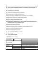
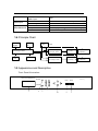
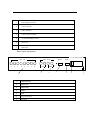
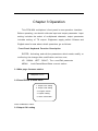
DTM-82A Multiplexer
User Manual
V2.0
Chapter 1 Product Outline
1.1 Outline
DTM-82A multiplexer is a digital broadcasting TV system TS stream
re-multiplexer. DTM-82A multiplexer combines several single-programs or multipleprograms,
which are compressed, coded, and multiplexed according to
customer request by head-end, into single transport stream. Besides, it is also
able to interpolate EPG (Electronic Program Guide), CA (Conditional Access) and
digital broadcasting etc. Maximally, it can synchronal multiplex 8 route input code
streams, and support ASI interface. The code rate of input code stream is
maximally up to 270Mbps, while code rate of four separate outputs code stream is
maximally up to 155Mbps. Through auxiliary data input channel, Its dimension is
standard 1U case. By watching the LCD display on the front panel, user can finish
the setting of auto-running of this device.
1.2 Features
◆Complying ISO13818 standard.
◆Multiplexing SPTS and MPTS code stream.
◆Support 8 single signal input
◆2 separate output
◆support scrambled signal transmit free
◆Draw out PSI/SI from any channel
◆Can point 256 PID in each channel
◆Input at most 30 program each channel, and 29 output
◆redefine PAT,PMT and other SI/PSI
◆Support PCR adjusting and PID re-reflection
◆ Have the function of insert and reflection of SDT/NIT
◆ Able to connect independent scrambler for scrambling to specified program or
service.
◆ Generating SPI/SI information
◆ Support PCR adjusting and PID re-reflection
◆ out put data rate 0-155Mbps,188 byte format
◆ Each input support 270Mbps data rate, total 8 input rate is 576Mbps
◆ High precision PCR revise, usually holding 20-60ns
◆ MPEG2 program delay less than 100μs
◆ PID filtration/PID redefine function. User can delete, add, revise program even
the program name, PID or serials No. easily.
◆ Chinese and English LCD display
◆ Ethernet interface10/100M, long-distance control multiplexer via PC
◆ Have the function of parameter memory
◆ Have the function of PSI auto-built.
◆ High reliability design, stable in running
◆ Alarm display
◆ Support network upgrade
1.3 Performance Index
Input Interface
ASI
Re-multiplexing
Output
Interface
PID
8Routes Standard ASI Interfaces
Maximum 270Mbps per route
Re-multiplexing MPEG-2 stream
PID re-reflection
PCR reset
Automatically generating PSI/SI table
ASI
4 routes(2 gyoups separate output)
Output PID range
Random PID
transparent transport
0000-1FFF
Random PID
possbile
transparent
transport
Data input
Miscellaneous
Max PID number for
each input
Format
Ethernet port
Dimension
256
Auto identification,188/204byte,encoding
10/100M
44mmx482mmx330mm
0-45℃ (Operating) ; -20-80℃ (Storage)
110~220VAC±10%,50/60Hz,2 5W
Temperature
Power
1.4 Principle Chart
Ethernet
PS232/4
module
85
TS Input
module
8 input
PID filtrate, mapped
CH analyse, select
Controlling module
LCD
Keyboard
PID filtrate, mapped
CH analyse, select
TS adjusting,
controlling
Output module
multiplexing
TS adjusting,
controlling
Output module
multiplexing
1.5 Appearance and Description
Front Panel Illustration:
Digital Video
DTM-82A Multiplexer
Broadcas ting
Power
Enter
Menu
Alarm
1
2
3
4
6
7
.
1
LCD Disp lay Interface
2
Power Indic ator
3
A larm Ind ic ator
4
Input CH lock indic ato r
5
Up /Down/Left/Righ t Arrow
6
Enter k ey
7
Menu Key
Rear Panel Illustration
AC110-220V/50/60Hz
ASI
IN
ASI
OUT
RS232
RJ45
0
1
1
2
3
4
5
6
7
8
CH1
2
1
1
8 ASI Input CH
2
Output CH1
3
Output CH2
4
RS232
5
RJ45
6
AC Power Sock et
7
G round ing
CH2
3
4
5
6
7
Chapter 2 Installation Guide
2.1 Acquisition Check
When users open the package of the device, it is necessary to check
items according to packing list. Normally it should include the following
items:
J XDH-6102
multiplexer
1
Us er’s Manual
1
ASI digital signal input and output wire
8
AC Input Power Cord
1
If any item is missing or mis match with the list above, please contact
local dealer.
2.2 Installation Preparation
When users install devic e, pleas e follow the below steps. The details of
installation will be described at the rest part of this chapter. Users can also
refer rear panel chart during the ins tallation.
The main content of this chapter including:
□
Checking
the
possible
device
missing
or
damage
during
the
transportation
□
Preparing relevant environment for installation
□
Installing Encoder DTM-82A Multiplexer
□
Connecting signal wires
2.2.1 Device’s Installation Flow Chart Illustrated as following:
Acquisition
Check
Fixing
Device
Connecting
Grouding
Wire and
Power Cord
Connecting
Signal W ire
Setting
Parameter
Running
Device
2.2.2 Environment Requirement
It e m
Requ i re men t
W hen u se r in s ta ll m ac h in e fr ame a rr ay in on e mac hin e ha ll, t h e
M ach ine
h al l
d is ta n c e b etw een 2 row o f m ac h in e f ra m es sh ou ld be 1 .2 ~1 .5m
sp ac e
and th e d istan c e t o w all s h o u ld be no less t h an 0 .8m。
Electric Isolation, Dust Free
Volume resistivity of ground anti-static material:1(107~1(1010(,Grounding
M ach in e h all f lo or
current limiting resistance: 1M(。
Floor bearing should be greater than 450Kg/m2。
Environment
5~40(C sustainable ,0~45(C short time,
temperature
installing air-conditioning is recommended
Relative temperature
20%~80% sustainable
Pressure
86~105KPa。
10%~90% short time
Installing rubber strip for sealing door-gaps and dual level glasses for
Door & window
window
Wall
It can be covered with wallpaper, or brightness less paint.
Fire protection
Fire alarm system and extinguisher
Requiring device power, air-conditioning power and lighting power are
Power
independent to each other. Device power requires AC power 220V
50Hz,50W Please carefully check before running.
2.2.3 Grounding Requirement
□
All function modules’ good grounding designs are the base of reliability and
stability of device. Also, they are the most important guarantee of lightning
arresting and interference rejection. Therefore, system must follow this rule.
□
Coaxial cable’s outer conductor and isolation layer should keep sound electric
conducting with the metal housing of device.
□
Grounding conductor must adopt copper conductor in order to reduce high
frequency impedance, and the grounding wire must be as thick and short as
possible.
□
The 2 terminals of grounding wire must make sure for well electric conducting,
and process for antirust.
□
It is prohibited that users use other devices as part of grounding wire’s electric
circuit
□
The section of the conjunction between grounding wire and device’s frame
should be equal or greater than 25mm2
2.2.4 Frame Grounding
All the machine frames should connect to protective copper strip. The
grounding wire should be as short as possible and avoid circling. The section of
the conjunction between grounding wire and grounding strip should be equal or
greater than 25mm2。
2.2.5 Device Grounding
Connecting the dev ice’s grounding rod to frame’s grounding strip with
copper wire.
2.3 Wire’s Connection
The power supply outlet is located at the left of rear panel, and the
power s witch is just above it. The protective grounding wire connective
sc rew is loc ated at the down-left side of power supply outlet
Connecting Power Cord
User can insert one end into power supply outlet, while insert the
other end to AC power.
Connecting Grounding Wire
When the device solely connects to protectiv e ground, it should
adopt independent way, say, share the same ground with other devices.
When the device adopts united way, the grounding resistance should be
smaller than 1Ω
FCaution:
Before connecting power cord to Encoder, user should set the power switch to “OFF”.
2.4 Signal Wire Connection
The signal connections inc lude the connection of input signal wire
and the connection of output signal wire. The signal connection wire are
both ASI.
2.4.1 ASI Input Connection
User can find ASI IN1-IN8 input port on the Equipment, according to connector mark
described in the rear panel illustration, and then, connecting the Q9 coaxial cable, one end to
the ASI IN1-8 and the other end to the Encoder’s or other equipment ASI output port.
2.4.2 ASI Output Port Connection
User can find ASI output port on the Equipment, according to connector mark described
in the rear panel illustration, and then, connecting the ASI cable (in the accessories), one end
to the DTM-82A multiplexer’s ASI output port and the other end to the scrambler’s or
Modulator’s input port. multiplexer’s ASI output port and its connected ASI cable connector
illustrated as follow:
Chapter 3 Operation
This DTM-82A multiplexer ’s front panel is user operation interface.
Before operating, we should colloc ate input and output parameter. Input
setting includes the select of multiplexed channels, output parameter
includes setting of TS output. Equipment supply perfect Chinese and
English menu for user select, detail operations go as follows:
Front Panel Keyboard Function Description
ENTER:Activating and edit the parameters whic h needs modify, or
confirming the change after modification and turn over;
UP、DOWN、LEFT、RIGHT:Turn over/Edit parameter
MENU: Lock/Cancel/Save/Show current station
3.1 Main page: Common station
Multiplexer V1.81
3.2 Press ENTER to main menu
1. Output CH1 setting
2. Output CH2 setting
3. Program search
4. System setting
5. Alarm Information
Press UP/DOWN to select
3.3 Output CH1 setting
When user select this setting, the system will show as follows:
1.1 Port 01 Setting
1.2 Port 02 Setting
1.3 Port 03 Setting
1.4 Port 04 Setting
1.5 Port 05 Setting
1.6 Port 06 Setting
1.7 Port 07 Setting
1.8 Port 08 Setting
1.9 Output Rate
1.10 Trans stream ID
1.11ORG Network ID
1.12 Mux confirm
1.13 Mux No.
User can finish the select of program or parameter at each input port
3.4 Port 01 Setting
When user select this setting, the system will show as follows:
1.1.1 Port 01 Number
1.1.2 Port 01 Mux
If want to edit the TS of other ports, select the related port will be ok
3.5 Output Rate
When user select this setting, the system will show as follows:
1.9 Output Rate
100000kbps
3.6 Trans Stream ID
When user select this setting, the system will show as follows:
1.10 Trans Stream_ID
0x0000
3.7 ORG network ID
When user select this setting, the system will show as follows:
1.11 Original_network_ID
0x0000
3.8 Mux Comfirm
When user select this setting, the system will show as follows:
1.12Yes
No
Enter
Menu
3.9 Mux Number
When user select this setting, the system will show as follows:
1.13 Output 01 Mux Sum:
XX
3.10 Output CH2 Setting
The same as the setting of CH1
3.11 Program search
When user select this setting, the system will show as follows:
3.1 Auto All Search
3.2 Port Search
3.12 System setting
When user select this setting, the system will show as follows:
4.1 Network Setting
4.2 Factory config
4.3 Version Number
3.13 Network Setting
When user select this setting, the system will show as follows:
IP Address:
101.101.101.100
Subnet Mask:
255.255.255.000
GateWay:
101.101.101.004
MAC Address:
602020070505
3.14 Factory config
When user select this setting, the system will show as follows:
Press Enter
Renew
Press Menu
Exit
3.15 Version Number
When user select this setting, the system will show as follows:
Hardware:V1.0
Software:V1.0
3.16 Language select
When user select this setting, the system will show as follows:
* 中文
English
Press UP/DOWN to select language, the “* ” direct the selected one. Default
is Chinese version.
3.17 Alarm Information
When user select this setting, the system will show as follows:
No Alarm
Finish all the setting, the multiplexer can operate normally.