1
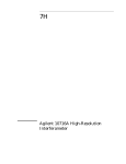
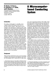
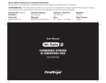
S6/S7
User Manual
Quested Monitoring Systems Ltd.,
Units 6-8 Kingsgate,
Heathpark Industrial Estate,
HONITON,
Devon EX14 1YG
England
Tel: ++(0)1404.41500 Fax: ++(0)1404.44660
www.quested.com
CONTENTS
1
Introduction
3
2
Safety Considerations
3
2.1
2.2
3
4
3
Unpacking
4
4
Installation
4
4.1
4.2
4.3
4.4
4.5
4
5
5
6
7
4.6
5
6
7
1
General
Hearing damage
Positioning
Grill
Aligning the speakers
Wall mounting
Electrical Connection
4.5.1 Safety Earthing
4.5.2 Voltage Setting
4.5.3 Fuse Setting
Audio connections
7
7
8
8
Operational Considerations
10
5.1
5.2
5.3
5.4
5.5
5.6
10
10
10
10
10
Mains On-Off Switching
Thermal
Front panel controls
Signal level
Contour selectors
Front/rear panel detail
10
S6 Technical Information
10
6.1
6.2
6.3
Rear Panel Detail
Specification
Line Drawing
11
11
11
S7 Technical Information
12
7.1
7.2
7.3
12
12
13
Rear Panel Detail
Specification
Line Drawing
8
Guarantee
14
9
Appendix
15
9.1
9.2
9.3
15
15
15
Accessories
Spares
Driver replacement
INTRODUCTION
2
Thank you for purchasing this Quested monitor and you can be certain that you have purchased one of
the finest monitors in the world. If you take time and care in positioning and aligning the system, you
will appreciate why Quested monitors have a reputation for faithful reproduction covering the entire
audible spectrum. They are professional monitors, and therefore are not designed to flatter but
faithfully reproduce. Please take care to maintain the system and it will give you many years of
service.
You will also be assured the best possible performance and long term reliability of your system.
Please read this manual, which we have kept as concise as possible, it really will help you and covers
important safety considerations.
The S6 and S7 are self-powered, 2-way active monitors. Their integral electronics make them an ideal
choice where space is at a premium and the magnetic shielding, which is a standard feature of these
units, allows them to be used in close proximity to TV and computer monitors. Typical applications
include near-field monitoring for recording/mixing, post production suites, broadcast and surround
sound. The high power output enables the monitors to be used where high monitoring levels are
required and in applications such as location work, when powerful, yet portable monitors are essential.
The compact size allows for ease of placement of three or more units for LCR and multi-channel
applications.
Although the bandwidths of the S6 and S7 are adequate for most situations, the low end performance
can be further extended by combining it with an SB series sub bass. The two products make an ideal
combination and extend the frequency response down to 20 Hz.
The SB.1 s eri es is the model to choose if setting up a multi-channel system. This model has a bass
management controller that will correctly process the low frequency information from the LCR and
surround channels, as well as handle the LFE channel output. The SB.1 s eries is suitable for all
surround systems 5.1, 6.1, 7.1, Dolby, DTS etc. and provides a range of facilities to aid tuning of a
multi-channel system to the room in which it is being used.
2
Safety Considerations
2.1 General
Before proceeding to connect your Quested monitor to the AC power supply, please read the following
safety information:-
CAUTION:
RISK OF ELECTRICAL SH O CK. REFER SERVICING TO QUALIFIED
PERSONNEL.
THE POWER C ORD MUST ALWAYS BE REMOVED BEFORE THE AMPLIFIER
IS
DISMANTLED.
WARNING: TO REDUCE THE RISK OF FIRE OR ELECTRICAL SHO CK, DO N OT EXPOSE
THIS
APPLIANCE TO RAIN OR MOISTURE.
WARNING: THIS APPLIANCE MUST BE EARTHED.
The cores in the supplied mains lead are colour coded in accordance with the following code:
Green and Yellow:
Blue:
Brown:
Earth
Neutral
Live
As the colours of these wires may not correspond with the coloured markings identifying the terminals
in your plug, proceed as follows:
The wire, which is coloured green and yellow, must be connected to the terminal in the
plug, which is marked with the letter ‘E’ or by the earth symbol, or coloured green and
3
yellow.
The wire, which is coloured blue, must be connected to the terminal in the plug which is
marked with the letter ‘N’ or coloured black.
The wire, which is coloured brown, must be connected to the terminal in the plug which is
marked with the letter ‘L’ or coloured red.
NOTE: For certain countries the power cord will be supplied with an integral moulded plug to satisfy
national safety standards.
CAUTION:
THE REAR PANEL OF THE S6 and S7 IS PART OF THE HEAT SINKING
ARRANGEMENTS
CAUTION:
AND WILL BECOME WARM.
THIS UNIT IS FULLY SHIELDED, BUT IT DOES C ONTAIN MAGNETIC
C OMPONENTS,
WHICH CAN AFFECT ADJACENT SENSITIVE EQUIPMENT.
2.2 Heari ng damage
This equipment can deliver sound pressure levels in excess of 100 dB. At this level permanent hearing
damage can occur and exposure to this level of sound, even for relatively short periods (see table
below), can be harmful. Of equal importance to the maximum level of sound is the exposure to high
levels of sound for extended periods. There are no internationally agreed limits and different countries
have different limits, which are measured in differing ways. IT IS THEREFORE IMPORTANT THAT
THE
USER ESTABLISHES THE RECOMMENDED, AND IN SOME TERRITORIES, LEGAL LIMITS
WHICH ARE IN
PLACE.
As a guide the table below shows the levels that are acceptable in the majority of Western Europe, the
US and Canada.
dB(A)
Listening time per day
90
8 hours
95
2.4 hours
100
40 minutes
105
15 minutes
110
5 minutes
115 and over
Not at all
It is also important to note that the effect of exposure to sound is cumulative. Having listened to
sound, for example for 15 minutes at 105 dB, then further exposure to noise levels above 80 dB
should be avoided until the next day.
3
Unpacking
This Quested product has been carefully manufactured, tested and packed to ensure that it arrives in
a flawless condition. The component parts of the packing have been thoughtfully designed to offer
sufficient protection during transportation, yet remain fully recyclable and should be retained for
future use. Also included in a separate bag will be the appropriate power cord for your country.
4
Installation
4.1 Positioning
The S6 is designed to be mounted vertically but may be turned on its side into a position where the
bass driver and soft dome are mounted horizontally.
The S7 is designed to be mounted vertically and will also function if turned on its side. However it
should be noted that there will be a reduction in its thermal performance of up to 25% if positioned
4
horizontally. (See section 5.2 Thermal for implications.)
The S6 and S7 are tolerant of a variety of mounting positions including stand, shelf, table or wall
mounting. Which ever way is chosen, the support should be rigid and must not vibrate when the
monitor is driven. Vibrations will result in lack of low frequency definition. The optimum location for
the
monitors within a room is best determined by experimenting and placing the speaker in a variety of
positions. The shape of the room, normal listening position and room treatment will all have an effect
on determining the speakers’ final positioning. It is possible to soffit mount the S6 and S7, however it
is essential that adequate air flow is provided behind the soffit to ensure the amplifier is adequately
cooled.
4.2 Grill
The S6 and S7 have the option of a cloth grill, which will offer some protection to the tweeter and
bass driver. It is not designed to protect the speakers during transit and it is recommended that the
original packing should be retained for this purpose. Like all types of speaker protection or covering,
the grill makes a small difference to the HF acoustic performance, which, for the majority of users, will
not be
noticeable.
4.3 Aligni ng Speakers
The speakers should be positioned so that the axis (an imaginary line drawn from the acoustic centre
of the left and right monitor — see line drawing on page 13 of this manual) should cross between 0.5
and 1 metre behind the engineer’s ear position, for the following reasons:a) To obtain the most accurate imaging, both front to rear and side to side and also to
achieve as large a listening area as possible so that the engineer can move and
operate the console without perceiving a change in character of the monitors.
b) To enable listening for long periods of time without suffering strain or fatigue.
For details of positioni ng and aligning the speakers for multi-channel systems s uch as 5.1,
7.1 etc.
see the detail ed instructions contained in the SB.1 s eries sub-woofer us er manual.
Below is a sketch showing positioning of speakers. The S6 and S7 are suitable for a wide variety of
applications, therefore the distance apart may range from less than 1 m to 4 m. However, the
principle of the triangle and the axis of the 2 speakers crossing behind the listening position remains.
5
The height and angle of mounting the speaker is equally as important. The correct height and angle
should result in the axis being at ear level when the engineer is sitting in his normal position at the
console.
4.4 Wal l Mounti ng/Stand Mounting
The S6 and S7 have built in mounting points that are located on the base of the cabinet and are
suitable for Omnimount™ brackets (S6 uses the 20.5 series:- 20.5 WB or 20.5 CB or ST; S7 uses the
60.0 series:- 60.0 WB or 60.0 CB or ST) and also Quested stands. The position of the mounting points
6
are indicated on the line drawing on page 13 of this manual. BRACKET MOUNTING OF ANY
HEAVY SPEAKER INVOLVES SERIOUS SAFETY ISSUES. IT IS IMPORTANT TO FOLLOW
THESE GUIDELINES
CAREFULLY AND TO READ THE INSTRUCTIONS THAT ACC OMPANY THE MOUNTING
HARDWARE.
When fixing the mounting plate to the loudspeaker:
•
The bolt length must always penetrate at least 20 mm into the cabinet base. For the
recommended Omnimount ™ plate, the minimum bolt length is 25 mm.
•
Always use locking washers and thread lock compound.
•
Always use all of the M6 bolts.
•
Because the cabinet is a source of vibration, the bolts must be properly tightened, but
caution must be exercised as over-tightening could damage the case. Always tighten the
bolts a little at a time in order to spread the stress over the area of the mounting plate. If a
torque wrench is available the recommended final torque is 6 Nm (4 lbf-feet). A 200 mm (8”)
spanner will achieve the appropriate torque without needing hard work.
•
If the Omnimount™ bracket is being used and the cabinet angled downwards, orient the
mounting plate so that the ball and socket are closer to the FRONT of the cabinet. BE
CAREFUL
WHEN POINTING THE S6 OR S7 AT SHARP ANGLES DO WN (MORE THAN 30°) AS
THE CENTRE OF GRAVITY IS MOVED FORWARD CAUSING HIGH BENDING
TORQUE AT THE CLAMP, PLACING EXCESSIVE LOAD ON THE BALL AND CLAMP
OF THE OMNIMOUNT™ AND THE CABINET FIXING
POINTS. (IF IN DOUBT ASK.)
•
The cabinet may safely be suspended upside down from a ceiling or top mounted bracket,
but the mounting plate should be oriented so that the ball and socket are closer to the REAR of
the cabinet.
IT IS THE RESPONSIBILITY OF THE OWNER TO ENSURE THAT THE BUILDING
STRUCTURE AND
WALL/CEILING FIXTURES ARE STRONG ENOUGH TO SAFELY BEAR THE IMPOSED
LOAD.
The mounting plate holes are sealed by M6 x 16 mm nylon countersunk machine screws. These will
need to be removed before the cabinet can be screwed onto the mounting bracket. The S6 has 3 fixing
holes, 2 of which are for the Omnimount™ and 2 for the Quested stand, with 1 being common to
both.
It is important that only the relevant bolts are removed as the holes that are not used will need to be
sealed. THESE NYLON S CREWS SH OULD NOT BE USED TO MOUNT THE CABINET, THEY
ARE NOT OF
SUFFICIENT STRENGTH. A STEEL MACHINE SCREW OF AT LEAST 25 mm IN LENGTH
SH OULD BE USED
FOR THIS PURPOSE. If the S6/ S7 is subsequently removed from the bracket, the mounting holes
will need to be re-sealed using the nylon screws or some other suitable sealant.
4.5 Electrical Connection
4.5.1
Safety Earthing
This product has been designed to comply with international safety standards. It is
essential that the green/yellow core of the mains cable, or the ground pin of a 3-pin
moulded plug, is connected to the electrical installations safety earth or ground. It is
internally connected to all exposed metal surfaces and it is essential for personal
safety as well as proper operation of the product. Th e audio signal in-put is electronically
balanced and does not need the disconnection of any safety earth for the avoidance of
hum loops.
7
4.5.2
Voltage Setting
The set voltage is indicated on the rear panel of the unit, adjacent to the IEC inlet connector.
At this setting there is an acceptable tolerance over which the performance of the unit will
continue to meet its specifications. (See power requirements on page 12 of his manual.) For
the 230V setting this is 160V to 255V and for the 115V setting it is 80V to 127V. If the unit is
connected to voltages in excess of its maximum, damage is likely to occur which may not be
recoverable from without qualified service attention.
To change the set voltage, the amp must be removed from the speaker. The power and
signal cables must be disconnected before continuing. Remove the 4 x M4 x 12 socket screws
from the four corners of the amp. Carefully remove the back-panel and you will see 6 wires
connecting to the amplifier with various connectors. Note the orientation and position of
them all and then disconnect. If you look at the amplifier, you will see a PCB mounted on the
rear of the IEC inlet connector. Marked on the PCB you will see the 2 terminals marked with
the set voltage (see diagram). Locate and move the connectors to the other voltage tap, noting
that the coloured wires correspond with the printing on the PCB. Reconnect the wires from the
cabinet to the amplifier and replace the amplifier using the 4 bolts. You must now change the
fuse located in the IEC inlet socket for the correct one as indicated on the back panel. IT IS
IMPORTANT THAT YOU NOW MARK THE REAR OF THE UNIT WITH THE NEW SET
VOLTAGE.
115V Tap
230V Tap
4.5.3
Fuse Setting
It is very unlikely the fuse will fail during normal use, but should this occur the situation must
be approached with some caution. Check that the mains voltage setting is correct for your
installation supply and that the original fuse was the correct rating. (See 9.2 Spares) The fuse
may blow if the unit is subjected to mains power surges or spikes, or if the mains wiring has
any poor or faulty connections, in which case a qualified electrician should be consulted. Very
occasionally a fuse can become degraded after many years of service and simply replacing it
with a new one will restore the system.
The fuse is housed in a unit integral with the IEC inlet connector (see rear panel drawing page
of this manual). To gain access to the fuse remove the power cord and unclip the fuse carrier
using a flat blade. A spare fuse of the correct rating is also provided within the same carrier. If
none of the above is the cause of the fault it is likely that the unit has suffered an internal
component failure and will need returning to a qualified agent for servicing IF THE
REPLACEMENT FUSE SHOULD FAIL DISC ONNECT FROM THE MAINS
IMMEDIATELY AND HAVE
THE UNIT PROFESSIONALLY REPAIRED BEFORE ATTEMPTING TO USE IT.
Exploded view of small PCB viewed from above showing the voltage selection connectors with
alternative pins for the 115V and 230V settings
8
4.6 Audio connections
The audio signal input is RF filtered and electronically balanced to ensure a high level of rejection
for common mode interference signals and to give a professional connection to external equipment. It
is essential for optimal use of these specifications that a professional grade, balanced two-core
screened cable is used.
Source Balanced Pin 2 hot
In accordance with international standards, 3-pin XLR style input connectors are used, with pin
2 being designated the ‘in-phase’ or ‘hot’ terminal and pin 3, the ‘out of phase’ or ‘cold’ terminal.
Pin 1 is connected to the chassis ground and must be connected to the screen of the audio
interconnecting cable. This is necessary to ensure proper compliance with European Standards for
Electromagnetic Compatibility. Pin 1 carries no signal voltages or currents and is provided purely for
screening purposes. It should not be connected to either pin 2 or pin 3.
Source Unbalanced Pin 2 Hot
If the equipment providing the audio signal has an unbalanced output, then the interconnecting audio
cable should be wired so that the hot output of the source is connected to pin 2 of speaker input XLR
and the ground of the source connected to pin 3. The screen of the interconnecting audio cable should
be connected to pin 1 of the input connector only. There must be no connection betwee n the
ground connection of the unbalanced output and the pin 1 ground connection of the i nput
connector.
9
Source Unbalanced Pho no
If the source output is a phono socket, then the centre pin of the phono plug should be wired to pin 2
of the speaker input XLR and the outer phono casing to pin 3. The wire from pin 1 of the XLR will
not be connected to the terminals of the phono plug. Strict adherence to this will help to eliminate
ground loop hums and RF break through.
Source Unbalanced Pho no 2 Core cable
5
OPERATIONAL CONSIDERATIONS
5.1
Mains O n- Off Switching and level
On-Off switching is provided by a rocker switch on the rear panel. Intelligent circuitry ensures
noiseless power-on and power off.
5.2
Thermal
10
The output devices of the internal power amplifiers are mounted onto an internal heatsink,
which heats up and reaches temperatures well above that of ambient. The design is such that
no forced cooling is necessary, provided sufficient free space can be maintained around the
cabinet to allow the air to circulate freely. The internal circuitry monitors temperature to
maintain its safe operating area. Should this detect unsafe temperatures, output power is
reduced to protect the amplifier and the signal is ‘chopped’ and will become distorted. Once
temperatures have reached the safe operating level, normal operation will resume.
5.3
Front Panel Indicators
A dual-purpose LED is mounted behind the LOGO badge on the front of the cabinet. This will
signal green for power and red whenthe amplifiers is running 2 dB under clip. The clip
indication should be used as a guide that the amplifier is approaching clip, which should be
avoided for audible integrity.
5.4
Signal Level
Input sensitivity can be adjusted with the ten position rotary switch recessed in the rear panel
by using a flat bladed screwdriver. The control has an 18dB range in 2dB steps and accurately
sets the SPL level for a known input signal level. With the switch set at the 0dB position, 0dBu
of pink noise will produce 96dB SPL at 1 meter.
5.5
Contour Sel ectors
There are two switch groups that control the HF and LF contour settings. These can be used to
adjust for room conditions or personal preference. The nominal flat position is indicated with a
flat line. The spea ker will only operate correctly if the switches are in one of the
positions shown on the rear panel.
6 S6 TECHNICAL INFORMATION
6.1
Rear panel detail
2k10k20k
HFCOMPENSATION
(2 dB Steps)
LFCOMPENSATION
80Hz
(2 dB Steps)
S6
2 WAY ACTIVE
MONITOR
+4
+2
0
-10
-8
-12
-2
-4
+6
-6
INPUTLEVEL
dBufor96dBSPL
CAUTION
RISK OF ELECTRIC SHOCK
DISCONNECT POWER BEFORE OPENING
CAUTION
ALLOWADEQUATEVENTILATION
PANEL MAY BE HOT
CAUTION
CONTAINS MAGNETIC COMPONENTS
MAY AFFECT SUSCEPTIBLE EQUIPMENT
INPUT
Pin1[Sleeve]=Ground
Pin 2[Tip] = Hot (+)
Pin 3[Ring] = Cold (-)
POWER
MainsVoltage
MAINSIN
AC
SerialNumber
50/60Hz 80VA
VOLTAGE/FUSERATINGS
115:(85V-130V)=T3.15A
230:(170V-260V)=T2A
Designed&Manufacturedby
QUESTEDMONITORINGSYSTEMSLtdUK
6.2
Specification
Dimensions:
Weight:
Drivers:
Maximum SPL:
170(w) x 285(h) x 240(d) mm
7.5 kgs
Bass cone - 1 x 130 mm (5”)
High Frequency soft dome - 1 x 28 mm (1 ⅛”)
104 dB (c) continuous pink noise @ 1 m (116 dB (c) per pair RMS
music)
11
Frequency Response:
Connector:
Impedance:
Wiring:
Sensitivity:
Subsonic:
Ultrasonic:
Crossover:
LF EQ:
HF EQ:
75 Hz-22 kHz ± 2 dB
XLR and ¼ inch Jack combo socket
10k Ω electronically balanced with RF filters
Pin 1 ground Sleeve
Pin 2 hot
Tip
Pin 3 cold
Ring
-12 dBu to +6 dBu for 96 dB SPL @ 1 m set by 10 position rotary switch on
rear
-3dB @ 45 Hz, 24dB/oct
-3dB @ 75kHz, 4dB/oct
1k19
-2/-4 @ 82 Hz
+/- 2dB @ 10 kHz
PO WER AMPLIFIER
LF output power:
HF output power:
THD:
Hum & Noise:
> 65W RMS continuous (note 1)
> 45W RMS continuous (note 1)
< 0.03% at levels up to 1 dB below clip, 20 Hz-20 kHz. typ 0.005% @ 1kHz.
> -100 dB referred to clip
NOTE 1: The continuous rating is for a period not exceeding 5 minutes with unrestricted airflow (100
mm clearance) around the amplifier heatsinks and an ambient temperature not exceeding
30ºC.
INDICATORS
Power on:
Clip:
Front mounted green LED indicates power applied.
Red LED 2 dB before amplifier clip.
PO WER REQUIREMENTS
Voltage:
Set by internal plugs: nominal 115V or 230V @ 50-60 Hz AC
230V setting: min 160V; restricted output power: max 255V
115V setting: min 80V; restricted output power: max 127V
C ONSUMPTION
Quiescent:
Typical use:
Max:
12W
45W (average music)
90W (average music)
Note: 0 dBu = 775 mV into open circuit
12
6.3
Line Drawing
170.0
238.0
285.0
176.5
Cabinet (bottomview)
45.0
83
76,2
7
S7 TECHNICAL INFORMATION
7.1
Rear panel detail
2k10k20k
HF COMPENSATION
(2dBSteps)
S7
LF COMPENSATION
(2dBSteps)
80Hz
+4
+2
0
-2
-4
+6
-12
-6
-10
2WAYACTIVE
MONITOR
INPUTLEVEL
dBu for 96dB SPL
-8
CAUTION
INPUT
Pin1[Sleeve]=Ground
Pin2[Tip]=Hot(+)
Pin3[Ring]=Cold(-)
RISKOFELECTRICSHOCK
DISCONNECTPOWERBEFOREOPENING
CAUTION
ALLOWADEQUATEVENTILATION
PANELMAYBEHOT
CAUTION
CONTAINSMAGNETICCOMPONENTS
MAYAFFECTSUSCEPTIBLEEQUIPMENT
Mains Voltage
AC50/60Hz60VA
VOLTAGE/FUSERATINGS
Serial Number
115:(85V-130V)=T3.15A
230:(170V-260V)=T2A
POWER
Designed & Manufactured by
QUESTED MONITORINGSYSTEMSLtd UK
MAINSIN
13
7.2
Specification
Dimensions:
Weight:
Drivers:
Maximum SPL:
244(w) x 347(h) x 302(d) mm
11.7 kgs
Bass cone - 1 x 165 mm (6 ½ ”)
High Frequency soft dome - 1 x 28 mm (1 ⅛”)
115 dB (c) continuous pink noise @ 1 m (121 dB (c) per pair RMS
music)
Frequency Response:
Connector:
Impedance:
Wiring:
Sensitivity:
Subsonic:
Ultrasonic:
Crossover:
LF EQ:
HF EQ:
65 Hz-22 kHz ± 2 dB
XLR and ¼ inch Jack combo socket
10k Ω electronically balanced with RF filters
Pin 1 ground Sleeve
Pin 2 hot
Tip
Pin 3 cold
Ring
-12 dBu to +6 dBu for 96 dB SPL @ 1 m set by 10 position rotary switch on
rear
-3dB @ 30 Hz, 24dB/oct
-3dB @ 75kHz, 4dB/oct
1k19
-2/-4 @ 65 Hz
+/- 2dB @ 10 kHz
PO WER AMPLIFIER
LF output power:
HF output power:
THD:
Hum & Noise:
> 120W RMS continuous (note 1)
> 70W RMS continuous (note 1)
< 0.03% at levels up to 1 dB below clip, 20 Hz-20 kHz. typ 0.005% @ 1kHz.
> -100 dB referred to clip
NOTE 1: The continuous rating is for a period not exceeding 5 minutes with unrestricted airflow (100
mm clearance) around the amplifier heatsinks and an ambient temperature not exceeding 30ºC.
INDICATORS
Power on:
Clip:
Front mounted green LED indicates power applied.
Red LED 2 dB before amplifier clip.
PO WER REQUIREMENTS
Voltage:
Set by internal plugs: nominal 115V or 230V @ 50-60 Hz AC
230V setting: min 160V; restricted output power: max 255V
115V setting: min 80V; restricted output power: max 127V
C ONSUMPTION
Quiescent:
Typical use:
Max:
18W
75W (average music)
140W (average music)
Note: 0 dBu = 775 mV into open circuit
This product is built to conform to the requirements for CE marking.
14
7.3
Line Drawing
301,0
244,0
347,0
203.0
Cabinet(bottomview)
150,5
150,5
127
122,0
69,5
101,5
122,0
34,75
8
GUARANTEE
The S6 and S7 electronics are guaranteed for 5 years from date of purchase. All other parts are
guaranteed for 24 months. If any part of the product is found to be defective because of faulty
manufacture within these periods , Quested, through its authorised distribution network, will effect
repair or replacement, at its discretion, free of charge providing that::
a)
b)
c)
d)
e)
f)
The fault is reported to the authorised distributor.
Proof of purchase is provided.
The fault is not caused by misuse, neglect, or faulty operation by the user.
The fault is not a result of fair wear and tear.
The equipment has not been modified in any way.
The equipment has not been taken apart or tampered with in anyway other than described
in the service manual for the adjustment and replacement of user accessible items.
The guarantee does not cover:
a)
b)
c)
Damage during transit
Damage to diaphragms, cones and other speaker parts as a result of the over-driving of the
monitors or by faulty installation or connection.
Damage caused by incorrect installation or during installation caused by incorrect handling.
15
d)
9
The cost of carriage to or from the authorised repairer.
APPENDIX
9.1
Accessori es
Grill
Omnimount™ plus fixings
Quested S series stands (with unique coupling system)
9.2
Spares
Description
Part Number
S6
LS132.25 8 Ω 130 mm (5”) Loudspeaker
T W20 8 Ω shielded soft dome
Fuses T2A
Fuses T3.15A
Q01-0070
Q03-0040
L01-0022
L01-0010
S7
LS-160.25 6.5” bass driver
T W20 8 Ω shielded soft dome
Fuses T2A
Fuses T5A
9.3
Q01-0080
Q03-0040
L01-0022
L01-0024
Driver replacem ent procedure
If it is necessary to replace the bass driver, place the cabinet on its rear and, using a 3 mm
hex head driver, remove all of the bolts. As with most objects held by a series of bolts, these
bolts should initially be loosened a little, one at a time rather than each bolt being fully
removed whilst the other bolts remain fully tightened. When replacing the bass driver, the
gasket behind the driver should be replaced with the new gasket that will be supplied with
your new driver.
Tweeter replacement procedure
The tweeter is secured by 4 x M4 machine screws. Remove these with a 2.5mm hex drive.
Take out the tweeter and disconnect the two wires, noting which colour goes to which
terminal. If on removing the 4 screws that hold the tweeter there is any difficulty in removing
the unit, do not try to force a blade between the cabinet and tweeter, but use a small narrow
bladed screwdriver in one of the screw holes to gently lever out the tweeter. If it is necessary to
replace the diaphragm:
a) Remove the 3 pozi screws on the front plate of the tweeter using a number 1 pozi driver.
b) Remove diaphragm assembly and replace with the new diaphragm. The ferrofluid has the
appearance of oil and is dark brown in colour and should cover about 1/3 of the coil. If
there is less than this then additional Ferrofluid should be added (generally the fluid will
only need to be added after you have changed the diaphram 2 or 3 times). This can be
obtained from your dealer/distributor or directly from Quested. It should be noted that
ferrofluid is best added as shown in the diagram below and not from the syringe that it
is dispensed in. The fluid should never cover more than 1/2 the coil.
Ferrofluid
16
Dip wire in ferrofluid, a small amount will be retained on the wire
hold wire over the tweeter gap and the magnet will attract the
fluid from the wire into the gap. Do this 3 or 4 times in different
position on the tweeter, then check by inserting the new diaphragm
to see the amount of fluid in the tweeter.
c) Re-assemble.
17