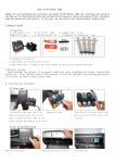
1
LE7
user manual for the LE7 product line (x2, x4, IR)
Image Engineering GmbH & Co. KG . Augustinusstraße 9d . 50226 Frechen . Germany
T +49 2234 995595 0 . F +49 2234 995595 10 . www.image-engineering.de
LE7
CONTENT
I REQUIREMENTS & INSTALLATION………………………………………………………………………...3
1.1 Hardware requirements
….……………………………………………………………………………….3
1.2 Installation……………………………….……………………………………………………………………3
II CONNECT THE HARDWARE………………………………………………………………………………..3
III USING YOUR LE7…………………………………………………………………………………………….4
IV LOW INTENSITY USE…………………………………………………………………………….…..……..4
V CALIBRATION / LED DEGRADATION………………………………………………………..……………4
5.1 iQ-LED spectral calibration…………………………………………………………………………………4
5.2 Spectrometer calibration…………………………………………………………………..………………..5
VI LE7 SPECTROMETER SETTINGS………………………………………………………………..……….5
VII SYSTEM TEMPERATURE, AMBIENT TEMPERATUTRE AND ENVIRONMENT CONDITIONS….5
VIII MINIMUM CAMERA DISTANCE AND POSITIONING…………………………………………….……6
IX USING DIFFERENT TEST CHARTS……………………………………………………………..………..6
X SAFETY INFORMATION…………………………………………………………………………………..…6
Image Engineering
2
LE7
I
REQUIREMENTS & INSTALLATION
1.1 Hardware requirements
System requirement is a PC with windows 7 (or higher) operating system and a free USB port.
1.2 Installation
Before conecting the hardware please install the iQ-LED control software. Follow the setup instruction
from you iQ-LED control software quick start guide or manual.
II
CONNECT THE HARDWARE
Connect the power cord to the power supply on the right side of your LE7. Connect the USB cable
from the LE7 to your PC and turn on the LE7, the power switch is placed beside the power supply. The
system will install the spectrometer and iQ-LED driver on your PC, this will take a few seconds. You
can check the installation in your hardware manager:
Hardware Manager: activ iQ–LED device and spectrometer
Image Engineering
3
LE7
III
USING YOUR LE7
After installation start the iQ-LED control software to use your LE7 with the transparency chart of your
choice. Before the first use it is recommended to calibrate your device, please follow the instruction in
your iQ-LED control software quick start guide or manual.
Also for usage of all Illumination funcionalityie please follow the quick start guide or manual of the iQLED control software.
IV
LOW INTENSITY USE
When using your system with very low intensity, the spectral measurement values will start to
fluctuate. The lower the intensity, the higher is the fluctuation. That does not mean that the generated
light is instable. The fluctuation of the values is caused by noise of the spectral measurement of the
internal spectrometer. The influence of the noise gets higher, the lower the light intensity is. When
using standard illuminants with intensity lower than 25lux it is not possible to get any approximately
correct value any more. If very low light intensities are required, please use a neutral density filter and
activate the neutral density correction in the iQ-LED control software. This way the light source will run
at higher intensity while having low intensity in the chart plane.
V
CALIBRATION / LED DEGRADATION
5.1 iQ-LED spectral calibration
The LEDs of the iQ-LED inside the LE7 are of many different types and wavelengths. Some LEDs will
change their intensity level and peak wavelength a bit in the first 500 working hours because of a burn
in effect. The LEDs also will degrade in intensity over their whole life time. To make sure that all
measurements, the auto generate and the standard illuminants are correct, you have to perform a
spectral calibration regulary. Also you have to consider the degradation of the LED when saving self
defined presets. If you save a preset with LED channels that uses its maximum intensity, it might be
that this intensity can not be reached after the burn in time or a long time degradation of the LED
anymore. In this case you will get a warning message from the iQ-LED control software.
While the first 500 working hours it is recommended to perform a spectral calibration every 50
operating hours. After the first 500 operating hours a calibration of every 150 working hours suffices.
Indications for a necessary spectral calibration is a not satisfying generate, aberration of the intensity
values or that the spectral curve of the predefined standard illuminants fit not to the corresponding
preset.Before performing a spectral calibration make sure:
•
•
•
•
•
•
the spectrometer works correct
the spectrometer settings are correct
all LED channels work correct
the dark measurement is correct
your measurement environment is correct
the ambient temperature is correct
How to perform the spectral calibeation is described in the iQ-LED control software manual.
Image Engineering
4
LE7
5.2 Spectrometer calibration
The internal spectrometer comes fully calibrated. It is recommended to recalibrate the spectrometer
once a year, regardless of the operating hours. Therefor a NIST traceable calibrated light source is
needed. If a spectrometer calibration is required please contact Image Engineering.
VI
LE7 SPECTROMETER SETTINGS
Please set the spectrometer settings in the iQ-LED control software to the following setting when using
your LE7 device:
LE7 x2
Integration time: 150ms
Binning / Boxcar width: 0
Scans to average: 1
LE7 x4
Integration time: 150ms
Binning / Boxcar width: 0
Scans to average: 1
LE7 IR
Integration time: 60ms
Binning / Boxcar width: 8
Scans to average: 2
VII
SYSTEM TEMPERATURE, AMBIENT TEMPERATUTRE AND
ENVIRONMENT CONDITIONS
Please place your system in a dry and constant tempered environment without any interfering light.
The optimal system temperature range, displayed in the measurement area, is between 32 and 38
degree Celsius.
The optimal ambient temperature range is 22 to 24 degree Celsius. The maximum ambient
temperature range is 19 to 29 degree Celsius. If the System temperature gets higher than 38 degree
Celsius please check your ambient temperature.
The system has an internal temperature management, if there is any error regarding the internal
temperature you will get a warning message and the system automatically turns off to avoid any
damage.
Image Engineering
5
LE7
VIII
MINIMUM CAMERA DISTANCE AND POSITIONING
Please note, that for charts with complete transparency parts a minimum distance between the
camera under test and the LE7 is required. For too short distances, the camera might capture parts of
the light source within the integrating sphere. This could cause irregular uniformity illumination in your
image. The minimum camera distance is depending on the viewing angle of the device under test.
So if the camera position is very close to the LE7 and you want to make sure that the distance and
position of your camera is correct, follow these steps:
1.
2.
3.
4.
The axis of vision of your camera has to be centered to the chart center point
Make sure that the camera is not contorted in reference to the chart plane
Remove the test chart and turn on a standard illuminant in low intensity (< 200lx)
Adapt the distance of the camera to the LE7 so that you will see the first row of both iQLED devices in the top and bottom borders of the image
5. From this position increase the distance of your camera to the LE7, so that both LED rows
will move out of the image, minimum increase of distance should be 45mm
6. Put in your test chart again and go on with your test
If you use a diffuse test chart like it is needed for shading or uniformity measurments you can put your
camera right in front of the diffusor chart.
IX
USING DIFFERENT TEST CHARTS
When using different test charts the measured values of your system could vary, depending on the
chart or filter. Also if you remove the chart the actual shown intensity will decrease. This does not
mean that your spectral arrangement or intensity of the LED devices has changed.
If you use testcharts that are significant different in transparency or inside refelction it is recommended
to recalibrate your LE7 together with the used chart. Please follow the software manual of the iQ-LED
control software.
X
SAFETY INFORMATION
•
Some LEDs are emitting invisible light in the IR and UV near area.
•
DO NOT look directly into the emitted light or look through the optical LED system.
•
DO NOT look directly in the open sphere or light source when using high intensities or
sequences with low response time.
•
DO NOT open the device without any instructions from the Image Engineering support and
when connected to the power supply.
Image Engineering
6