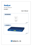
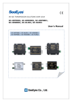
1
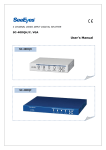
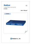
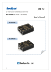
MULTIWAY MUX SC-04MC User's Manual SC-04MC 0 Precaution and Safety Guidelines Thank you for purchasing our product. Please read this manual carefully and fully understand the portions of the installation and operation instructions prior to installing and using the product. Should you have any part of them not understandable or if you have any problem during your installation or in using it, please contact us. Reproduction of this instruction or any part thereof without permission is strictly prohibited. You must read the precautions required for safe operation prior to using it and operate it correctly. Please understand that the contents of this operating instruction may differ slightly due to functional improvement of a product and based on the specification chosen by the user. You can use this product easier and more conveniently if you use the function of the product only after reading this operating instruction carefully. CAUTION RISK OF ELECTRIC SHOCK DO NOT OPEN CAUTION : TO REDUCE THE RISK OF ELECTRIC SHOCK, DO NOT REMOVE COVER. NO USER SERVICEABLE PARTS INSIDE. REFER SERVICING TO QUALIFIED SERVICE PERSONNEL. The lightning flash with arrowhead symbol within an equilateral triangle, is intended to alert the user to the presence of uninsulated “dangerous voltage” within the product’s enclosure that may be of sufficient magnitude to constitute a risk of electric shock to persons. The exclamation point within an equilateral triangle is intended to alert the user to the presence of important operating and maintenance (servicing) instructions in the literature accompanying the product. ※ 1 WARNING: To reduce the risk of fire or electric shock, do not expose this apparatus to rain or moisture. 1. Introduction 1.1 Overview SC-04MC receives the video signals taken by four (4) cameras and compares them with the previous screen, through which, if any camera detect the motion, this appropriate camera picture switches to full screen in case of only one picture in motion, 2 split screens in case of 2, and 4 split screens in case of 3 and more camera pictures in motion. By this, four (4) cameras can be connected with one (1) input of DVR, and it can save the input of DVR. 1.2 Major Functions and Features • Screen switching as per motion • One full camera screen, transmitting appropriate picture in motion, switches to split screen. When more than 2 cameras are connected and the motion is detected simultaneously and consecutively at 2 cameras, 2 divided screens are transmitted. When more than 3 cameras are connected and the motion is detected simultaneously and consecutively at more than 3 cameras, 4 divided screens are transmitted. Minimum recording field selection You can set the dwell time of the picture-transmitting camera when camera switching due to the motion. 10 steps of setup from 1 Field to 10 Field can be made available, which prevents the recording failure due to the poor perception of screen during playback if camera switching occurs frequently when storing at recording system like DVR. Easy setup Various setups can be made available by using the key of outside CASE. You can set the operation method as to not only the multi camera functions but also 4 divider (QUAD), 2 divider, and full screen multi camera as per user’s intention. The optimum performance can be obtained by the application of the devices suitable to the site condition through the sensitivity and speed adjustment of motion sensor. Loss warning indication at screen By indicating LOSS at screen if the loss occurs at camera input terminal, camera trouble can be identified. OSD (On Screen Display) Letter description for camera loss, camera title, and for presentlydisplaying channel can be shown at the screen on a real time. Compatible with NTSC and PAL This can be used even at all countries using different method because of its automatic perception system by NTSC/PAL. 2 Wide system application Through minimizing the product size by use of optimum circuit design and modern chip design and through adopting function design suitable to security product features, wide system application is possible. 1.3 Specification MODEL Input Output Input power Connection Input port Output Operation specification Temperature/ humidity Material / weight Dimension SC-04MC CVBS 1.0Vp-p 75 Ω term. CVBS 1.0Vp-p 75 Ω term. DC 5V 1A BNC-F 4 INPUT BNC-F 1 OUTPUT Refer to user manual -10℃ ~ +50℃ / 0 ~ 80% STEEL /550g 92 (W) x 94 (H) x 25.6 (D) mm 1.4 Display 1.4.1 Picture Screen According to the number of detected pictures in motion, picture that switches to either split screen or one full screen is displayed. 3 1.4.2 Camera Title OSD OSD of appropriate camera is demonstrated at above indicated position according to each screen. 1.4.3 LOSS OSD LOSS : 1 2 3 4 Appropriate camera number is indicated as OSD at upper right hand side if LOSS happens. 2. SC-04MC Installation 2.1 Picture Signal Connection SC-04MC can be used by connecting outside camera like watch-out camera to DVR or monitor as indicated below. 4 2.2 Cautions Make sure to turn off the power of equipment before installation Pay careful attention so as not to be hit by impact or vibration, which would be the cause of device breakdown. Avoid installing this device at the location where there is strong magnetism or radio wave, or where wireless device like radio or TV is used in the vicinity. Rated capacity of direct current device (adaptor) for power supply should be DC 5.0V/1A. This device should be installed in a cool place where direct sunlight does not shine and far from the place where people are coming and going, so that the device would not be damaged. If you keep using the device ignoring such condition as smoking or smelling, fire or electric shock might occur. In such cases you should turn off the power and ask A/S center of our company to get advice from our technical expert. You should always pay special attention to dangers possibly caused by wet floor, ungrounded power extension cable, worn-out power code, and lack of safety grounding, which might occur at working area. Check whether the power code is correctly connected when the power won’t be turned on. If screen is not lighted even though power is turned on, check whether input setting of camera from menu and connection between camera and input-output terminal are correctly made. Please check the connection status if recording does not work, and also check whether recording tape loaded into VCR is prohibited for recording. Please refer to user’s manual as to problems or questions besides above items. If you need any assistance from our technical expert, please ask to our A/S center for necessary advice. 3. SC-04MC System Setup 3.1 Button Function Guide Button Function Enter (setup) Used for entering the setup menu. Return the already-switched full-screen condition to the original state. Up /Down Used for shifting from the menu. Used for full-screen switching of each camera (UP: CAM1, DOWN: CAM3) in case of mode setup as QUAD. Left / Right Used for value changing from the menu. Used for full-screen switching of each camera (Left: CAM2, Right: CAM4) in case of mode setup as QUAD. Also used for screen rotating to left-right direction in case of mode setup as Panorama. 5 3.2 Menu Screen SETUP MENU SYSTEM / DISPLAY CAMERA SETUP DWELL TIME SET MOTION DETECT QUIT ►SETUP MENU (Initial screen) 1. ENTER key of the device will guide you to SETUP screen as above 2. ▲, ▼ button makes the menu to move, and by pressing ENTER key from the menu of your wish, pertinent menu of lower level is accessed. 3. There is the explanatory description at lower end of the screen as to the function of button. 4. Move to QUIT and press ENTER key in order to finish SETUP screen. 3.2.1 SYSTEM/DISPLAY SYSTEM/DISPLAY BORDER SET BORDER COLOR CAMERA TITLE LOSS CHECK MODE SELECT CAMERA 1 CAMERA 2 ON GRAY ON ON MULTI 1 2 ▲▼:MOVE ◄►:SELECT ENTER: EXIT If you press ENTER key after selecting SYSTEM/DISPLAY by use of the direction key of SETUP MENU, you can access to lower menu as above. Select the item by using ▲▼ button. Then, you can change the set value by using ◄► direction button. ►BORDER SET You can set contour whether it is necessary or not in order to facilitate separating the split picture clearly. ►BORDER COLOR This is the function for setting BORDER LINE color. 2 kinds of color, as either WHITE or GRAY can be set. ►CAMERA TITLE This is to set which number of camera picture (CAM1, CAM2, CAM3, CAM4) shall be displayed at screen. 6 ►LOSS CHECK This is to set whether to display or not after checking if there is anything wrong with the picture signal (LOSS indicating as 1234 at upper right side). ►MODE SELECT Select which function of multi-camera shall be used. PANOR: this is the operation mode that camera picture, rotating from screen center to left or right direction, is displayed at center of screen while showing 4 small screens at lower end of screen. MULTI: This mode is to show the picture as QUAD if there is no motion detected. But if there is any detected motion, the screen switches to FULL, DUAL, or QUAD state by this mode depending on the number of detectionperceived camera. QUAD: This is the mode that shows the picture as 4 split screens without screen switching. DUAL2: This is the mode for use as 2 split screens by screen switching function in case when only two cameras are connected. DUAL1: This is the mode for use as 2 split screens without screen switching in case when only two cameras are connected. SEQ: This is the mode that camera picture is displayed sequentially at regular time interval. FULL2: This is the mode that number 1 camera is shown at initial operation and if there is any detected motion, the screen switches to the detecting camera and keeps displaying as it is. FULL1: This is the mode that if any motion is observed while number 1 camera screen is displaying as base, the screen switches to appropriate detecting camera screen, and if the motion disappears, the screen returns to number 1 camera after certain time. ►CAMERA 1, CAMERA 2 If you select DUAL1, DUAL2 at MODE SELECT, the appropriate camera screen appears in sight. 2 picture channels which you wish to display are selected by this Mode Select. 7 3.2.2 CAMERA SETUP CAMERA CH-SELECT CAMERA SET SATURATION BRIGHTNESS CONTRAST HUE DEFAULT ▲▼:MOVE SETUP ◄►:SELECT 1 ON 32 32 32 32 OFF [CAM] ENTER: EXIT CH SELECT This mode is to select CHANNEL (CAMERA) of your wish. You can select CHANNEL (CAMERA) by using ◄► button. CAMERA SET This mode is to turn ON/OFF the camera picture input. If you set mode as OFF in case when camera is not connected to input terminal, appropriate channel will not be identified as LOSS. SATURATION, BRIGHTNESS, CONTRAST, HUE This is the function that sets color tones such as SATURATION, BRIGHTNESS, CONTRAST, HUE as to the camera of each channel. Range of change is 64 levels, which can be changed using ◄► direction button. DEFAULT If you choose set value of SATURATION, BRIGHTNESS, CONTRAST, HUE by pressing ◄► direction button, the setup, returning to OFF from ON state within 0.5 seconds, is changed to base value. 8 3.2.3 DWELL TIME SETUP DWELL TIME DWELL-F-F DWELL-F-D DWELL-F-Q DWELL-D-F DWELL-D-D DWELL-D-Q DWELL-Q-F DWELL-Q-D DWELL-N-Q SEQ-TIME DEFAULT ▲▼:MOVE ◄►:SELECT SET 15 /60 SEC 15 /60 SEC 15 /60 SEC 15 /60 SEC 15 /60 SEC 15 /60 SEC 15 /60 SEC 15 /60 SEC 120 /60 SEC 3 SEC OFF ENTER: EXIT This mode is to set the dwell time of present screen when any motion is detected. DWELL-X-X If motion is continuously observed during the preset time-span after initial detection by multi camera operation, screen switching is taking place. Switching time can be set for every switchover (time is 60=1sec). Abbreviation for F, D, Q means Full, Dual, Quad respectively. Example) DWELL-F-D : If two motions are detected at the time when motion detecting screen, being displayed as full screen, continues to be observed even after preset period of time, the setup switches to 2 split screen. SEQUENCE TIME The screen switching time can be set if Sequence Mode is selected at Mode Setting. DEFAULT If you press ◄► direction button, the setup, returning to OFF from ON state within 0.5 seconds, is changed to base value. 9 3.2.4 MOTION DETECT MOTION MASK MODE SELECT FIELD H. REGION SENSITIVITY LEVEL SENS SPATIAL SENS TEMPORAL SENS VELOCITY DEFAULT ▲▼:MOVE ◄►:SELECT DETECT 02 00 08 03 04 03 OFF ENTER: EXIT MASK MODE Motion detection can be set more sensitively depending on the comparative set value as to motion detecting perception. You can change the value by using ◄► direction button. - SELECTED FIELD: comparison method for motion detecting perception, 0~2(the bigger number means the more sensitive). - H (HORIZONTAL) REGION: this means the space of pixel value which is used for motion detection, assuming one screen is counted as 704x240(NTSC); 0~15 (the smaller number means the more sensitive) SENSITIVITY This is to set the sensitivity for motion detection. Depending on the set value, even small movement is detected as a motion. You can change the value by using ◄► direction button. The smaller number means the more sensitive. LEVEL SENS: sensitivity setting by the change of brightness. 0~15 SPATIAL SENS: This is the number of changed space to perceive the motion, assuming that the screen is divided into 196. 0~15 TEMPORAL SENS: sensitivity setting regarding temporary change. 0~15 VELOCITY Time to change the value that would compare with the present picture for the purpose of motion detecting perception can be set as 0~61. You can change the value by using ◄► direction button. DEFAULT Change the above set value as the base value. If you press ◄► direction button, the setup, returning to OFF from ON state within 0.5 seconds, is changed to the base value. 10 4. Warranty Certificate This product has passed thorough quality control and test, and if this gets broken during normal use, we provide 12 months warranty service. Model No. Serial No. Distributor Date you purchased Place you purchased Warranty Period Name Purchaser Address One (1) year from the date of purchase • Please • Please check this warranty indication first. contact your distributor after checking out any defect in the products. • The standard for repairing, replacement or reimbursement follows Customer. • Warranty content any defect under normal use within the warranty service period we give you free repair service according to the warranty certificate. • We charge you with the fee of parts and service despite of free warranty service period. Any breakage made without care such as: - Breakage or trouble made by natural disaster. - Breakage or trouble made by breaking the product guide or manual. - Breakage or trouble made by wrong power voltage or frequency. - When you want to reassemble for full system or replace parts within warranty service period. - When unauthorized person modified or made damage on the product trying to repair it. • Please note that we don’t support the breakage after warranty service period is expired. If the customer wants to get it repaired, we charge them with the fee. • The specification is subject to change without prior notice for quality improvement. SeeEyes Co.,Ltd 11 #502~506, Sunil Technopia, 440, Sangdaewon-Dong, Jungwon-Gu, Sungnam-Si, Gyeonggi-Do, Korea TEL : +82-(0)31-777-3508 FAX : +82-(0)31-777-3512 EMAIL : [email protected] http://www.sscctv.com/eng