1
HI-4416
System Readout
User Manual
ETS-Lindgren Inc. reserves the right to make changes to any product described
herein in order to improve function, design, or for any other reason. Nothing
contained herein shall constitute ETS-Lindgren Inc. assuming any liability
whatsoever arising out of the application or use of any product or circuit
described herein. ETS-Lindgren Inc. does not convey any license under its
patent rights or the rights of others.
© Copyright 1993–2013 by ETS-Lindgren Inc. All Rights Reserved. No part
of this document may be copied by any means without written permission
from ETS-Lindgren Inc.
Trademarks used in this document: The ETS-Lindgren logo is a trademark of
ETS-Lindgren Inc.
Revision Record | HI-4416, MANUAL | Part #H-600050, Rev. J
Revision
ii
Description
Date
Initial Release
July, 1993
A
Software Updates
March, 1995
B
Update
January, 1996
C
Changed Battery Charger
June, 1997
D
Added CE Label
June, 1997
E
Changed Charger Specs
August, 1999
F
Changed Area Code
February, 2000
G
Updated contact info. And added
charger manual as appendix.
February, 2006
www.ets-lindgren.com
Revision
Description
Date
H
Revised to current style standards
May, 2013
J
Updated part numbers in
Replacement and Optional Parts
September, 2013
www.ets-lindgren.com
iii
Table of Contents
Notes, Cautions, and Warnings .............................................. vii
General Safety Considerations .............................................. vii
1.0 Introduction .......................................................................... 9
Standard Configuration ............................................................................... 9
ETS-Lindgren Product Information Bulletin ............................................... 10
2.0 Maintenance ....................................................................... 11
Maintenance Recommendations ............................................................... 11
Replacement and Optional Parts .............................................................. 12
Upgrade Policies....................................................................................... 12
Service Procedures .................................................................................. 12
3.0 Specifications ..................................................................... 13
Electrical Specifications ............................................................................ 13
Physical Specifications ............................................................................. 13
Operational ............................................................................................... 13
4.0 Pre-Installation Tasks ........................................................ 15
Bench Test ............................................................................................... 15
Readout and Probe Bench Test ........................................................ 15
5.0 Operation ............................................................................ 17
Display...................................................................................................... 17
Keypad Operation ..................................................................................... 19
Battery Charging ....................................................................................... 23
Charging Procedure .......................................................................... 24
Battery Tips ...................................................................................... 24
Appendix A: Warranty ............................................................. 25
Appendix B: Communication Error Codes............................ 27
Appendix C: HI-4416 Operating Protocols ............................ 29
Communication Protocol ........................................................................... 29
Probe Data Format ................................................................................... 29
Valid Unit Types........................................................................................ 30
Appendix D: 491198-36 Battery Fast Charger ....................... 31
Safety Precautions.................................................................................... 31
iv
www.ets-lindgren.com
Introduction ............................................................................................... 31
Specifications ........................................................................................... 32
Maintenance ............................................................................................. 34
Fuse Replacement.................................................................................... 34
Operating Instructions ............................................................................... 35
Appendix E: EC Declaration of Conformity ........................... 37
www.ets-lindgren.com
v
This page intentionally left blank.
vi
www.ets-lindgren.com
Notes, Cautions, and Warnings
Note: Denotes helpful information intended to
provide tips for better use of the product.
Caution: Denotes a hazard. Failure to follow
instructions could result in minor personal injury
and/or property damage. Included text gives proper
procedures.
Warning: Denotes a hazard. Failure to follow
instructions could result in SEVERE personal injury
and/or property damage. Included text gives proper
procedures.
See the ETS-Lindgren Product Information Bulletin for safety,
regulatory, and other product marking information.
General Safety Considerations
Do not position the equipment so that it is difficult
to connect or disconnect cables into the back of the
unit.
See the ETS-Lindgren Product Information Bulletin for safety,
regulatory, and other product marking information.
www.ets-lindgren.com
vii
This page intentionally left blank.
viii
www.ets-lindgren.com
1.0 Introduction
The ETS-Lindgren HI-4000 Hazard Measurement System introduces
fiber optic technology for the acquisition of data from electric and magnetic fields.
The use of fiber optic cables for data transfer minimizes perturbation during field
measurements.
The heart of this system is the HI-4416 System Readout. This fiber optically
isolated remote readout/control can be paired with any one of the ETS-Lindgren
lines of electric and magnetic field probes to provide a wide range
(10 kHz to 40 GHz) of field measurements.
Standard features of the HI-4416 System Readout include data logging, a
recorder output, and a custom Liquid Crystal Display (LCD) with bar graph. The
data log feature captures up to 150 field readings for later review. The recorder
output provides a DC voltage proportional to the indicated field value. All
selection and control functions are input via the front panel keypad's membrane
switches; this keypad is configured in a matrix, allowing access to twelve
functions.
The HI-4416 uses an ASCII character string for communication with the probe in
both directions. See Appendix C: HI-4416 Operating Protocols for details of the
data format.
The HI-4416 System Readout may be used in conjunction with many
ETS-Lindgren probes. For a current list please contact ETS-Lindgren Customer
Service.
Standard Configuration
Rugged Aluminum Housing
Custom LCD Readout
Front Panel Keypad Matrix
Recorder Output (0 - 5 VDC)
Nickel-Cadmium (NiCd) Battery
Standard Quick Charger (115/230 Volt)
www.ets-lindgren.com
Introduction
9
ETS-Lindgren Product Information Bulletin
See the ETS-Lindgren Product Information Bulletin included with your shipment
for the following:
10
Warranty information
Safety, regulatory, and other product marking information
Steps to receive your shipment
Steps to return a component for service
ETS-Lindgren calibration service
ETS-Lindgren contact information
Introduction
www.ets-lindgren.com
2.0 Maintenance
Before performing any maintenance,
follow the safety information in the
ETS-Lindgren Product Information
Bulletin included with your shipment.
WARRANTY
Maintenance of the HI-4416 is limited to
external components such as cables or
connectors.
Warranty may be void if the housing is
opened.
If you have any questions concerning
maintenance, contact ETS-Lindgren
Customer Service.
Maintenance Recommendations
Maintenance of the HI-4416 System Readout is limited to external components
such as cables or connectors.
Any calibration or maintenance task that requires disassembly of the readout
must be performed at the factory. Contact ETS-Lindgren customer service before
opening the unit to avoid problems with your readout's warranty.
www.ets-lindgren.com
Maintenance
11
Replacement and Optional Parts
ETS-Lindgren may substitute a similar part or new part number with
the same functionality for another part/part number. Contact
ETS-Lindgren for questions about part numbers and ordering parts.
Following are the part numbers for ordering replacement or optional parts for the
HI-4416.
Part Description
Part Number
Battery Pack, 3.6 VDC,
Rechargeable
H-491038
Standard Fast Charger
(115/230 Volt)
H-491198-36
Cable, Fiber Optic, Glass, 2 meter
H-491106-02
Handle Assembly
H-491073
Carrying Case
H-491083
Upgrade Policies
Periodically, readouts are upgraded to enhance functionality. Contact
ETS-Lindgren Customer Service for the upgrade status of your system.
Service Procedures
For the steps to return a system or system component to ETS-Lindgren for
service, see the Product Information Bulletin included with your shipment.
12
Maintenance
www.ets-lindgren.com
3.0 Specifications
Electrical Specifications
Operating Temperature
+10º C to +40º C
(+50º F to +104º F)
Humidity
5% to 50% relative humidity,
non-condensing
Physical Specifications
Instrument Dimensions
(including connectors)
154 mm x 87 mm x 32 mm
(6.07 in. x 3.43 in. x 1.25 in.)
Weight
0.42 kg
(14.8 oz)
Operational
Battery
3.6 VDC, 1400 mA-h-NiCd
Battery Charger
115/230 VAC
approximately 1 hour
Battery Charger Jack
2.5 mm phone jack
Fiber Optic Connectors
Standard FSMA
Recorder Out Level
0 – 5 VDC, 1mA max (all ranges)
Recorder Out Jack
3.5 mm phone jack
Operating Life
(battery fully charged)
70 hours (idle)
80 hours (communicating)
Standard Fiber Optic Cable
200µm, graded index, multimode
www.ets-lindgren.com
Specifications
13
This page intentionally left blank.
14
Specifications
www.ets-lindgren.com
4.0 Pre-Installation Tasks
Before connecting any components, follow the
safety information in the ETS-Lindgren
Product Information Bulletin included with your
shipment.
Bench Test
Perform the following procedures to verify system operation.
READOUT AND PROBE BENCH TEST
1.
Remove the plastic caps from the readout's fiber optic connectors.
Remove the protective covers from the fiber optic cable assembly.
Save all protective caps and covers for future use.
2.
Visually inspect the tips of the fiber optic cables to make sure that they
are free of dirt and other contaminants. Connect the fiber optic cable to
the two connectors on the top of the readout; be sure to match the
cable connector colors to those on the readout connectors (yellow to
TRANSMIT; white to RECEIVE).
3.
Connect the other end of the fiber optic cable to the sensor connectors.
Be sure to match the cable connector colors to those on the sensor
connectors (white to XMIT; yellow to RCV).
4.
Set the ARM/OFF switch on the sensor to ARM.
www.ets-lindgren.com
Pre-Installation Tasks
15
5.
16
Press the ON/OFF keypad on the front panel of the HI-4416. All
segments of the LCD will activate for two seconds, then the version of
software installed in the HI-4416 will be displayed followed by the
current range of the probe connected to the readout. The HI-4416 will
then begin normal operation. Units of measure, current reading (if any),
bar graph, etc., will be displayed. If, after several seconds, the readout
indicates an error condition, see Appendix: B: Error Codes for
additional information.
Pre-Installation Tasks
www.ets-lindgren.com
5.0 Operation
Before connecting any components,
follow the safety information in the
ETS-Lindgren Product Information Bulletin
included with your shipment.
The HI-4416 does not shut down automatically. Be
sure to turn the instrument off when not in use.
Display
Connect a probe to the HI-4416. Make sure the switch on the probe is in the
“ARM” position and then turn the system readout on.
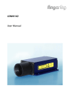
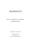
The HI-4416 uses a custom LCD to display the probe settings and field values
that are measured.
1. Under Range Indicator
7. Units of Measure Indicators
2. Bar Graph
8. Cursor Block
3. Over Range Indicator
9. Digital Display
4. Alarm Active Indicator
10. Axis Indicator
5. Maximum Reaidng Indicator
11. Battery Indicator
6. Power On Indicator
12. Autorange Indicator
www.ets-lindgren.com
Operation
17
Once the system readout is turned on, all segments of the LCD will activate for
two seconds, the version of software installed will appear, followed by the current
range of the probe connected to the readout. The HI-4416 then switches to
normal operation (measurement). The LCD readout displays the observed value
and the units of measure.
The bar graph along the top of the LCD window presents an analog
approximation of the measured field. Each bar graph segment represents five
percent of the full-scale reading in the current range. The bar graph is updated
7.6 times per second while the digital display is updated 1.9 times per second.
When the measured field strength is below 5% of full scale for the range in use,
the "Under Range" indicator at the left end of the bar graph appears and the
display will flash on and off. When possible, switch the range to permit a field
strength reading that does not trigger the "Under Range" indicator. If the field
strength exceeds full scale, the "Over Range" indicator at the right end of the bar
graph will appear and the characters “OL” will appear on the display. Select the
next appropriate range.
18
Operation
www.ets-lindgren.com
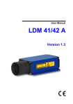
Keypad Operation
The operation of the HI-4416 System Readout is
controlled by membrane switches. To activate a
switch, press gently on the center of the pad with
your fingertip. Do not use hard or pointed objects.
On/Off—The On/Off keypad activates the readout.
At power-up, a self-test procedure is automatically performed. As part of this
procedure, all segments of the LCD will activate for two seconds, then the
version of software installed in the HI-4416 will appear, followed by the current
range of the probe connected to the readout. The System Readout then switches
to normal (measurement) operation. The HI-4416 does not require any warm-up
or settling time prior to use. Pressing On/Off again turns the readout off.
www.ets-lindgren.com
Operation
19
Mode Select—Selects one of the four modes of the keypad matrix.
For maximum operating flexibility, the HI-4416 utilizes a matrix for the upper
three keypads on the membrane switch panel. The function that each key
controls depends on the location of the cursor block (the dark rectangle located
at the bottom edge of the LCD). When the HI-4416 is turned on, the cursor
automatically positions itself above the left most of the four function columns on
the control panel. In this mode, the functions assigned to the three top keypads
are Range, Max and Zero
Pressing the Mode Select keypad moves the cursor block to the right, allowing
access to the three functions in that column. Each successive activation of the
pad moves the cursor another position to the right. From the fourth, or right most
position, the cursor returns to the first position. This configuration allows a total of
twelve different functions to be assigned to the upper three keypads.
Range— Displays the measurement range currently in use, changes the range.
When this keypad is momentarily pressed, the HI-4416 commands the probe to
transmit the range currently in use. The system displays this range for two
seconds before returning to the measurement mode. Pressing this keypad again
(while the current range is still being displayed) signals the probe to switch to the
next range; the readout displays the new range. Continuing in this manner will
step through all available ranges. When the highest range is reached, pressing
the keypad again returns you to the lowest (most sensitive) range.
The LCD presents the range in the form r X, where X is a number.
Since all probes do not contain the same number of ranges, the
maximum value of X depends upon which probe is connected to the
system readout. Consult the probe literature to determine the ranges
available for a particular probe.
Max—Displays the maximum reading.
During field measurements, the processor continually monitors and stores the
highest measured field value. To recall and display this value, press the Max key.
The maximum reading, denoted by the Max indicator near the right edge of the
LCD, appears on the display. This reading remains as long as the Max key is
pressed. When the Max key is released, the LCD retains the reading for
approximately two seconds, after which the Max memory location is cleared and
a new maximum reading is accumulated.
20
Operation
www.ets-lindgren.com
The maximum value is cleared when the HI-4416 is powered up, when the Max
key is released and when the unit of measure is changed. The Clear button does
not affect this reading.
If the maximum reading is over full scale for the range, 'OL' will appear
on the display along with the over range indicator.
Zero—Sends a zero command to the probe.
Selecting this command zeroes all ranges and axes. This mode establishes a
baseline for measurements by sampling all axes and ranges and subtracting
those values from each subsequent measurement.
Batt—Displays probe battery voltage and temperature. Refer to the manual for
your probe to determine if it is capable of communicating battery status.
Pressing this key with the probe connected and armed causes the LCD to display
a small battery symbol on the left side of the readout and the battery voltage of
the probe. After two seconds, the readout will also display probe temperature
in °F. After another two seconds, the readout returns to the measurement mode.
Compare the voltage reading you obtain with that stated in the probe manual.
When the probe's battery voltage decreases below a preset limit, the battery
symbol will blink; this indicates that the battery needs charging. If the battery
voltage is allowed to drop below that required for proper device operation, the
display will be blank.
This keypad can also be used to determine the battery status of the HI-4416.
When the battery symbol is flashing, toggle the probe's Arm/Off switch to Off, if
the symbol still blinks, then the battery in the system readout needs charging.
Units—Instructs the probe to change the units of measure, and displays the new
units.
Continue to press the Units keypad until the desired unit of measure appears on
the display. Just as for the Range command, the available units of measure
depend upon which probe is connected to the system readout; consult your
probe manual.
www.ets-lindgren.com
Operation
21
Clear Data—Clears all readings out of data log memory.
To perform this operation, press and hold the Clear Data keypad. The characters
"clr" will flash on the display for approximately two seconds. Continue pressing
the keypad until "000" appears on the display (these characters will not flash),
data log memory is now cleared. When you release the keypad, the system
readout returns to the measurement mode.
If this keypad is released while the "clr" characters are still flashing, data log
memory is unaffected. This helps prevent accidental erasing of data.
Log—Saves the current measurement in data log memory.
Pressing the Log keypad saves the reading in memory as this occurs, the
readout momentarily displays the three-digit identification number of the reading.
The data stored includes values, units of measure, over/under range indication
and active axes. Up to 150 measurements may be stored. When data log
memory is full, any additional log operations replace the value previously stored
in location 150 with the new value; all other memory locations remain
unchanged.
If this keypad is pressed for longer than two seconds, the just-logged data is
displayed
Prev—Accesses the last value stored in data log memory.
When the key is pressed the three-digit identification number of the stored value
is displayed for approximately one second then the stored value is displayed.
The readout continues to display this value as long as the Prev key remains
pressed. Approximately two seconds after releasing the key, the HI-4416 returns
to the measurement mode. Successive operations of the Prev key decrement the
displayed value toward the beginning of memory (value 001). If the key is
pressed while viewing value 001, the readout "wraps around" to the highest
stored identification number.
22
Operation
www.ets-lindgren.com
Next—Accesses the next value stored in data log memory.
The operation of this key is similar to that of the Prev key except that successive
operations of the Next key increment the displayed value toward the end of data
log memory. In addition, if the key is operated while viewing the highest stored
value, the readout "wraps around" to identification number 001.
If an under range value is logged and displayed, the measured value
along with the under range indicator arrow will appear. If an over
range value is logged and displayed, 'OL' and the over range indicator
arrow will appear.
X Axis—Commands the probe to enable/disable X axis measurements.
Y Axis—Commands the probe to enable/disable Y axis measurements.
Z Axos—Commands the probe to enable/disable Z axis measurements.
In some applications, it is advantageous to make field measurements
along only one or two axes. These three keypads allow you to enable
or disable each axis independently. The status of each axis is denoted
by the "XYZ" axis identifier characters in the lower left corner of the
LCD. If the axis identifier is visible, field measurement in that axis is
enabled; if not visible, the axis is disabled.
Battery Charging
The HI-4416 System Readout contains a rechargeable nickel-cadmium (NiCd)
battery. ETS-Lindgren, charges the internal NiCd battery of the HI-4416 at the
factory in order to test the HI-4416 System Readout prior to shipment. While
every effort is made to make sure that your readout arrives ready to use, we
cannot guarantee that this will be the case. Always check the condition of the
readout's battery prior to making any measurements.
A fully charged battery (nominal output voltage of 3.6 VDC) provides up to 80
hours of operation. When the batteries have discharged to 3.3 VDC, the readout
is still operational, but its battery needs charging. When the voltage drops below
3.18 VDC, the display will be blank.
www.ets-lindgren.com
Operation
23
CHARGING PROCEDURE
1.
Plug the charger into a suitable AC source.
2.
Make sure power to the readout is OFF. Insert the plug from the
charger cable into the readout's CHARGER jack.
3.
The battery pack is now charging. This may take approximately 1 hour,
depending on how deeply the batteries are discharged. When charging
is complete, the charger automatically goes into a trickle charge and
will continue to do so until the probe is disconnected.
BATTERY TIPS
NiCd batteries have several characteristics that can affect both their performance
and operating life. The following tips advise you how to take advantage of these
characteristics to get the most out of your readout’s battery.
24
Although NiCd batteries are rated for operation in temperatures from
-20 °C to 65 °C (-4 °F to 140 °F), using the System Readout in extreme
temperatures will reduce operating time significantly. The optimum
operating temperature range for these batteries is 20 °C to 30 °C
(68 °F to 86 °F).
The battery in the HI-4416 does not require periodic "deep discharges"
to reverse the capacity depleting "memory effect" caused by repeated
shallow discharges. However, undercharging can reduce battery
capacity.
If the battery in the HI-4416 appears unable to acquire or maintain an
appreciable charge, individual cells in the battery may be shorted or
damaged and the battery should be replaced. If, for any reason, your
battery needs replacement, contact ETS-Lindgren Customer Service
for assistance.
Operation
www.ets-lindgren.com
Appendix A: Warranty
See the Product Information Bulletin included with your shipment for
the complete ETS-Lindgren warranty for your HI-4416 System
Readout.
DURATION OF WARRANTIES FOR HI-4416 SYSTEM READOUT
All product warranties, except the warranty of title, and all remedies for warranty
failures are limited to one year.
Product Warranted
Duration of Warranty Period
HI-4416 System Readout
1 Year
www.ets-lindgren.com
Warranty
25
This page intentionally left blank.
26
Warranty
www.ets-lindgren.com
Appendix B: Communication Error Codes
When the HI-4416 detects an error condition during communication with a probe,
it will display an error message of the form EXX, where XX is a two-digit number.
The meaning of each error number is described below. Under certain
circumstances, it is possible for the user to correct the conditions causing errors
01 and 02: if not, or if the conditions that generate errors 03 - 12 develop and
persist, the probe must be repaired by ETS-Lindgren technicians.
Error
Cause
E01—No Response From Probe
Probe's ARM/OFF switch in OFF
position; faulty probe.
E02—Transmission Error (e.g., Parity)
The HI-4416 is ON, no fiber optic
cables are connected, and the
readout's connectors are aimed
toward a light source; faulty probe.
E03—Input Buffer Overflow
Too many characters contained
between the Start Character/Carriage
Return sequence.
E04—Invalid start character for probe
data
Start Character incorrect or not sent.
E05—Probe Data String Length Error
Data string does not conform to one
of the two correct string lengths.
E06—Invalid String for Reading Value
Data string does not conform to
correct format (four digits plus decimal
point).
E07—Invalid Range Value
Incorrect range character.
E08--Invalid Unit Value
Incorrect unit characters.
E09—Invalid Axis Enable Value
Value is other than "E" or "D".
E10—Invalid Battery Status Value
Value is other than "N", "D" or "F".
E11—Over Range Indicator
Value is other than "N" or "O".
E12—Invalid Recorder Out Value
Value is not in the range 0 – 255.
www.ets-lindgren.com
Communication Error Codes
27
This page intentionally left blank.
28
Communication Error Codes
www.ets-lindgren.com
Appendix C: HI-4416 Operating Protocols
Communication between the probe and the HI-4416 System Read Out is carried
out via an ASCII data string. The probe requires a dual fiber optic cable and only
responds when commanded. The HI-4416 continuously (at 7.6 Hz) sends the
probe a command for data and waits for a response. If a key that requires
information from the probe is pressed, the HI-4416 will send the appropriate
command to the probe and wait for a response.
COMMUNICATION PROTOCOL
Data Type:
RS-232 Serial
Data Mode:
Asynchronous
Word Length:
7 bits
Parity:
odd
Stop Bits:
1
Data Rate:
9600 baud
PROBE DATA FORMAT
The data sent to the HI-4416 is formatted as SDxx.xxuuugggobaaat:
S
Start Character (":")
D
Type Indicator ("D" = Controller, "#" = Listen Only)
xx.xx
Probe Reading (4 digits plus floating decimal)
uuu
Units of Measure (see next page for valid unit indicators)
ggg
Recorder Output/Bar Graph (0 - 255)
o
Over Range Indicator ("N" = Normal, "O" = Over Range)
b
Battery Status ("N" = Normal, "W" = Warning, "F" = Fail)
aaa
X-,Y-,Z-Axis (respectively) enable flag
("E" = Enabled, "D" = Disabled)
t
Terminating Character (Return)
www.ets-lindgren.com
HI-4416 Operating Protocols
29
VALID UNIT TYPES
The following table lists the unit codes that can be sent in the data string and the
unit indicator displayed on the HI-4416. If an invalid unit code is sent to the
HI-4416, no unit indicator is displayed and no error is generated.
An underscore indicates a space character, and is significant.
Unit Code From Probe
30
HI-4416 Unit Display
_V_
V/m
_V2
[V/m]²
KV_
k[V/m]
KV2
k[V/m]²
_A_
A/m
_A2
[A/m]²
MA_
mA/m
MA2
m[A/m]²
_W2
W/cm²
MW2
mW/cm²
UT_
μT
NT_
nT
_G_
G
MG_
mG
HI-4416 Operating Protocols
www.ets-lindgren.com
Appendix D: 491198-36 Battery Fast Charger
The HI-4416 System Readout contains a Nickel-Cadmium (NiCd)
battery and use the Series 4991198-36 Battery Fast Charger.
SAFETY PRECAUTIONS
Before operating the Series 491198-36 NiCd
Battery Fast Charger, see General Safety
Considerations in the ETS-Lindgren Product
Information Bulletin included with shipment.
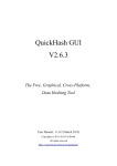
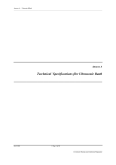
INTRODUCTION
The 491198-36 NiCd Battery Fast
Charger is a dual power source battery
charger. It charges 3.6 volt 1400 mAH
NiCd batteries and is powered by 120240 Vac line power or 12.5 Vdc. The
491198-36 uses a -(dV)/(dT) (negative
delta V) technique to determine when
the battery is fully charged, typically one
hour. With this technique, the charge
state of the battery has no effect other
than shortening the charge time.
Housed in a rugged enclosure, power enters the battery charger through a power
entry module, which contains the fuses, or an optional cigarette lighter plug
adapter. LEDs and the label on the front face of the unit provide operating
status. The battery charger connects to the device being charged through a
short cord terminated with a power jack.
An integrated circuit within the charger monitors the battery voltage and controls
the charging functions according to the charge state of the battery.
www.ets-lindgren.com
491198-36 Battery Fast Charger
31
SPECIFICATIONS
3.6 Volt 3 Cell NiCd Battery, 1400 mAH
(Rapid charge cells, 1.2 volts/cell)
NiCd Battery
ETS-Lindgren Part #H-491038
Power
Main—IEC filtered AC power input module
110 - 240 Vac, 500 mA MAX., 50 - 100 Hz
Power
Alternate—Automobile cigarette lighter to
2mm power plug adapter cord, 12.5 Vdc, 100
mA
Fuse
250 Volt, 1.0 Amp, Type T, 5 mm x 20 mm
Output
Open Circuit Voltage
15 Vdc
Fast Charge Pending
Current
60 mA
Fast Charge Current
1400 mA
Pulsed Trickle Charge
Current
50 mA
Output Voltage
(During Fast Charge)
3 - 6 Vdc
Environmental
10º to 40º C
Operating Temperature
50º to 104º F
Humidity
32
5% to 95% relative humidity, non-condensing
491198-36 Battery Fast Charger
www.ets-lindgren.com
POWER CABLE
This charger is shipped with a three-wire power cable. When this cable is
connected to an appropriate AC power source, it connects the chassis to earth
ground. The type of power cable shipped with each battery charger depends on
the country of destination.
ETS-Lindgren
Part Number
H-2217500
H-221100
H-222600
H-221600
H-221500
Power Cable Set Information
Volex #17500
Type SVT, Foil shielded, PVC Jacketed, 60°C
Molded PVC Grounding Plug NEMA 5-15P UC-004
Molded PVC Receptacle IEC320/C13 UC-005
18 Ga. 3 Cond. 10A-125V
Countries United States, Mexico, Canada
Kobiconn #173-7001
Type H05VV-F, PVC Jacketed, 70°C
Molded PVC Right-Angle Grounding Plug CEE 7/7 UC-814
Molded PVC Receptacle IEC320/C13 UC-051
1.0mm2 3 Cond. 10A-250V
Countries: Argentina, Austria, Brazil, Finland, France,
Germany, Israel, Italy, Holland, Korea, Netherlands, Norway,
Sweden, Turkey
QualTek #370001-E01
Type H05VV-F, PVC Jacketed, 70°C, Harmonized
Molded PVC Grounding Plug BS 1363, Fused UC-851
Molded PVC Receptacle IEC320/C13 UC-852
1.0mm2 3 Cond. 10A-250V
Countries: England, Ireland, Malaysia, Scotland, Singapore,
South Africa, Wales
Leeds Electronic Components #FFBS-1310
Type SAA, Ordinary Duty, PVC Jacketed, 75°C
Molded Grounding Plug AS3112 UC-822
Molded PVC Receptacle IEC320/C13 UC-051
1.0mm2 3 Cond. 10A-250V
Countries: Australia, China
Volex #2102H-C3-10
Type H05VV-F, PVC Jacketed, 70°C
Molded PVC Grounding Plug SEV 1011 UC-841
Molded PVC Receptacle IEC320/C13 UC-051
1.0mm2 3 Cond. 10A-250V
Country: Switzerland
www.ets-lindgren.com
491198-36 Battery Fast Charger
33
M AINTENANCE
User serviceable parts do not exist inside the
battery charger. Warranty may be void if the
battery charger housing is opened.
If the battery charger fails to operate, check for a blown fuse inside the power
entry module. If a fuse is blown it must be replaced with the same type and value
or an unsafe condition may result. If the battery charger still fails to operate, or if
you have any questions concerning charging your products, contact ETSLindgren Customer Service.
FUSE REPLACEMENT
NEVER attempt to change the fuse with the
battery charger plugged in.
The fuse is contained in the fuse drawer in the power input module. To access
the fuse, use a screwdriver to pry the drawer open and remove it from the
module. The drawer holds two fuses; the fuse towards the outside of the drawer
is a spare.
34
491198-36 Battery Fast Charger
www.ets-lindgren.com
If a fuse has blown, it must be replaced with the same type and value or an
unsafe condition may result.
After the fuse has been replaced, slide the fuse drawer back into the module.
Make sure that it snaps securely into its locked position.
OPERATING INSTRUCTIONS
Electronic instruments are delicate, operate the batter charger with
care.
The 491198-36 battery charger is intended to charge the 3.6 volt NiCd batteries,
either in the lab or in the field.
After connecting the battery charger to a proper power source, the battery
charger simply plugs into the charger jack on the HI-4416. The HI-4416 must be
turned off or the battery will not charge.
CHARGING INDICATORS
There are five LEDs located on the front of the charger that provide operating
information to the user.
The POWER ON LED (green) will remain illuminated as long as the
charger is plugged into the AC power source.
If the charger does not detect a battery, the NO BATTERY LED
(amber) light will illuminate.
When the charger does detect the unit’s battery, the PENDING LED
(amber) light illuminates while the charger qualifies the battery for fast
charge. If the voltage is below the safe fast charge level, the battery is
charged in the pulse trickle mode.
When the voltage is at a safe level the charger will switch to the fast
charge mode and the CHARGING LED (amber) light illuminates.
When charging is complete, the charger switches back to the pulse
trickle mode and the COMPLETE LED (green) light will illuminate. The
device can be left on the charger in this maintenance mode indefinitely.
www.ets-lindgren.com
491198-36 Battery Fast Charger
35
This page intentionally left blank.
36
491198-36 Battery Fast Charger
www.ets-lindgren.com
Appendix E: EC Declaration of Conformity
The EC Declaration of Conformity is the method by which ETS-Lindgren, Inc.
declares that the equipment listed on this document complies with the
EMC Directive and Low Voltage Directive.
Factory
Issued by
ETS-Lindgren, Inc.
ETS-Lindgren, Inc.
1301 Arrow Point Drive
Cedar Park, TX, USA 78613
1301 Arrow Point Drive
Cedar Park, TX, USA 78613
The products listed below are eligible to bear the CE mark:
– HI-4416 System Readout
– Series 491198-36 NiCd Battery Fast Charger
APPLICABLE REQUIREMENTS
Standard
Criteria
EN 50082-1
– Electromagnetic compatibility
– General immunity standard
– Part 1: Domestic commercial and light-industrial
environment
EN 55011
– CISPR 11 (1990) ed.2
– Threshold values and measuring methods for radio
interference by HF equipment for industrial scientific
and medical purposes
86/336/EEC
www.ets-lindgren.com
EC Declaration of Conformity
37
AUTHORIZED SIGNATORIES
The authorizing signatures on the EC Declaration of Conformity document
authorize ETS-Lindgren Inc. to affix the CE mark to the indicated product.
CE marks placed on these products will be distinct and visible. Other marks or
inscriptions liable to be confused with the CE mark will not be affixed to these
products. ETS-Lindgren Inc. has ensured that appropriate documentation shall
remain available on premises for inspection and validation purposes for a period
of no less than 10 years.
38
EC Declaration of Conformity
www.ets-lindgren.com