1
ECE Real-time System Laboratory
COEN421 Lab Manual
Revision No.: 1.3
Revision Date: 2014.12.18
Author: Dan Li, Iman Saboori, Samar Abdi
Department of Electrical and Computer Engineering
1515 St. Catherine West,
EV007.156
Montreal, Quebec, Canada
H3G 2W1 Tel: (514) 848-2424 x3148
Fax: (514) 848-2802
Web Site: www. ece.concordia.ca/~realtime
ECE Real-time System Laboratory
The Department of ECE
CONFIDENTIAL
This document and the information disclosed herein is
the confidential property of Concordia University.
Neither this document nor the information contained
herein shall be used, reproduced or disclosed to others
without the written authorization of Department of
Electrical and Computer Engineering.
Department of Electrical and Computer Engineering,
CONCORDIA UNIVERSITY.
All rights reserved.
All trademarks and trade names are the properties of their respective owners.
ECE-LAB-RT-02
2014.12.18
The Department of ECE
ECE Real-time System Laboratory
REVIEW
MANDATORY REVIEWERS
The final review of this document must be attended by the following people (or an
authorized delegate):
- Authors of this document
- A peer of the authors’
- Authors’ manager
- Relevant Professors and TAs
If these people are not present at the review meeting and are not represented by an
authorized delegate, it must be rescheduled.
INTERESTED REVIEWERS
The following people must be notified of the final review of this document but are not
required to attend the review:
- Technicians
- TAs
- Lab instructors
- The professors
Revision History
Date
Rev
Author
Reason for Change
2011.10.20
1.0
Dan, Li
Initial release of document.
2012.01.15
1.1
Iman Saboori
Add the experiments
2012.01.26
1.2
Dan Li
Revise the release.
2014.12.16
1.3
Dan Li
Change network settings, revise the
release.
2014.12.18
ECE-LAB-RT-02
ECE Real-time System Laboratory
The Department of ECE
ABSTRACT and Keywords
Abstract
This document contains the relevant persons, current lab infrastructure, equipments,
basic configurations, current support to the teaching and research, and account
information, experiments etc. This manual introduces the structure of real-time system
laboratory, consistence of each setup, user account information and experiments.
The manual provides a practical example in real-time programming and an overview of
the various experiments that are to be performed by students in the real-time lab.
This document is for the students and TAs:
• To setup the lab configuration in the real-time system lab;
• To Log in real-time network
• To manage workstation, target and plant(Qball);
Keywords
Real-time, Embedded system, Matlab/Simulink, QuaRC, QNX, RTOS
Reference
[1]
Matlab r2009 User Guide
[2]
Quanser Qball-x4 user manual
[3]
Advantech PCM-9375 User manual.
[4]
QNX 6.3.2 User guide.
[5]
The webpage of ECE Real-time lab: http://www.ece.concordia.ca/~realtime
ECE-LAB-RT-02
2014.12.18
The Department of ECE
ECE Real-time System Laboratory
GLOSSARY
This section defines all abbreviations and acronyms that appear in the document Any
words or actions which may not be readily understood are also included.
Term
Description
RTOS
A real-time operating system (RTOS) is an operating system (OS)
intended to serve real-time application requests. A key
characteristic of a RTOS is the level of its consistency concerning
the amount of time it takes to accept and complete an application's
task; the variability is jitter. A hard real-time operating system has
less jitter than a soft real-time operating system. The chief design
goal is not high throughput, but rather a guarantee of a soft or hard
performance category. A RTOS that can usually or generally meet a
deadline is a soft real-time OS, but if it can meet a deadline
deterministically it is a hard real-time OS. --wiki
SBC
A single-board computer (SBC) is a complete computer built on a
single circuit board, with microprocessor(s), memory, input/output
(I/O) and other features required of a functional computer. Unlike a
typical personal computer, an SBC may not include slots into which
accessory cards ("daughterboards") may be plugged. An SBC may
be based on almost any available microprocessor, and may be built
up from discrete logic or programmable logic. Simple designs, such
as built by computer hobbyists, often use static RAM and low-cost
eight or 16 bit processors.
QNX
QNX is a commercial Unix-like real-time operating system, aimed
primarily at the embedded systems market. The product was
originally developed by Canadian company, QNX Software Systems,
which was later acquired by Canadian BlackBerry-producer
Research In Motion.
2014.12.18
ECE-LAB-RT-02
Concordia University
ECE Real-time System Laboratory
Table Of Contents
1.
RULES ............................................................................................................................................. 1
Laboratory Rules ........................................................................................................................................ 1
Lab Safety Regulation ................................................................................................................................ 1
Task of Real Time Systems Laboratory ...................................................................................................... 1
Organization of Each Experiment .............................................................................................................. 2
Execution of the Experiments .................................................................................................................... 2
Lab Report.................................................................................................................................................. 2
Grading Scheme ......................................................................................................................................... 2
2.
INTRODUCTION .............................................................................................................................. 4
Overview .................................................................................................................................................... 4
Lab Structure and Seats ............................................................................... Error! Bookmark not defined.
Networks in the lab .................................................................................................................................... 5
Real-time Environment .............................................................................................................................. 6
GETTING STARTED ..................................................................................................................................... 8
HARDWARE COMPONENTS ..................................................................................................................... 10
SOFTWARE COMPONENTS....................................................................................................................... 18
3.
EXPERIMENTs ............................................................................................................................... 25
EXPERIMENT #1: Use Matlab/Simulink to Control Qball ......................................................................... 25
EXPERIMENT #2: develop socket programming class .............................................................................. 30
EXPERIMENT #3: Develop Communication Program with Target and Display Sensors ........................... 42
EXPERIMENT #4: Joystick Interface.......................................................................................................... 48
EXPERIMENT#5: Maneovue Qball by Joystick ......................................................................................... 58
4.
TEMPLATE FOR LAB REPORTS ....................................................................................................... 62
5.
FAQs ............................................................................................................................................. 64
List Of Figures
Figure 1: Lab Structure ........................................................................................................ 4
Figure 2: One Qball Set ....................................................................................................... 4
Figure 3: Changing password .............................................................................................. 9
Figure 4: Drives in Real-time Lab ....................................................................................... 9
Figure 5: SBC Board Diagram ............................................................................................ 11
Figure 6: Qball System ...................................................................................................... 13
2014.12.18
ECE-LAB-RT-02
i
ECE Real-time System Laboratory
The Department of ECE
Figure 7: Integrated Development Environment.............................................................. 20
Figure 8: Quarc Help ......................................................................................................... 24
Figure 9: The experiment #1 setup ................................................................................... 25
Figure 10: host_joystick Simulink model .......................................................................... 26
Figure 11: qball_motor_control Simulink model .............................................................. 27
Figure 12: IP address of workstation ................................................................................ 27
Figure 13: Change the host IP address ............................................................................. 28
Figure 14: Preferences menu ............................................................................................ 28
Figure 15: Enter Qball IP address ...................................................................................... 29
Figure 16: The experiment #2 setup ................................................................................. 30
Figure 17: The experiment #3 setup ................................................................................. 42
Figure 18: The experiment #4 setup ................................................................................. 48
Figure 19: The experiment #5 setup ................................................................................. 58
List Of Tables
Table 1: IP Tables ................................................................................................................ 5
Table 2: Qball IP tables ....................................................................................................... 5
Table 3: The qstream sensors data format ....................................................................... 42
Table 4: cqstreammsrv data format ................................................................................. 58
2
ECE-LAB-RT-02
2014.12.18
Concordia University
ECE Real-time System Laboratory
1. RULES
Laboratory Rules
Considering the large number of students attending the lab and in order for the lab to operate
properly, the students are asked to abide by the following rules:
• No eating or drinking is permitted in the laboratory.
• Overcoats and briefcases are not permitted in the laboratory.
• Students are supposed to sign in and sign out whenever they enter and leave the
laboratory.
• Students should bring their own laboratory manual. Any student who is more than 30
minutes late will not be permitted into the laboratory.
• The Qballs used in the experiments are very expensive and hence proper care must be
taken so that incidents like falling down the ground or bumping to the wall do not occur.
• Constant rebooting of the system should be avoided.
• Upon entering and leaving the safety cage, students should check whether the Qballs
are in proper stopping condition or not.
• Maximum care should be given to the Qballs, Joysticks and the SBCS.
• Students should immediately report to the demonstrator if any of these are damaged or
missing on their workbench. Failing to do so will result in students being charged for
damages or losses.
Lab Safety Regulation
The lab is a supervised lab. For the student’s safety and equipment security:
- The students should not play Qballs without TA’s supervision.
- Qball shall be put in cage when it is powered on, especially running a program on it.
- Wear a safety glass when you operate a Qball in close distance.
Task of Real Time Systems Laboratory
The main purposes of real time systems laboratory are as follows:
- To provide a practical experience working on a real-time platform.
- To work with Matlab/Simulink.
- To improve C++ and reusability skills.
- To improve programming syntax and algorithm checking.
- To learn QNX and the Integrated Development Environment (IDE).
- To provide experience in report writing.
2014.12.18
ECE-LAB-RT-02
1
Organization of Each Experiment
Each experiment is divided into the following sections:
- Objectives
- Diagram
- Lab description
- Class hierarchy diagram
- Design issues
- Hints and Sample code
- Check points
The first part gives the objectives of the experiment. The second part gives a rough idea about
the experiment in the form of a diagram.
Next comes the theoretical part of the experiment. The theory in this manual contains only a
brief experimental procedure and so students are asked to write their own descriptive
procedure in their lab reports.
The next section deals with the class hierarchy diagram. This is again a rough idea for students
to get a good understanding of the programming they are supposed to do. The class hierarchy
diagram provided in the manual is only a suggestion, and its up to the students to come up with
their own hierarchy diagram in their lab reports for each one of the experiments.
The last two sections provide a brief overview of the design issues, hints and sample code as
part of the different experiments.
Finally the experiment concludes with some questions as checkpoints
Execution of the Experiments
Each experiment must be studied in advance. Since the laboratory represents a significant
portion of the student’s practical training, it is imperative that the students perform all the
experiments. If a student has missed an experiment due to circumstances entirely beyond
his/her control, that student will have the opportunity to perform it at the end of the term. Any
student who misses more than one experiment will not be eligible for any form of passing
grade (“R” grade).
Lab Report
For each experiment a lab report must be written which can be regarded as a record of all
activities, observations and actual coding pertaining to that experiment. Lab report should be
well organized and well-presented and should contain as much information as possible.
Grading Scheme
The grading scheme is as follows:
2
ECE-LAB-RT-02
2014.12.18
The Department of ECE
ECE Real-time System Laboratory
Objectives, introduction
Results
Questions and discussion and conclusion
Preparation and participation*
10%
50%
20%
20%
* It is important that the student prepares for each experiment by reading the
instructions before the student goes to the laboratory. Therefore, both the preparation and the
participation will be evaluated during the laboratory.
2014.12.18
ECE-LAB-RT-02
3
2. INTRODUCTION
Lab Overview
This manual includes the general information of ECE Real-time System Laboratory (H-907). This
document is supposed to help you understand the real-time Lab about its present
configuration, usage and some issues.
The lab is made up of real-time develop workstation running Window 7 and some small board
computers (SBCs) as the targets running QNX and mounting various file systems from ECE realtime servers.
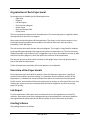
The bellowed diagram shows the structure of Real-time Lab.
Figure 1: Lab Structure
In the lab, there are four sets of Qball system.
Each set includes one Windows workstations, one
QNX SBC and a Qball-x4.
It can support four groups to use this lab at one
time. The maximum member in each group may
be three persons.
Figure 2: One Qball Set
4
ECE-LAB-RT-02
2014.12.18
The Department of ECE
ECE Real-time System Laboratory
Networks in the lab
ECE Real-time Network
One specified LAN is setup for real-time lab (192.168.141.0/24). It is used for running real-time
servers, user-management, system update on the equipment, etc. The following equipment
used for Embedded System lab are in this network:
- Two management servers: Tissot.realtime.private, Rolex.realtime.private
- Real-time Windows workstations with QNX package
- Real-time target machines (SBC) running on QNX
One gateway is setup to enable all real-time machines to access Internet. This network also
supports the labs of COEN320, ELEC481 and ELEC483.
Wireless Network
For wireless setup, one wireless router (G type) shall be used to setup a lab-area wireless
network, called GSAH, which is configured in access-point mode instead of Ad-hoc mode.
As factory default setup, Qball-X4 uses an ad-hoc peer-to-peer wireless TCP/IP connection for
communicating with the host computers. For real-time setup, the wireless more on Qball is
configured as access-point mode.
With a PCI wireless adapter the host computer (Development workstation) can have wireless
connection for working with the Qball-X4.
Here One G-type wireless router shall have four Ethernet ports as default. A SBC has two
Ethernet ports, one is connected ECE Real-time network, the other is connected this router to
enable it communicate with Qball also.
Table 1: IP Tables
Group#
1
2
3
4
Bly.encs
EBPC1
Pay.encs
EBPC2
Dry.encs
EBPC3
Sky.encs
EBPC4
Wired IP
192.168.141.186
192.168.141.50
192.168.141.192
192.168.141.52
192.168.141.189
192.168.141.54
192.168.141.190
192.168.141.56
Wireless IP
172.30.128.151
172.30.128.101
172.30.128.152
172.30.128.102
172.30.128.153
172.30.128.103
172.30.128.154
172.30.128.104
Table 2: Qball IP tables
Qball No Wireless IP
Wired IP
#224
172.30.128.224
172.16.0.224
#231
172.30.128.231
172.16.0.231
2014.12.18
ECE-LAB-RT-02
5
#232
172.30.128.232
172.16.0.232
#234
172.30.128.243
172.16.0.234
Real-time Servers
1. Real-time management server -Tissot.realtime.private (192.168.141.7)
Tissot provides service to real-time Windows workstations and acts as real-time domain
controller:
• Centralized users and groups management.
• Samba shared storage and Windows PDC.
• Network resource sharing- file server and web server.
2. QNX management Server - Rolex (192.168.141.8)
Rolex serves real-time QNX workstations, remote access QNX servers and QNX targets:
• QNX account management: support real-time project accounts,
• User remote access account.
• NFS for QNX machines: provide QNX /home for QNX workstations, servers and targets.
3. Remote QNX Access Servers
• Mackay.realtime.private – 192.168.141.3
• Cartier.realtime.private – 192.168.141.9
• Timex.realtime.private – 192.168.141.13
Real-time Environment
To write programs that run under the QNX Neutrino realtime operating system (RTOS), the first
thing you need is the QNX Software Development Platform (SDP). This includes the QNX
Momentics Tool Suite, which contains everything you need to develop programs that run on
Windows development host. The tool suite features an extensive Integrated Development
Environment (IDE).
The development host runs the QNX Momentics Tool Suite; the target system runs the QNX
Neutrino RTOS itself plus all the programs you're going to develop:
6
ECE-LAB-RT-02
2014.12.18
The Department of ECE
ECE Real-time System Laboratory
Real-time development Machine
In the lab real-time development host is Windows machine running Window 7 OS. The
following packages are installed to support real-time environment
• QNX Momentics 6.3.2
• Matlab 2009b
• QuaRC 2.1
• VMware (optional for QNX target)
Real-time Target machines
Real-time target machine is built on Advantech EBPC-3500 with PCM-9375 SBC. The SBC is
installed QNX 6.3.2 BSP.
A QNX target machine shall be ready so that the IDE on Windows development workstation can
interact with the QNX Neutrino on the target. The IDE supports host-target communications
using either an IP or a serial connection. Target systems need to run the target agent (qconn).
See Target agent in the IDE for more information.
Virtual Target
On each development workstation, QNX system can be running on local virtual machine,
(192.168.246.2). This virtual target can be used to debug your code without the support from
SBC.
To run Vmware, click the icon
, or from ‘start’ –‘ All programs’ –‘ Vmware server console’.
Shown in the following figure. To start QNX Virtual machine, click the green arrow or click the
command “Start this virtual machine’.
Note:
• The virtual machine may take serveral minutes to ‘boot up’.
• Its IP is ‘192.168.246.2’.
• No user login needed for debugging.
2014.12.18
ECE-LAB-RT-02
7
ACCOUNTS and DRIVES
Real-time Account
Once you have registered ECE real-time course COEN421, one specific real-time account shall
be created after new semester starts. Real-time account is separated with your ENCS user
account. Initially user real-time account is created based-on ENCS account and managed on ECE
real-time server ‘Tissot.realtime.private’. One user real-time userID is same as his/her ENCS
user ID but real-time password is created as same as the uer ID, e.g. if an user ID is named as
‘a_student’, then the pre-assigned password is ‘ student’.
Account of Real-time Domain
Press ‘Ctrl+lt+Del’, input your real-time ID and password, you can login any workstation in the
lab. When you first time login real-time domain, the workstation may take more time to create
your profile.
At the lab, you may choose any machine and use it interchangeably with the others. Your home
directory will be the same on every workstation.
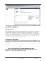
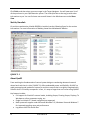
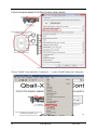
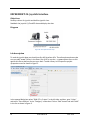
Once you log on real-time workstation with default password, you shall change it immediately.
Launch a web browser, and input the URL:
Error! Hyperlink reference not valid./tissot.realtime.private:8888/
Once the user enters his name and password, he can perform changes in his personal
configuration. The showed functionality is the following:
8
ECE-LAB-RT-02
2014.12.18
The Department of ECE
ECE Real-time System Laboratory
Figure 3: Changing password
Then you can change the current password in user’s corner.
QNX account
QNX account on real-time target (SBC) is only group type. A
group account can be used to upload your code to the
target. You can get a group account from your lab tutor.
In real-time lab, you can log in a real-time workstation, then
use SSH to connect its related target by a group account,
then you can upload your code.
Map ENCS Drives
Once you log on real-time workstation, the system shall run a script to map your ENCS network
drives G: and U: . The log-in pop-up window is shown as the followed:
The detailed information about these two network drives please refer to ENCS helpdesk
webpage. After network drives are mounted, system shows your drives, see the followed
screenshot.
Figure 4: Drives in Real-time Lab
2014.12.18
ECE-LAB-RT-02
9
Drives
• G: \ - ENCS personal Windows home
• U: \ - ENCS personal Unix home
• H:\ - ECE real-time home
When you first time log in, real-time system will create a working directory at “G:\realtime”,
which is the primary real-time workspace. You shall store your file and code under this
directory. The reason is G:\ drive is easy to access and more safe than H.
Remote Access
There are several remote QNX servers installed for real-time network.
• Mackay.realtime.private
• Cartier.realtime.private
As default, real-time user doesn’t have an account to access these servers. But you can use
them as a remote target when you run QNX Memotics on your PC.
If you need to access these servers directly, you can send a request. Once you have an account
on these servers, you can also remotely access the QNX system from outside Concordia by
using secure ssh. Here you may have to install a SSH client, such as Secure SSH client. Once you
have a SSH client, you can access the encs.login server: login.encs.concordia.ca by using ENCS
account, then you can use ‘ssh mackay.realtime.private’.
Once you remotely log in QNX, you can’t run an application with GUI.
HARDWARE COMPONENTS
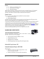
Real-time Windows Workstation
Real-time development workstation is built on Dell 390 PC, running
Windows 7 with some real-time packages.
•
Intel's Dual Core Processor (3.0GHz x 2 Cores)
•
CDRW/DVDRW Write DVD
•
500GB Hard Drive, 2GB DDR2
•
ATI X600 High Density Dual Output PCIe x16 Graphics Video
Embedded Target System –SBC
Embedded Industrial Chassis –EBPC-3500
Main Features:
• Built-in DC-to-DC power supply, accepts DC 12 V ~ 24 V
power input source, and ATX
• Accepts one PC/104 or PCI-104 or MIO card expansion
10
ECE-LAB-RT-02
2014.12.18
The Department of ECE
•
•
•
•
•
•
ECE Real-time System Laboratory
Supports one 2.5" HDD bay with anti-vibration design
Easy installation of HDD and DRAM
Built-in maximum I/O ports on the front, and optional video ports on the rear
Reserves I/O cutouts for easy I/O extension
Compact, robust construction
Simple and modularized service-friendly design.
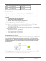
Single Board Computer
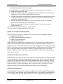
The PCM-9375 is a fanless, best-cost, performance 3.5" SBC (Single Board Computer) geared to
satisfy the needs for various industrial computing equipment. PCM-9375 is ideal for
communication, gaming and medical applications that require flat panel support using digital
displays with TTL or LVDS interfaces and two Ethernet ports.
For those who want superior performance for various low-power embedded applications, PCM9375 uses an AMD LX-800 processor clocked at 500 MHz, in conjunction with flexible DDR333
system memory through one SODIMM socket.
PCM-9375 offers convenient connector layout, easy assembly, multiple I/O, and includes two
10/100Mbps Ethernet, four USB (Universal Serial Bus) 2.0 and four serial ports for easy system
expansibility.
Figure 5: SBC Board Diagram
2014.12.18
ECE-LAB-RT-02
11
THE PLANT – QBALL
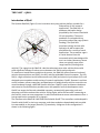
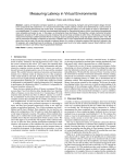
Introduction of Qball
The Quanser Qball-X4 (Figure 1) is an innovative rotary wing vehicle platform suitable for a
wide variety of UAV research
applications. The Qball-X4 is a
quadrotor helicopter design
propelled by four motors fitted with
10-inch propellers. The entire
quadrotor is enclosed within a
protective carbon fiber cage (Patent
Pending). The Qball-X4’s
proprietary design ensures safe
operation as well as opens the
possibilities for a variety of novel
applications. The protective cage is
a crucial feature since this
unmanned vehicle was designed for
use in an indoor laboratory, where
there are typically many closerange hazards (including other
vehicles). The cage gives the Qball-X4 a decisive advantage over other vehicles that would
suffer significant damage if contact occurs between the vehicle and an obstacle.
To measure on-board sensors and drive the motors, the Qball-X4 utilizes Quanser's onboard
avionics data acquisition card (DAQ), the HiQ, and the embedded Gumstix computer. The HiQ
DAQ is a high-resolution inertial measurement unit (IMU) and avionics input/output (I/O) card
designed to accommodate a wide variety of research applications. QuaRC, Quanser's real-time
control software, allows researchers and developers to rapidly develop and test controllers on
actual hardware through a MATLAB Simulink interface. QuaRC's open-architecture hardware
and extensive Simulink blockset provides users with powerful controls development tools.
QuaRC can target the Gumstix embedded computer, automatically generating code and
executing controllers on-board the vehicle. During flights, while the controller is executing on
the Gumstix, users can tune parameters in real-time and observe sensor measurements from a
host ground station computer (PC or laptop).
The interface to the Qball-X4 is MATLAB Simulink with QuaRC. The controllers are developed in
Simulink with QuaRC on the host computer, and these models are downloaded and compiled
into executables on the target (Gumstix [2]) seamlessly. A diagram of this configuration is
shown in the following figure.
12
ECE-LAB-RT-02
2014.12.18
The Department of ECE
ECE Real-time System Laboratory
Figure 6: Qball System
Setup Qball
•
•
•
Check that all motors are securely fastened to the vehicle frame.
Check that the propellers are firmly attached to the motors in the correct order:
clockwise propellers (viewed from the top) on the front and back motors, counterclockwise propellers on the left and right motors. Note that the back motor is indicated
by a bright colored marking on the Qball-X4 frame.
Check that the motors are firmly secured to the frame regularly (after every 2 hours of
flight). Over time, vibrations in the frame may loosen the motor mounts. If a motor or
mount feels loose, tighten it immediately.
This is a step by step guide to fly the Qball‐X4 unmanned aerial vehicle. It is highly
recommended to follow this guide particularly if this is the first time flying the Qball. There are
many referrals to the Qball user manual in this manuscript. So please keep it handy.
STEP 1: Except for connecting the batteries, the Qball should be shipped completely assembled
and it does not require any assembly. However, before flying the Qball each time please make
sure the motors are mounted firmly, the blades are not broken and securely fastened and all
the wires are connected. If anything is broken or loose you need o fasten, repair or change the
part before attempting to fly otherwise it will cause damage r harm to the equipment and/or
the operator.
STEP 2: Make sure y have a properly licensed QUARC, a running Matlab/Simulink, and all the
reacquired files.
2014.12.18
ECE-LAB-RT-02
13
STEP 3: Connect the two fully charged Li‐Po batteries to the Qball. Make sure they are
securely fastened using the provided straps. Also, make sure they are placed roughly under the
center of the frame. If not, this may cause imbalance and will affect the flight performance. For
the instructions on how to charge the batteries and their maintenance consult the Qball user
manual, Pages 10 and 17.
STEP 4: Make sure your wireless dongle (wireless card) is connected, installed and works
properly. Set the right IP address for the wireless connection and make sure it is connected o
the right network (GSAH). For detail instructions please refer to the Qball user manual, page 15.
STEP 5 (If you are using the OptiTrack positioning system): Before flying the Qball for the first
time you need to setup and calibrate the OptiTrack positioning system. Please refer to the
“Quanser OptiTrack Quick Start Guide” for more detail. Make sure that the OptiTrack
calibration square (for setting the ground plane) is oriented with the Z axis facing the operator
and X axis pointing to the left when setting the ground plane. This alignment is required for or
Qball autonomous flying using the provided models.
Remark: There are two main model files that will be used. One is the model file running on
the host ground station to get the joystick (and OptiTrack positioning) data and send the
information to the Qball. Second is the Qball control model running on the Qball which
gathers all the information and does the flight control. Note that there are safety features
in the Qball model that tries to land the Qball if the host model and Qball control model
communication stops for 1 second (see “Joystick from host\timeout safety” subsystem).
STEP 6: If this is the first time you are using the joystick you need to calibrate it in Windows.
Next, open the model file “HOST_joystick.mdl” (“HOST_joystick_optitrack.mdl” If you are using
the OptiTrack system). Build and run this model. Make sure the joystick channels are (in order):
Yaw, throttle, roll, pitch. Throttle should range between 0 and 1, and all other channels should
range from ‐1 to +1 with the positive value corresponding to positive rotation about the axes
according to the right‐hand rule (see Qball user manual or axes).
Remark 1: The joystick/OptiTrack model should always be started BEFORE starting the
Qball model. Failing to do so will cause a timeout in the Qball model and the Qball will not
e enabled. Even in closed‐loop (sonar/OptiTrack) control modes the joystick throttle is till
used to enable the Qball (throttle >= 10% motors enabled, < 10% motors disabled).
Remark 2: The left stick controls the throttle and yaw (down‐>up is 0‐>100% throttle,
left‐>right is rotate counter‐clockwise ‐> clockwise about vertical axis) and the right
stick controls pitch and roll (down‐>up is pitch backwards ‐> forwards, left‐> right is
roll left‐>right). The standard point‐of‐view is always with the Qball facing away from
the operator, so he/she is viewing the Qball tail.
STEP 7: The Qball control model should be configured to target the gumstix on the Qball of the
Qball user manual.
14
ECE-LAB-RT-02
2014.12.18
The Department of ECE
ECE Real-time System Laboratory
STEP 8: In the Qball control model under the “joystick from host” subsystem you will see a
“Stream Client” block. Change the URI to match the IP of the host ground station PC. This block
receives the packets from the host joystick/OptiTrack model and passes the joystick commands
(and OptiTrack data) to the various Qball control subsystems.
STEP 9: Familiarize yourself with the Qball model. The main subsystems from the top level re
broken down into the following:
“Calculate Roll Pitch Heading Height”: This subsystem computes the Qball pose or states by
using the information provided by the HiQ sensors.
“Control signal mixing”: Combines the throttle, roll, pitch and yaw control signals to calculate
the output for each of the 4 motors. This subsystem also contains some safety for enabling the
motors.
“HiQ”: This is where you will find the HiQ DAQ blocks. Motor values (4 PWM output channels)
are output and various sensor values are read in. There is a large gain block just before the “HIL
Read Write” block that is primarily used to disable the motor outputs for testing. Change this
gain to [1 1 1 1]*0 to disable the motors or [1 1 1 1]*1 to enable the motor outputs.
“Joystick from host”: As mentioned before this subsystem receives packets from the host model
containing joystick (and optitrack) information. It also includes timeout safety and will land the
Qball if a timeout is detected.
“Mode control”: This subsystem controls the operating mode of the Qball, which can be either
joystick control or OptiTrack (or sonar depending on the selected source of height) control.
“Pitch controller”: This subsystem includes the controller for stabilizing the pitch of the vehicle
and to make it follow the commanded pitch. Pitch reference commands are either coming from
the joystick or from a position controller.
“Yaw controller”: This subsystem generates a yaw control signal from either the joystick or
measured heading depending on the mode setting.
STEP 10: It is important to know that the Qball control model has two operating modes for the
height, position, and heading control. In the “Mode control” subsystem, make sure all of the
switches are set to JOYSTICK ON if you want to use the joystick to control the flight. You can
then switch the mode to use autonomous control for height, position, and heading of the Qball.
(Joystick mode is always recommended if this is the first time flying the Qball)
STEP 11: Disable the Qball motors by setting the gain to [1 1 1 1]*0 in the “HiQ” subsystem.
STEP 12: Compile and run the Qball control model. Make sure that the joystick packets arriving
at the Qball are correct when you move the joystick. Check the sensor outputs and pose
measurements (roll, pitch, and heading). Note that the heading offset may need to be adjusted
2014.12.18
ECE-LAB-RT-02
15
(you can find this setting in “Calculate Roll Pitch Heading Height \ Calculate heading”
subsystem).
STEP 13: Make sure the Qball model is stopped. Enable the motors through the gain block to [1
1 1 1]*1 in the “HiQ” subsystem.
STEP 14: Make sure the host joystick (OptiTrack) model is already running and the throttle is at
zero when starting the Qball control model.
STEP 15: When you are comfortable with the controls and are ready to try flying start the Qball
control model. Keep the throttle at zero for 3 seconds (the motors are always disabled for the
first 3 seconds to ensure the communication to the host model is working). Slowly increase the
throttle to get the motors to start spinning. If you wish, you can double‐check the motor
rotations are correct (see the Qball user manual, Page 10). Slowly increase e throttle until the
Qball begins to take off. Try hovering at a height of 10‐30 cm to become comfortable with the
system.
Remark 1: In the event you want to stop the system you can always bring the throttle to
Zero to stop the motors or you can stop the model.
Remark 2: It is always recommended to have a second operator to monitor the models
while you are flying. Here are some important points you need to pay attention to: Some
safety is built into the Qball model and in the event of a timeout you will get a message
popup on the screen. In case you are using the OptiTrack positioning system you will also
get an OptiTrack timeout message if the system cannot track the marker anymore.
***ALWAYS FULLY STOP THE MODEL AND PUT THE JOYSTICK THROTTLE TO ZERO BEFORE A
PPROACHING THE QBALL***
Recharge Batteries
Qball is using two 2500mAH 11.1v 3S1P Li-Polymer Battery packs. There is a low battery
warning message that comes up when the batteries reach 10.6V or less. Change the batteries
before they get very low or it may damage the batteries such that they can no longer be
recharged.
16
ECE-LAB-RT-02
2014.12.18
The Department of ECE
ECE Real-time System Laboratory
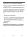
Charge the battery
The following steps show how to recharge the battery set:
•
Connect the batter to A6 charger.
•
Power the charge.
•
Select the battery type ‘LiPo 11.1v 3S’ , press the
Start/Enter key to make a blink, then change the
value with INC or DEC key.
•
Set the charge current to 2.0A.
•
Start the charging process. Press Start key for more
than 3 seconds to start the process.
•
Confirm the settings. R: shows the number of cells found by the charger, and S: is your
setting. If both numbers are identical, you can start the process.
•
Monitor the situation during charge process.
2014.12.18
ECE-LAB-RT-02
17
•
To stop charging press Stop once.
Install the batteries.
Placing the Qball-X4 upside down so that it rests on the top of the cage. Align the two Qball-X4
batteries with the plate located on the bottom of the frame and secure the batteries tightly
using the two velcro straps as shown in bellowing Figure. Connect the batteries to the battery
connectors and place the Qball-X4 upright again so it rests on the bottom of the cage.
SOFTWARE COMPONENTS
Following are the main header files containing different class interfaces, which could be used in
coding for the various lab experiments. These interfaces, in fact, provide a clear design strategy
for the various tasks to be accomplished in each of the experiments.
QNX & Momentics IDE
Introduction
The QNX Momentics development suite 6.3.1 includes the following parts:
18
•
QNX Neutrino RTOS - The whole point of it all. If Neutrino is the "engine" that will
empower the embedded system you're developing, then QNX Momentics is the
"factory" where you modify your engine as well as build, test, and finish your vehicles.
•
Integrated Development Environment - This is your toolbox. The IDE's task-oriented
interface helps you quickly set up your project, choose your programming language,
choose a target processor, compile your code, connect to your target, transfer your
application to your target, run it, debug it, profile it, and fine-tune it.
ECE-LAB-RT-02
2014.12.18
The Department of ECE
ECE Real-time System Laboratory
•
Command-line tools - If you aren't using the IDE, you can use command-line tools to
develop applications. For example, you can use qcc to compile and link, and mkifs to
create an OS image.
•
Libraries - ANSI C, POSIX, Dinkum C++ (full and embedded), GNU C++ (x86 only),
graphics, widgets, compression, etc.
•
Documentation - How-to guides, references, context-sensitive help, and technotes.
For more information, please visit www.qnx.com.
Get help
Within the IDE, Click Help-->Help Contents. There you'll find several booksets listed, including A
Roadmap to the QNX Momentics Development Suite. The other documents listed, such as the
Workbench User Guide and JDT Plug-in Developer Guide, pertain to the Eclipse platform and its
various plugins.
Overview of the documentation
For the latest documentation, In QNX Momentics, the online documents are in HTML, which
you can access in the IDE's help system. On self-hosted QNX Neutrino systems, you can also
look at the documentation in the Photon helpviewer.
or to download PDF versions, visit QNX website, http://www.qnx.com. Printed books are also
available.
To help you find your way around the QNX Momentics documentation set, QNX has provided a
documentation roadmap.
QNX Momentics Development Suite
2014.12.18
ECE-LAB-RT-02
19
Quickstart Guide: 10 Steps to Your First QNX Program, a tutorial that helps you install QNX
Momentics on a host machine, install the QNX Neutrino RTOS on a target machine, set up
communications between the two systems, and then use the IDE to develop a program on the
host machine and run it on the target.
Integrated Development Environment
IDE User's Guide, Describes the QNX Momentics Integrated Development Environment, how to
set up and start using the tools to build Neutrino-based target systems, etc..
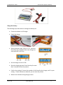
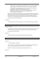
Start Momentics
Start the QNX Momentics IDE on your development host. The first time you start the IDE, it asks
you to choose a workspace, a folder where it can store your projects and other files. The IDE
then displays its Welcome page. When you're ready to start, click the Momentics icon
Figure 7: Integrated Development Environment
:
It is a quick start to QNX Momentics 6.3.2 Integrated Development Environment (IDE). The
purpose is to introduce you to the QNX software environment of the real time system
laboratory, and to help you start writing your first program for QNX real-time system in a short
time.
20
ECE-LAB-RT-02
2014.12.18
The Department of ECE
ECE Real-time System Laboratory
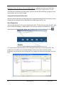
Add a Target
A target system may be a SBC, a remote QNX server or a local virtual QNX machine. It must be
able to respond to requests from the development environment. Before adding a target, you
shall confirm a target available by the command ‘ping’.
To access your target system from the IDE, you have to create a target project. Open the
System Information perspective: in the Window menu, select Open Perspective-->QNX
System Information. In the empty Target Navigator view, press the right mouse button and
select New QNX Target... from the context menu:
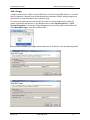
Now provide a name for your target system and enter its IP address in the corresponding field:
or
2014.12.18
ECE-LAB-RT-02
21
Click Finish, and then select your new target in the Target Navigator. You will now see a list of
all the processes in your QNX Neutrino system. The views (the tabs at the top) provide other
information to you. You can find even more useful views in the Window menu under Show
View.
Matlab/Simulink
On real-time workstation, Matlab R2009b is installed; see the following figure for the version
information. For more information of Matlab, please check Mathworks website.
QUARC 2.1
About QuaRC
From teaching the fundamentals of control system design to conducting advanced research
where hard-real time is critical, QUARC 2.1 offers unbeatable power and flexibility. QUARC is a
rapid-prototyping and production system for real-time control that is so tightly integrated with
Simulink that it is virtually transparent. In fact, it is easy to forget that one is even using QUARC!
Key features include:
• Full support for Simulink® external mode, including Scopes, Floating Scopes, Displays, To
Workspace, online parameter tuning, etc.
• Single or multiple PC / board configurations supported
• Multi-processor support under Microsoft Windows® XP, Windows Vista and Windows 7
for improved sampling rates and performance
• Log data to MAT-file and M-files
22
ECE-LAB-RT-02
2014.12.18
The Department of ECE
ECE Real-time System Laboratory
•
•
•
•
Run Multithreaded and Multirate models
Run more than one model on a single target or multiple targets at the same time
Standalone controller execution
Support for multiple targets (OS’s and chipsets), such as Windows® XP, Windows Vista
and Windows 7 (soft real-time) and QNX (hard real-time)
• Flexible and extensible communications framework enabling distributed control, device
interfacing, teleoperation and general interprocess communication between models
and local or remote applications
• Unified, expandable data acquisition architecture supporting cards from Quanser,
National Instruments and other manufacturers
• Support for asynchronous threads in Simulink® models - ideal for asynchronous
communications, etc.
More detailed information, please check QuaRC website:
http://www.quanser.com/english/html/quarc/fs_overview.htm
QuaRC on Development Workstation
QUARC consists of a number of components that make this seamless integration possible:
• QUARC Code Generation
• QUARC External Mode Communications
• QUARC Target Management
• QUARC Code Generation
QUARC extends the code generation capabilities of Real-Time Workshop by adding a new set of
targets, such as a Windows target and QNX x86 target. These targets appear in the system
target file browser of Real-Time Workshop. These targets change the source code generated by
Real-Time Workshop to suit the particular target platform. QUARC automatically compiles the C
source code generated from the model, links with the appropriate libraries for the target
platform and downloads the code to the target. All of these operations are performed with a
single click of a button!
QUARC External Mode Communications
QUARC provides an "external mode" communications module that allows the Simulink diagram
to communicate with real-time code generated from the model. Click Connect on the Simulink
diagram and the generated code is automatically loaded on the target, if necessary. Start the
model by simply clicking the Start button. Tune parameters of the running model by changing
block parameters in the Simulink diagram. Open a Simulink Scope or any other sink in the
diagram and view the status of that signal in the model as it runs on the target!
QUARC Target Management
Generated code is managed on the target by an application called the QUARC Target Manager.
It is the QUARC Target Manager that allows generated code to be seamlessly downloaded and
run on the target from Simulink. Additional components of the QUARC Target Management
2014.12.18
ECE-LAB-RT-02
23
System provide access to data acquisition hardware, communications protocols, etc. The
management system also supplies the ability to dynamically reconfigure the models running on
the target; a model may be replaced with another model while it is running with no
interruptions! Learn more about the dynamic reconfiguration capabilities of QUARC in the
Dynamic Reconfiguration section of this documentation
For detailed information, please check QuaRC Help on real-time Windows workstation. Click
start – All Program – Quanser – QuaRC – QuaRC Help.
Figure 8: Quarc Help
QuaRC on SBC QNX
QUARC v2.1 is installed on real-time target machine (SBC) which is running QNX Neutrino
v6.3.2. A "target" is a combination of operating system and processor for which QUARC can
generate code from a Simulink diagram. This can be done on Real-time Windows workstation.
The SBC target is where the QUARC-generated code runs.
The best deterministic hard-real-time performance with QUARC is currently achieved when
running the model on a QNX Neutrino target, taking advantage of the QNX Real-Time Operating
System (RTOS) industry-proven technology.
The corresponding QUARC controller robustly runs in hard-real-time under QNX at up to 1-kHz
sample rate (i.e., 1-ms sampling interval) by using the Quanser Stream API (to get the updated
sensor data in realtime). In addition, the Quanser Target API is also used to start/stop the
QUARC control model from the QNX custom application.
24
ECE-LAB-RT-02
2014.12.18
The Department of ECE
ECE Real-time System Laboratory
3. EXPERIMENTs
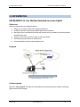
EXPERIMENT #1: Use Matlab/Simulink to Control Qball
Objectives
After this experiment you should be able to:
• Safely turn on/off the qball and change the batteries,
• Establish a wireless connection between qball and workstation
• Work with Quarc and Matlab Simulink and compile and run models on both workstation
and qball sides and:
• Receive and monitor the sensor data on the workstation,
• Read back the joystick data on workstation
• Send command to control rotors speed on the
Diagram
Figure 9: The experiment #1 setup
Lab description
Open the “host_joystick” Simulink file in matlab and connect the blocks as show in following
figure and save the changes.
2014.12.18
ECE-LAB-RT-02
25
Figure 10: host_joystick Simulink model
Compile your model by clicking on the “Incremental built” button in toolbar as it shown in
following figure.
After that you compiled the model, connect the joystick to workstation and click on the
“connect to target” button in toolbar.
Now you can run the model by clicking on “start real-time code” button as shown in following
figure.
Start real-time code button in Simulink toolbar
Open the “qball_motor_controll” Simulink file in matlab and connect the blocks as shown in the
following figure .
26
ECE-LAB-RT-02
2014.12.18
The Department of ECE
ECE Real-time System Laboratory
Figure 11: qball_motor_control Simulink model
Now, run “cmd.exe” to open command terminal. Use “ipconfig” command to find the IP
address of the workstation.
Figure 12: IP address of workstation
Change the host IP address in the “qball_model_control” to the workstation IP address.
2014.12.18
ECE-LAB-RT-02
27
Figure 13: Change the host IP address
Click on “QUARC” menu and select “Preferences …” to open “QUARC Preferences” dialog box.
Figure 14: Preferences menu
28
ECE-LAB-RT-02
2014.12.18
The Department of ECE
ECE Real-time System Laboratory
Enter the IP address of Qball as the target address.
Figure 15: Enter Qball IP address
Turn on the qball as it is described before, and make sure you can connect to it via wireless
network using the ping command in cmd shell. Now compile the model by clicking on the
“Incremental built” button in toolbar and click on the “connect to target” and run the model.
You should be able to change the speed of qball propellers by the joystick handles. To stop
running the model you should click on “stop real-time code” button in toolbar as depicted in
below figure.
Stop real-time code button in Simulink toolbar
Check points
Your performance in this lab will be evaluated based on the following operations properly being
implemented.
• Be able to turn on/off the qball safely.
• Complete, compile and run host_joystick model in Simulink.
• Complete, compile and run qball_motor_control model in Simulink.
• Change the speed of qball propellers using the joystick
2014.12.18
ECE-LAB-RT-02
29
EXPERIMENT #2: develop socket programming class
Objectives
You should develop a csocket class to do the followings:
• Establish a TCP/IP connection
• Bind to a TCP port
• Listen to connection requests
• Accept connection requests
• Receive data
• Send data
Diagram
Figure 16: The experiment #2 setup
Lab description
Before you start your work please make sure you add “socket” library in the library list of IDE
or use the -l socket option to qcc to link against this library. To add a library in IDE, open the
project->properties menu as shown in figure 2.
In the opened dialog box select “QNX C/C++ Project” in the left side, and then, goto “Linker”
and select “Extra libraries” in the “Category” combo box. Click on “Add” button and add
“socket” in the list as shown in following figure.
30
ECE-LAB-RT-02
2014.12.18
The Department of ECE
ECE Real-time System Laboratory
After developing the csocket class, you should create two threads as sender and receiver and
send a test message from the sender thread to the receiver thread and display it. You can use
following sample codes to implement csocket class and test its functionality.
List 1: csoket.h
//=========================================================================
#ifndef _CSOCKET
#define _CSOCKET
// header files needed for socket and TCP programming
#include <sys/types.h>
#include <sys/socket.h>
#include <netinet/in.h>
#include <arpa/inet.h>
//=============================================================================
class csocket{
private:
public:
2014.12.18
int sockfd; // socket descriptor
int send_recv_sockfd; // socket descriptor of accepted connection
struct sockaddr_in addr;
struct sockaddr_in client_addr;
unsigned short int port;
int
backlog; /* how many pending connections queue will hold */
ECE-LAB-RT-02
31
csocket();
~csocket();
};
int connect(unsigned short int HostPort, char * HostIP);
int bind(unsigned short int port);
int listen();
int accept();
int send(char * buff, int len);
int receive(char * buff, int len);
int close();
#endif
List 2: csocket.cpp
// standard needed header files.
#include <unistd.h>
#include <iostream.h>
#include <errno.h>
#include <sys/types.h>
#include <unistd.h>
#include <fcntl.h>
#include "csocket.h"
using namespace std;
csocket::csocket(){
backlog=10;/* set the default number of pending connections queue to 10 */
send_recv_sockfd=-1; // mark the send_recv_sockfd as invalid
open();
}
csocket::~csocket(){
close_session();
close();
}
int csocket::open(){
// open a TCP socket and save the handler in sockfd
return 0;
}
int csocket::close_session(){
// check that is session socket created or not
// close the session socket if the socket descriptor is valid
send_recv_sockfd=-1;
return 0;
}
int csocket::close(){ // close the accepted connections
// chech that is socket created or not
32
ECE-LAB-RT-02
2014.12.18
The Department of ECE
}
ECE Real-time System Laboratory
// close the socket if the socket descriptor is valid
sockfd=-1;
return 0;
int csocket::bind(unsigned short int port){
// the return value of function
int returnval;
// set the port number
this->port=port;
/* host byte order */
addr.sin_family = AF_INET;
/* short, network byte order */
addr.sin_port = htons(port);
addr.sin_addr.s_addr = INADDR_ANY; // local host
/* zero the rest of the struct */
memset(&(addr.sin_zero), 0, 8);
// to make sure it does not block when socket related functions are called
int flags;
flags=fcntl(sockfd,F_GETFL,0);
if(flags==-1){
cout<<"Error in fcntl() call."<<endl;
}else{
if(fcntl(sockfd,F_SETFL,flags | O_NONBLOCK)==-1)
cout<<"Error in fcntl() call."<<endl;
}
// To make sure the server does not block the other threads to use this port
int option=1;
setsockopt(sockfd,SOL_SOCKET,SO_REUSEADDR,&option,sizeof(int));
}
// use addr to bind the socket
return returnval;
int csocket::connect(unsigned short int HostPort, char * HostIP){
// the return value of function
int returnval;
// set the port number
this->port=port;
/* host byte order */
addr.sin_family = AF_INET;
/* short, network byte order */
addr.sin_port = htons(HostPort);
addr.sin_addr.s_addr = inet_addr(HostIP);
/* zero the rest of the struct */
memset(&(addr.sin_zero), 0, 8);
}
2014.12.18
// connect to the server
send_recv_sockfd=sockfd; // set the send_recv_sockfd equal to sockfd
return returnval;
ECE-LAB-RT-02
33
int csocket::listen(){
// the return value of function
int returnval;
}
// listen to the port
return returnval;
int csocket::accept(){
// accept the connection from client
return send_recv_sockfd;
}
int csocket::send(char * buff, int len){
int returnvalue;
// send data
return returnvalue;
}
int csocket::receive(char * buff, int len){
int returnvalue;
// receive
return returnvalue;
}
List 3: csocket_test.cpp
//=======================================================================
#include <stdio.h>
#include <cstdlib>
#include <iostream.h>
#include <string.h>
#include <time.h>
#include <errno.h>
#include <unistd.h>
#include <pthread.h>
#include <sync.h>
#include <sys/siginfo.h>
#include <sys/neutrino.h>
#include <sys/netmgr.h>
#include <sys/syspage.h>
#include "csocket.h"
void * Sender(void* arg){
csocket s;
char buff[100];
cout<<"This is sender."<<endl;
34
ECE-LAB-RT-02
2014.12.18
The Department of ECE
ECE Real-time System Laboratory
s.connect(2000,"127.0.0.1");
//s.Connect(2000,"localhost");
s.send("This is sent by sender.",24);
s.receive(buff,100);
cout<<buff<<endl;
cout<<"This is sender."<<endl;
return 0;
}
void * Receiver(void* arg){
csocket s;
char buff[100];
s.bind(2000);
s.listen();
s.accept();
s.receive(buff,100);
cout<<buff<<endl;
s.send("This is sent by receiver.",25);
// prompt a message
cout<<"This is receiver."<<endl;
sleep(1);
return 0;
}
int main(int argc, char *argv[]) {
pthread_t sender_ID,receiver_ID;
pthread_create(&receiver_ID , NULL, Receiver, NULL);
pthread_create(&sender_ID , NULL, Sender, NULL);
pthread_join(sender_ID,NULL);
pthread_join(receiver_ID,NULL);
return EXIT_SUCCESS;
}
Useful API functions
The following qnx api function are needed to implement the csocket class. You can find more
details in http://www.qnx.com/developers/docs/6.3.0SP3/neutrino/
socket() - Create an endpoint for communication
int socket( int domain, int type, int protocol );
Arguments:
-
Domain, the communications domain that you want to use. This selects the protocol
family that should be used. These families are defined in <sys/socket.h>.
-
type, the type of socket you want to create. This determines the semantics of
communication. Here are the currently defined types:
2014.12.18
ECE-LAB-RT-02
35
-
o SOCK_STREAM -- provides sequenced, reliable, two-way, connection-based byte
streams. An out-of-band data transmission mechanism may be supported.
o SOCK_DGRAM -- supports datagrams, which are connectionless, unreliable
messages of a fixed (typically small) maximum length.
o SOCK_RAW -- provides access to internal network protocols and interfaces.
Available only to the superuser, this type isn't described here.
o For more information, see below.
Protocol, the particular protocol that you want to use with the socket. Normally, only a
single protocol exists to support a particular socket type within a given protocol family.
But if many protocols exist, you must specify one. The protocol number you give is
particular to the communication domain where communication is to take place (see
/etc/protocols in the Utilities Reference).
Description:
The socket() function creates an endpoint for communication and returns a descriptor.
int close( int filedes );
Arguments: filedes
The file descriptor of the file you want to close. This can be a file descriptor returned by
a successful call to accept(), creat(), dup(), dup2(), fcntl(), modem_open(), open(),
shm_open(), socket() or sopen().
Description:
The close() function closes the file specified by the given file descriptor.
int bind( int s, const struct sockaddr * name, socklen_t namelen );
bind() - Bind a name to a socket
Arguments:
s -The file descriptor to be bound.
name -A pointer to the sockaddr structure that holds the address to be bound to the
socket. The socket length and format depend upon its address family.
namelen -The length of the sockaddr structure pointed to by name.
Description:
36
ECE-LAB-RT-02
2014.12.18
The Department of ECE
ECE Real-time System Laboratory
When a socket is created with socket(), it exists in a namespace (address family) but has
no name assigned to it. The bind() function assigns a name to that unnamed socket.
int listen( int s, int backlog );
listen()- Listen for a connection on socket
Arguments:
S -The descriptor for the socket that you want to listen on. You can create a socket by
calling socket().
Backlog -The maximum length that the queue of pending connections may grow to.
Description:
The listen() function listens for connections on a socket and puts the socket into the
LISTEN state. For connections to be accepted, you must:
Create a socket by calling socket().
Indicate a willingness to accept incoming connections and a queue limit for them by
calling listen().
Call accept() to accept the connections.
If a connection request arrives with the queue full, the client may receive an error with
an indication of ECONNREFUSED. But if the underlying protocol supports retransmission,
the request may be ignored so that retries may succeed.
int connect( int s,
const struct sockaddr * name,
socklen_t namelen );
connect() -Initiate a connection on a socket
Arguments:
S -The descriptor of the socket on which to initiate the connection.
Name -The name of the socket to connect to for a SOCK_STREAM connection.
Namelen -The length of the name, in bytes.
Description:
The connect() function establishes the connection according to the socket type specified
by s:
2014.12.18
ECE-LAB-RT-02
37
SOCK_DGRAM
Specifies the peer that the socket is to be associated with. This address is the one that
datagrams are to be sent to, and the only one that datagrams are to be received from.
SOCK_STREAM
This call attempts to make a connection to another socket. The other socket is specified
by name, which is an address in the communications space of that socket. Each
communications space interprets name in its own way.
Stream sockets may successfully connect only once, whereas datagram sockets may use
connect() multiple times to change their association. Datagram sockets may dissolve the
association by connecting to an invalid address, such as a null address.
int accept( int s,
struct sockaddr * addr,
socklen_t * addrlen );
accept() - Accept a connection on a socket
Arguments:
s - A socket that's been created with socket().
addr - A result parameter that's filled in with the address of the connecting entity, as
known to the communications layer. The exact format of the addr parameter is
determined by the domain in which the connection was made.
addrlen -A value-result parameter. It should initially contain the amount of space
pointed to by addr; on return it contains the actual length (in bytes) of the address
returned. This call is used with connection-based socket types, currently with
SOCK_STREAM.
Description:
The accept() function:
Extracts the first connection request on the queue of pending connections.
Creates a new socket with the same properties of s, where s is a socket that's been
created with socket(), bound to an address with bind(), and is listening for connections
after a listen().
Allocates a new file descriptor for the socket.
38
ECE-LAB-RT-02
2014.12.18
The Department of ECE
ECE Real-time System Laboratory
If no pending connections are present on the queue, and the socket isn't marked as
nonblocking, accept() blocks the caller until a connection is present. If the socket is
marked as nonblocking and no pending connections are present on the queue, accept()
returns an error as described below. The accepted socket may not be used to accept
more connections. The original socket s remains open.
If you do a select() for read on an unconnected socket (on which a listen() has been
done), the select() indicates when a connect request has occurred. In this way, an
accept() can be made that won't block. For more information, see select().
For certain protocols that require an explicit confirmation, accept() can be thought of as
merely dequeuing the next connection request and not implying confirmation.
Confirmation can be implied by a normal read or write on the new file descriptor, and
rejection can be implied by closing the new socket.
ssize_t send( int s,
const void * msg,
size_t len,
int flags );
send() - Send a message to a connected socket
Arguments:
S - The descriptor for the socket; see socket().
Msg -A pointer to the message that you want to send.
Len -The length of the message.
Flags - A combination of the following:
MSG_OOB -- process out-of-band data. Use this bit when you send "out-of-band" data
on sockets that support this notion (e.g. SOCK_STREAM). The underlying protocol must
also support out-of-band data.
MSG_DONTROUTE -- bypass routing; create a direct interface. You normally use this bit
only in diagnostic or routing programs.
Description:
The send(), sendto(), and sendmsg() functions are used to transmit a message to
another socket. The send() function can be used only when the socket is in a connected
state, while sendto() and sendmsg() can be used at any time.
The length of the message is given by len. If the message is too long to pass atomically
through the underlying protocol, the error EMSGSIZE is returned, and the message isn't
transmitted.
No indication of failure to deliver is implicit in a send(). Locally detected errors are
indicated by a return value of -1.
2014.12.18
ECE-LAB-RT-02
39
If no message space is available at the socket to hold the message to be transmitted,
then send() normally blocks, unless the socket has been placed in nonblocking I/O
mode. You can use select() to determine when it's possible to send more data.
ssize_t recv( int s,
void * buf,
size_t len,
int flags );
recv() - Receive a message from a socket
Arguments:
- S - The descriptor for the socket; see socket().
- Buf -A pointer to a buffer where the function can store the message.
- Len - The size of the buffer.
- Flags - A combination formed by ORing one or more of the values:
MSG_OOB -- process out-of-band data. This flag requests receipt of out-of-band data
that wouldn't be received in the normal data stream. You can't use this flag with
protocols that place expedited data at the head of the normal data queue.
MSG_PEEK -- peek at the incoming message. This flag causes the receive operation to
return data from the beginning of the receive queue without removing that data from
the queue. Thus, a subsequent receive call will return the same data.
MSG_WAITALL -- wait for full request or error. This flag requests that the operation
block until the full request is satisfied. But the call may still return less data than
requested if a signal is caught, if an error or disconnect occurs, or if the next data to be
received is of a different type than that returned.
Description:
The recv() function receives a message from a socket. It's normally used only on a
connected socket -- see connect() -- and is identical to recvfrom() with a zero from
parameter.
This routine returns the length of the message on successful completion. If a message is
too long for the supplied buffer, buf, then excess bytes might be discarded, depending
on the type of socket that the message is received from; see socket().
If no messages are available at the socket, the receive call waits for a message to arrive,
unless the socket is nonblocking -- see ioctl() -- in which case -1 is returned and the
external variable errno is set to EWOULDBLOCK. Normally, the receive calls return any
data available, up to the requested amount, rather than wait for the full amount
40
ECE-LAB-RT-02
2014.12.18
The Department of ECE
ECE Real-time System Laboratory
requested; this behavior is affected by the socket-level options SO_RCVLOWAT and
SO_RCVTIMEO described in getsockopt().
You can use select() to determine when more data is to arrive.
Check points
Your performance in this lab will be evaluated based on the following operations properly being
implemented.
- Create two threads as sender and receiver
- Bind and listen to a TCP/IP port in receiver thread
- Connect to the receiver from sender thread
- Accept the connection in receiver thread
- Send a test data to the receiver thread
- Receive and display the received data
2014.12.18
ECE-LAB-RT-02
41
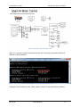
EXPERIMENT #3: Develop Communication Program with Target
and Display Sensors
Objectives
You should develop a cqstreamclient class to receive and display data of sensors of the Qball.
Diagram
Figure 17: The experiment #3 setup
Lab description
Turn on the qball and check that it is connected the workstation as you did in first experiment.
Run matlab/ simulink and open the qball_motor_control simulink model developed in first
experiment. After you load and compile it into the qball, it sends the sensors data via wireless
connection to the qstream clients. To receive and display these data you need to develop a
cqstreamclient class to connect the qstream server on the qball side and receive the data. The
qstreamserver listens to TCP/IP port 18000 and sends sensors data every 5 msec. The data sent
by server is an array of 12 doubles and it is formatted as follows:
Table 3: The qstream sensors data format
Array index
0
1
2
3
4
5
6
7
8
9
42
Sensor description
Gyroscope x-axis
Gyroscope y-axis
Gyroscope z-axis
Accelerometer x-axis
Accelerometer y-axis
Accelerometer z-axis
Magnetometer x-axis
Magnetometer y-axis
Magnetometer z-axis
Battery voltage (V-10)/10
ECE-LAB-RT-02
2014.12.18
The Department of ECE
ECE Real-time System Laboratory
10
11
Sonar
Reserved
You can use following sample codes to implement your code. Please make sure you add
“socket” library in the library list of IDE or use the -l socket option to qcc to link against this
library as it explained in experiment 2.
List 1: ctimer.h
#ifndef CTIMER_H_
#define CTIMER_H_
#include <stdio.h>
#include <iostream.h>
#include <time.h>
#include <errno.h>
#include <unistd.h>
#include <pthread.h>
#include <sync.h>
#include <sys/siginfo.h>
#include <sys/neutrino.h>
#include <sys/netmgr.h>
#include <sys/syspage.h>
#include <inttypes.h>
//=============================================================================
class ctimer
{
private:
int chid;
//channel id
int coid;
//connection back to channel
char msgbuf[100];
//Message msg;
struct sigevent event; //event to deliver
struct itimerspec itime; //timer's data struct
timer_t timer_id;
//timer's ID for the timer
uint64_t cps;
// number of cycles per second
uint64_t tick_cycles, tock_cycles;
public:
int errdisp; // indicates that the error messages needed to be displayed or not
int debugdisp; // indicates that the debug messages needed to be displayed or not
};
ctimer(int sec,int msec);
~ctimer();
void settimer(long seconds, long nanoseconds);
void wait();
void tick();
double tock();
#endif /*CTIMER_H_*/
List 2:ctimer.cpp
2014.12.18
ECE-LAB-RT-02
43
// standard needed header files.
#include "ctimer.h"
// macro definition for error output
#define errcout if(errdisp) cout
// macro definition for debug output
#define debugcout if(debugdisp) cout
using namespace std;
ctimer::ctimer(int sec,int msec)
{
int nanosec;
errdisp=1;
// to display the errors set it to 1; otherwise set it to 0
debugdisp=0;
// to display the debug prompts set it to 1; otherwise set it to 0
nanosec=1000000*msec;
// create a channel
chid = ChannelCreate(0);
coid = ConnectAttach(0,0, chid,0,0); //Attach timer to our channel
if (coid == -1)
{
errcout << "Timer: ConnectAttach ERROR :(" << endl;
//exit(EXIT_FAILURE);
}
//initialization macro of the sigevent:"event" structure
SIGEV_PULSE_INIT(&event, coid, SIGEV_PULSE_PRIO_INHERIT, 1, 0);
debugcout << "TIMER pulse initiated" << endl;
//create timer
//if (timer_create(CLOCK_REALTIME, &event, &timer_id) == -1)
if (timer_create(CLOCK_REALTIME, &event, &timer_id) == -1)
debugcout << " timer_create ERROR"<< endl;
// setting the timer
settimer(sec,nanosec);
}
// find out how many cycles per second
cps = SYSPAGE_ENTRY(qtime)->cycles_per_sec;
ctimer::~ctimer()
{
ChannelDestroy(chid);
debugcout << "TIMER Destructor called" << endl;
}
void ctimer::settimer(long seconds, long nanoseconds)
{
//Will receive pulse initially (the itime.it_value) and every
//(the itime.it_interval)seconds thereafter
itime.it_value.tv_sec = seconds;
44
ECE-LAB-RT-02
2014.12.18
The Department of ECE
}
ECE Real-time System Laboratory
itime.it_value.tv_nsec = nanoseconds;
itime.it_interval.tv_sec = seconds;
itime.it_interval.tv_nsec = nanoseconds;
timer_settime(timer_id, 0, &itime, NULL); //0 for relative time
void ctimer::wait(){ // Wait for timer tick
int rcvid;
rcvid = MsgReceive(chid, &msgbuf, sizeof(msgbuf), NULL);
}
void ctimer::tick(){
// snap the time
tick_cycles=ClockCycles( );
}
double ctimer::tock(){
// snap the time
tock_cycles=ClockCycles( );
return (double)((int)(((double)(tock_cycles-tick_cycles)/cps)*100000))/100;
}
List 3: cqstreamclient.h
#ifndef CQSTREAMCLIENT_H_
#define CQSTREAMCLIENT_H_
#include <pthread.h>
class cqstreamclient{
private:
pthread_t thread_id;
pthread_mutex_t mutex;
int stop_req;
double rcv_data[100];
bool is_data_copied2buff, is_data_sent;
friend void * thread_stud(void* arg);
public:
int port;
int sample_time;
int ch_size;
char hostaddress[200];
csocket s;
cqstreamclient(char * hostaddress, int port,int sample_time,int ch_size);
~cqstreamclient();
int new_data_is_sent();
void get_data_array(double * databuff);
double get_data(int i);
void stop();
void start();
void client();
};
2014.12.18
ECE-LAB-RT-02
45
#endif /*CQSTREAMCLIENT_H_*/
List 4: cqstreamclient.cpp
//===========================================================================
// standard needed header files.
#include <string.h>
#include <iostream.h>
#include "csocket.h"
#include "ctimer.h"
#include "cqstreamclient.h"
using namespace std;
cqstreamclient::cqstreamclient(char * hostaddress, int port,int sample_time,int ch_size){
this->port=port;
this->sample_time=sample_time;
this->ch_size=ch_size;
strcpy(this->hostaddress,hostaddress);
}
thread_id=NULL;
pthread_mutex_init(&mutex,NULL);
start();
cqstreamclient::~cqstreamclient(){
stop();
pthread_mutex_destroy(&mutex);
}
void cqstreamclient::start(){
int i;
stop_req=0;
for(i=0;i<ch_size;i++) rcv_data[i]=0;
}
if(pthread_create(&thread_id,NULL,thread_stud,(void *) this)!=EOK)
thread_id=NULL;
void cqstreamclient::stop(){
stop_req=1;
if(thread_id != NULL)
pthread_join(thread_id,NULL);
thread_id=NULL;
}
void cqstreamclient::get_data_array(double * databuff){
pthread_mutex_lock(&mutex);
// copy the data from rcv_data to the output buffer
pthread_mutex_unlock(&mutex);
46
ECE-LAB-RT-02
2014.12.18
The Department of ECE
ECE Real-time System Laboratory
}
double cqstreamclient::get_data(int i){
pthread_mutex_lock(&mutex);
// return the from rcv_data
pthread_mutex_unlock(&mutex);
}
void * thread_stud(void* arg){
cqstreamclient& qstream = *(cqstreamclient *) arg;
qstream.client();
return 0;
}
#define BUFLEN 1000
void cqstreamclient::client(){
int rcv_data_size=0,timeoutcnt=0;
// initiate the timer
while( stop_req==0){
// initialize the socket and connect to server
cout<<"Connected to the server."<<endl;
timeoutcnt=0;
while( stop_req==0){
// receiving the data
/* if data is received {
timeoutcnt=0;
pthread_mutex_lock(& mutex);
copy data to rcv_data buffer
pthread_mutex_unlock(& mutex);
} else timeoutcnt++;*/
if(rcvlen==-1 || timeoutcnt>100) break; // there is an
//wait for the timer
}
}
}
// close the socket
Check points
Your performance in this lab will be evaluated based on the following operations properly being
implemented.
- Develop cqstreamclient class
- Connect to the qball qsreamserver
- Receive and display the sensors value every 5 msec.
2014.12.18
ECE-LAB-RT-02
47
EXPERIMENT #4: Joystick Interface
Objectives
Develop a driver for joystick and build a cjoystick class
Readback the joystick X,Y,Z and RZ data and display the data
Diagram
Figure 18: The experiment #4 setup
Lab description
To read the joystick data you should use Qnx HID interface APIs. Therefore please please make
sure you add “hiddi” library in the library list of IDE or use the -l hiddi option to qcc to link
against this library before you start your work. To add a library in IDE open the project>properties menu as shown in figure 2.
In the opened dialog box select “QNX C/C++ Project” in the left side, and then, goto “Linker”
and select “Extra libraries” in the “Category” combo box. Click on “Add” button and add “hiddi”
in the list as shown in figure 3.
48
ECE-LAB-RT-02
2014.12.18
The Department of ECE
ECE Real-time System Laboratory
The class cjoystick should provide an interface to the XFX Game Controller (Vendor ID: 0x0E8F
and PRODUCT_ID: 0x0003) USB HID compliant joysticks:To use the joystick please ensure that
the USB manager (devu-uhci or devu-ohci) and manager for HID devices (io-hid) are running.
You will need to be root to use this class. Here are the commands to start the device managers
(as root) :
/sbin/devu-uhci & (or /sbin/devu-ohci &)
/sbin/io-hid &
mount -Tio-hid devh-usb.so &
You can use following sample codes to implement your code. Please note that range of data
sent by joystick is between 0x25 and 0xC4 and you should rescale it in the range of -1 and 1.
List 1: cjoystick.h
//========================================================================
// cjoystick.hpp : XFX Game Controller HID Joystick Interface
//
Version 1.0
//
// Author
: Vilas Kumar Chitrakaran <[email protected]>
// Author
: Vilas Kumar Chitrakaran <[email protected]>
// Modified by
: Iman Saboori
// Date
: June 2011
//========================================================================
#ifndef _CJOYSTICK_HPP_INCLUDED
#define _CJOYSTICK_HPP_INCLUDED
2014.12.18
ECE-LAB-RT-02
49
#include <sys/hiddi.h>
//========================================================================
/*! \struct joystick_data
\brief A structure for holding joystick data */
//========================================================================
typedef struct joystick_data
{
bool status_flag;
//!< 'true' if device status is OK.
char status_msg_buff[80]; //!< Char buffer to hold device status message.
int x;
int y;
int z;
int rx;
int ry;
int rz;
}joystick_data_t;
//========================================================================
/*! \struct joystick_report
\brief A structure for device reports (for driver internal use) */
//========================================================================
typedef struct joystick_report
{
struct hidd_report_instance *creport_instance;
struct hidd_report
*creport;
_uint16
*cbtnbuf; // current button buffer
}joystick_report_t;
//========================================================================
/*! \struct joystick_device
\brief A structure for joystick devices (for driver internal use) */
//========================================================================
typedef struct joystick_device
{
joystick_data_t
data;
//!< device current data.
joystick_report_t
*report;
hidd_device_instance_t *device_instance;
}joystick_device_t;
//========================================================================
class cjoystick
{
public:
cjoystick();
// The default constructor. Establishes connection with the HID driver.
// devNum The address of the joystick device to connect to (default = 0).
~cjoystick();
// The default destructor disconnects from the HID driver and cleans up.
50
ECE-LAB-RT-02
2014.12.18
The Department of ECE
ECE Real-time System Laboratory
int getX() const;
// return The X position
int getY() const;
// return The Y position
int getZ() const;
// return The Y position
int getRX() const;
// return The Y position
int getRY() const;
// return The Y position
int getRZ() const;
// return The Y position
bool is_status_ok() const;
// return true if no error, else false.
char *get_status_msg() const;
// return A string carrying current status of the device. This string
//
also carries error messages when is_status_ok() returns false.
void print_device_info(int verbosity = 1) const;
// Print information about the device to stdout. Higher values of
// \a verbosity mean more detailed information.
protected:
joystick_data_t get_joystick_data() const;
// return The whole data structure for device
//
with current joystick data
private:
struct hidd_connection *d_connection;
// connection handle to HID server
// ----- HID server connection functions -----static joystick_device_t s_joystick;
static void on_insertion(struct hidd_connection *connection, hidd_device_instance_t *instance);
static void on_removal(struct hidd_connection *connection, hidd_device_instance_t *instance);
static void on_hid_report(struct hidd_connection *connection, struct hidd_report *handle,
void *report_data, _uint32 report_len, _uint32 flags, void *user);
};
#endif // #ifndef _CJOYSTICK_HPP_INCLUDED
2014.12.18
ECE-LAB-RT-02
51
List 2: cjoystick.cpp
//========================================================================
// cjoystick.cpp : XFX Game Controller HID Joystick Interface
//
Version 1.0
//
// Author
: Vilas Kumar Chitrakaran <[email protected]>
// Modified by
: Iman Saboori
// Date
: 11 June 2011
//========================================================================
#include "cjoystick.h"
#include <sys/hidut.h>
#include <sys/hiddi.h>
#include <unistd.h>
#include <iostream.h>
#include <errno.h>
#include <string.h>
#include <stdio.h>
#include <stdlib.h>
#define HID_VENDOR_XFX
#define HID_PRODUCT_XFX
0x0E8F
0x0003
#define JOYSTICK_MIN_VAL 0x25
#define JOYSTICK_MAX_VAL 0xC4
joystick_device_t cjoystick::s_joystick;
//========================================================================
// cjoystick::cjoystick
//========================================================================
cjoystick::cjoystick()
{
s_joystick.data.status_flag = true;
strncpy(s_joystick.data.status_msg_buff, "cjoystick : not initialized", 80);
d_connection = NULL;
s_joystick.device_instance = NULL;
if (geteuid() != 0)
{
s_joystick.data.status_flag = false;
strncpy(s_joystick.data.status_msg_buff,
"cjoystick : Requires superuser privileges", 80);
return;
}
hidd_device_ident_t interest = {HID_VENDOR_XFX,
HIDD_CONNECT_WILDCARD /* HID_PRODUCT_XFX */,
(_uint32)HIDD_CONNECT_WILDCARD /* HID_VERSION */};
52
ECE-LAB-RT-02
2014.12.18
The Department of ECE
ECE Real-time System Laboratory
hidd_funcs_t funcs = {_HIDDI_NFUNCS,
on_insertion,
on_removal,
on_hid_report,
NULL};
hidd_connect_parm_t parm = {NULL,
HID_VERSION,
HIDD_VERSION,
0,
0,
&interest,
&funcs,
HIDD_CONNECT_WAIT};
if ( hidd_connect(&parm, &d_connection) != EOK )
{
s_joystick.data.status_flag = false;
strncpy(s_joystick.data.status_msg_buff,
"cjoystick : Connection with HID driver failed: ", 80);
strncat(s_joystick.data.status_msg_buff, strerror(errno),
80 - strlen(s_joystick.data.status_msg_buff));
return;
}
strncpy(s_joystick.data.status_msg_buff,
"cjoystick : Waiting for Joystick", 80);
}
//========================================================================
// cjoystick::~cjoystick
//========================================================================
cjoystick::~cjoystick()
{
if(d_connection)
hidd_disconnect( d_connection );
}
//========================================================================
// cjoystick::getX()
//========================================================================
int cjoystick::getX() const
{
// return X-axis value
}
//========================================================================
// cjoystick::getY()
//========================================================================
int cjoystick::getY() const
{
// return Y-axis value
}
2014.12.18
ECE-LAB-RT-02
53
//========================================================================
// cjoystick::getZ()
//========================================================================
int cjoystick::getZ() const
{
// return Z-axis value
}
//========================================================================
// cjoystick::getRX()
//========================================================================
int cjoystick::getRX() const
{
// return RX-axis value
}
//========================================================================
// cjoystick::getRY()
//========================================================================
int cjoystick::getRY() const
{
// return RY-axis value
}
//========================================================================
// cjoystick::getRZ()
//========================================================================
int cjoystick::getRZ() const
{
// return RZ-axis value
}
//========================================================================
// cjoystick::is_status_ok()
//========================================================================
bool cjoystick::is_status_ok() const
{
return s_joystick.data.status_flag;
}
//========================================================================
// cjoystick::get_status_msg()
//========================================================================
char * cjoystick::get_status_msg() const
{
return (char *)s_joystick.data.status_msg_buff;
}
//========================================================================
// cjoystick::print_device_info
//========================================================================
void cjoystick::print_device_info(int verbosity) const
54
ECE-LAB-RT-02
2014.12.18
The Department of ECE
ECE Real-time System Laboratory
{
hidd_device_instance_t *device_instance =
s_joystick.device_instance;
if(device_instance == NULL)
return;
char buffer[100];
hidd_get_manufacturer_string(d_connection, device_instance, buffer, 100);
cout << "Manufacturer : " << buffer << endl;
hidd_get_product_string(d_connection, device_instance, buffer, 100);
cout << "Product
: " << buffer << endl;
if(verbosity < 2)
return;
cout << "Software Version : 1.0, June 2011" << endl;
cout << "Status message : " << s_joystick.data.status_msg_buff << endl;
}
//========================================================================
// cjoystick::get_joystick_data
//========================================================================
joystick_data_t cjoystick::get_joystick_data() const
{
return s_joystick.data;
}
//========================================================================
// cjoystick::on_insertion
//========================================================================
void cjoystick::on_insertion(struct hidd_connection *connection,
hidd_device_instance_t *device_instance)
{
struct hidd_collection **hidd_collections, **hidd_mcollections, **hidd_ncollections;
struct hidd_report_instance *report_instance;
struct hidd_report *report;
joystick_report_t *jstk_report = NULL;
_uint16 num_col, num_mcol, num_ncol;
_uint16 usage_page, usage;
_uint16 max_but=0;
int i;
s_joystick.device_instance = device_instance;
// Get root level HID collections
hidd_get_collections( device_instance, NULL, &hidd_collections, &num_col);
// for each top level collection
for(i = 0; i < num_col; i++)
{
// Get usage for the collection
hidd_collection_usage( hidd_collections[i], &usage_page, &usage);
2014.12.18
ECE-LAB-RT-02
55
// Ignore collection if it doesn't describe joystick functionality
if( usage_page != HIDD_PAGE_DESKTOP || usage != HIDD_USAGE_JOYSTICK)
continue;
if( hidd_get_report_instance(hidd_collections[i], 0, HID_INPUT_REPORT,
&report_instance) == EOK )
{
hidd_num_buttons( report_instance, &max_but );
if( hidd_report_attach( connection, device_instance, report_instance, 0,
sizeof(joystick_report_t) + (max_but * sizeof(_int32)) , &report ) == EOK )
{
jstk_report = (joystick_report_t *)hidd_report_extra( report );
jstk_report->creport = report;
jstk_report->creport_instance = report_instance;
jstk_report->cbtnbuf = (_uint16 *) (jstk_report + 1); // setup pointer to button data
s_joystick.report = jstk_report;
break;
}
}
// *** The following is a bad hack. Fix it as recursive search for report ****
hidd_get_collections( NULL, hidd_collections[i], &hidd_mcollections, &num_mcol);
if ( num_col && hidd_get_report_instance( hidd_mcollections[0], 0 , HID_INPUT_REPORT,
&report_instance ) == EOK )
{
hidd_num_buttons( report_instance, &max_but );
if( hidd_report_attach( connection, device_instance, report_instance, 0,
sizeof(joystick_report_t) + (max_but * sizeof(_int32)) , &report ) == EOK )
{
jstk_report = (joystick_report_t *)hidd_report_extra( report );
jstk_report->creport = report;
jstk_report->creport_instance = report_instance;
jstk_report->cbtnbuf = (_uint16 *) (jstk_report + 1); // setup pointer to button data
s_joystick.report = jstk_report;
break;
}
}
hidd_get_collections( NULL, hidd_mcollections[i], &hidd_ncollections, &num_ncol);
if ( num_mcol && hidd_get_report_instance( hidd_ncollections[0], 0 , HID_INPUT_REPORT,
&report_instance ) == EOK )
{
hidd_num_buttons( report_instance, &max_but );
if( hidd_report_attach( connection, device_instance, report_instance, 0,
sizeof(joystick_report_t) + (max_but * sizeof(_int32)) , &report ) == EOK )
{
jstk_report = (joystick_report_t *)hidd_report_extra( report );
jstk_report->creport = report;
jstk_report->creport_instance = report_instance;
56
ECE-LAB-RT-02
2014.12.18
The Department of ECE
ECE Real-time System Laboratory
jstk_report->cbtnbuf = (_uint16 *) (jstk_report + 1); // setup pointer to button data
s_joystick.report = jstk_report;
break;
}
}
} // end for
s_joystick.data.status_flag = true;
strncpy(s_joystick.data.status_msg_buff,
"cjoystick : Joystick present", 80);
}
//========================================================================
// cjoystick::on_removal
//========================================================================
void cjoystick::on_removal(struct hidd_connection *connection,
hidd_device_instance_t *instance)
{
hidd_reports_detach( connection, instance);
s_joystick.data.status_flag = true;
strncpy(s_joystick.data.status_msg_buff,
"cjoystick : Joystick unplugged", 80);
}
//========================================================================
// cjoystick::on_hid_report
//========================================================================
void cjoystick::on_hid_report(struct hidd_connection *connection,
struct hidd_report *handle, void *report_data,
_uint32 report_len, _uint32 flags, void *user)
{
_uint32 xval, yval, zval, rxval, ryval, rzval;
struct hidd_collection
*collection;
struct hidd_report_instance *report_instance;
report_instance = s_joystick.report->creport_instance;
hidd_report_collection( report_instance, &collection );
// Read the joystick data
// hidd_get_usage_value( report_instance, NULL, HIDD_PAGE_DESKTOP, HIDD_USAGE_X, report_data,
&xval);
}
Check points
Your performance in this lab will be evaluated based on the following operations properly being
implemented.
Read the joystick data and display the X,Y,Z and RZ values
2014.12.18
ECE-LAB-RT-02
57
EXPERIMENT#5: Maneovue Qball by Joystick
Objectives
-
Use ctimer class and cjoystick class to readback the joystick X,Y,Z and RZ data
Develop a cqstreamsrv class to send the joystick data to qball
Use ctimer class and cqstreamclient class to read the qball sensors and diplay it
Use qball_motor_control Simulink model to send the sensors data to SPC and receive
commands from SPC to control the motors speeds.
Diagram
Figure 19: The experiment #5 setup
Lab description
In this experiment you should all the classes which are developed in the last experiments
should be used to control the speed of qball propellers using the joystick. Turn on the qball and
check that it is connected the workstation as you did in first experiment. Run matlab/ simulink
and open the qball_motor_control simulink model developed in first experiment. After you load
and compile it into the qball, it sends the sensors data via wireless connection to the qstream
clients. Use cqstreamclient class to connect to qstream server on qball at TCP/IP port 18000 and
read and display sensors data every 5 msec. Use cjoystick class to read joystick data and
develop a cqstreamsrv class to send the joystick data to the qball every 5 msec. The
cqstreamsrv class should bind to TCP/IP port 18005 and accept the connection requests from
the qstream client on the qball side. The data sent by server should be an array of 8 doubles
and it is formatted as follows:
Table 4: cqstreammsrv data format
Array index
0
1
2
3
58
Data description
Joystick X-axis
Joystick Y-axis
Joystick Z-axis
Joystick RZ-axis
ECE-LAB-RT-02
2014.12.18
The Department of ECE
ECE Real-time System Laboratory
4
5
6
7
0
0
0
0
List 1: cqstreamsrv.h
#ifndef CQSTREAMSRV_H_
#define CQSTREAMSRV_H_
#include <pthread.h>
class cqstreamsrv{
private:
pthread_t thread_id;
pthread_mutex_t mutex;
int stop_req;
double snd_data[8];
bool is_data_copied2buff, is_data_sent;
friend void * thread_stud_srv(void* arg);
public:
d6,double d7);
};
int port;
int sample_time;
csocket s;
cqstreamsrv(int port,int sample_time);
~cqstreamsrv();
int new_data_is_sent();
void send_data_array(double data[]);
void send_data(double d0,double d1,double d2,double d3,double d4,double d5,double
void stop();
void start();
void server();
#endif /*CQSTREAMSRV_H_*/
List2: cqstreamsrv.cpp
// standard needed header files.
#include <string.h>
#include <iostream.h>
#include "csocket.h"
#include "ctimer.h"
#include "cqstreamsrv.h"
using namespace std;
cqstreamsrv::cqstreamsrv(int port,int sample_time){
2014.12.18
ECE-LAB-RT-02
59
}
this->port=port;
this->sample_time=sample_time;
thread_id=NULL;
pthread_mutex_init(&mutex,NULL);
start();
cqstreamsrv::~cqstreamsrv(){
stop();
pthread_mutex_destroy(&mutex);
}
void cqstreamsrv::start(){
int i;
stop_req=0;
is_data_copied2buff=false;
is_data_sent=false;
for(i=0;i<8;i++) snd_data[i]=0;
if(pthread_create(&thread_id,NULL,thread_stud_srv,(void *) this)!=EOK)
thread_id=NULL;
}
void cqstreamsrv::stop(){
stop_req=1;
if(thread_id != NULL)
pthread_join(thread_id,NULL);
thread_id=NULL;
}
void cqstreamsrv::send_data_array(double data[]){
pthread_mutex_lock(&mutex);
//copy data to the buffer
is_data_copied2buff=false;
pthread_mutex_unlock(&mutex);
}
void cqstreamsrv::send_data(double d0,double d1,double d2,double d3,double d4,double d5,double
d6,double d7){
pthread_mutex_lock(&mutex);
//copy data to the buffer
is_data_copied2buff=false;
pthread_mutex_unlock(&mutex);
}
int cqstreamsrv::new_data_is_sent(){
if(is_data_sent && is_data_copied2buff)
return 1;
else
return 0;
}
void * thread_stud_srv(void* arg){
60
ECE-LAB-RT-02
2014.12.18
The Department of ECE
}
ECE Real-time System Laboratory
cqstreamsrv& qstream = *(cqstreamsrv *) arg;
qstream.server();
return 0;
void cqstreamsrv::server(){
// initiate the timer
while( stop_req==0){
// initialize the socket and bind to the port
}
while( stop_req==0){
// start listening to the port
}
while( stop_req==0){
while( stop_req==0){
// accepts the client request
}
while( stop_req==0){
pthread_mutex_lock(& mutex);
//copy snd_data to the local buffer
is_data_copied2buff=true;
is_data_sent=false;
pthread_mutex_unlock(& mutex);
//send local buffers data
pthread_mutex_lock(& mutex);
is_data_sent=true;
pthread_mutex_unlock(& mutex);
// wait for timer
}
}
}
// close the socket
Check points
Your performance in this lab will be evaluated based on the following operations properly being
implemented.
Receive and display the received data
2014.12.18
ECE-LAB-RT-02
61
4. TEMPLATE FOR LAB REPORTS
Page 1 - Cover Page
Include: Lab number, Lab Title, Student name(s), Student ID(s), Team ID, Workstation ID,
Due date.
Page 2 - Contributions by each member
In one page (about 1 paragraph per person), explain what work each team member
accomplished.
Pages 3 to n, (where n <= 15)
1. Objective:
In two or three sentences, state the objectives of the lab experiment.
2. Introduction:
Introduce the experiment in three parts:
2.1 Background: Provide any necessary background information about the experiment so
that someone outside of the class, who hasn’t read your previous work, can understand
your context.
2.2 Approach: Give an overview of how you intend on meeting the objectives stated in
section 1.
2.3 Requirements: In your own words (i.e. don’t just copy from the lab manual), state what
the requirements of the experiment are. Prioritize them.
3. Analysis:
Write a page or two discussing what to do exactly. Detail your understanding of the
requirements, or how you interpret them. What does your interpretation imply? Use-Case
Diagrams (with natural language descriptions) and scenarios may help.
4. Design:
Write two or three pages discussing how you plan to solve the problem. Describe any
algorithms or important procedures. A detailed Class Diagram (with attributes and
methods), Interaction Diagrams, State Diagrams, or Activity Diagrams may be necessary to
explain your design.
5. Implementation:
In a tabular format, say what was implemented, what was partly implemented, and what
was not implemented. Also state if you were able to test each item, and if it passed or failed
the test. It would be a good idea to describe the test too. Your requirements listed in the
table will come from section 2.3 and section 3 of your report
You should also discuss any problems encountered, or why you were not able to implement
features to satisfy all the requirements of the experiment. State whether these problems
are solvable and how?
6. Future Work:
In one or two paragraphs, describe what your future project plans are and how the work
accomplished in this experiment fits into the picture.
7. Answers to Lab Manual Questions:
Answer the questions in the lab manual here.
8. Lessons Learned:
62
ECE-LAB-RT-02
2014.12.18
The Department of ECE
ECE Real-time System Laboratory
What did you learn? What would you do differently next time?
9. Conclusion:
Briefly summarize your results (successes and otherwise). Highlight what was the most
important concept(s) or issue(s) that you dealt with. Give a brief statement related to future
work.
2014.12.18
ECE-LAB-RT-02
63
5. FAQs
Which accounts do I have in the real-time lab?
Normally you will have a personal real-time account for developing real-time program.
And you can also have a testing account on QNX SBCs to run your final application. You
can save your files or data to your ENCS /homes or Real-time home.
How to restore my password?
If you forgot your real-time password, you can send email to Danli@ece for help.
Can I install some application tools on the workstations?
No!
Where to get the door code? Or Can I come to the lab alone?
Real-time system lab is a supervised lab. It won’t be allowed for any student to come
the lab without any supervision. If you can’t finish the work in your section, you may
have to contact your TA for the extra section.
64
ECE-LAB-RT-02
2014.12.18