1
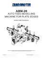
ABM-28
AUTO FEED BEVELLING
MACHINE FOR PLATE EDGES
OPERATOR’S MANUAL
BEFORE USE, ENSURE EVERYONE USING THIS MACHINE READS AND UNDERSTANDS
ALL SAFETY AND OPERATING INSTRUCTIONS IN THIS MANUAL .
Serial #............................................
Date of Purchase............................
TRADEMASTER ABM-28 AUTO FEED BEVELLING MACHINE
IMPORTED & DISTRIBUTED BY
INDUSTRIAL TOOL & MACHINERY SALES
INDUSTRIAL TOOL
T
F
E
W
18 BUSINESS ST
YATALA QLD 4207 AUSTRALIA
07 3287 1114
07 3287 1115
[email protected]
www.industrialtool.com.au
WARRANTY TERMS
In addition to any warranties or conditions implied by applicable Statute or Regulations, Industrial
Tool & Machinery Sales warrants all of it’s products against defective workmanship and faulty
materials for a period of twelve (12) months from the date of purchase, unless otherwise stated.
At our option we will repair or replace, free of charge, any item on the condition that:
• The complete machine or tool is returned, freight prepaid to ITM or one of it’s authorised
service agents as directed by ITM, and is found to have a material or constructional defect.
• The machine or tool has not been subject to misuse, neglect or damage by accident.
• The fault is not a result of normal “wear and tear”.
• Written permission has been received from ITM prior to commencement of repair.
• Repairs, tampering or modification carried out by unauthorised personnel will void all warranty.
• Consumable items such as cutting tools, pilot pins, saw blades, grinding wheels etc. are NOT
covered by warranty.
Our goods come with guarantees which cannot be excluded under the Australian Consumer
Law. You are entitled to replacement or refund for a major failure and to compensation for other
reasonably foreseeable loss or damage. You are also entitled to have the goods repaired or
replaced if the goods fail to be of acceptable quality and the failure does not amount to a major
failure.
2
TRADEMASTER ABM-28 AUTO FEED BEVELLING MACHINE
TABLE OF CONTENTS
1.
1.1.
1.2.
Safety Instructions
Application
Safety Requirements
-4-4-4-
2.
2.1.
2.2.
2.3.
Technical Data
Design
Equipment Included
Optional Equipment
-6-7-9-9-
3.
3.1.
3.2.
3.3.
3.4.
3.5.
3.6.
Start Up & Operation
Preparation
Setting Bevel Parameters
Usage
Replacing Cutting Inserts
Replacing Milling Head
Replacing Milling Unit Support
- 10 - 10 - 12 - 13 - 14 - 15 - 16 -
4.
Wiring Diagram
- 17 -
5.
Spare & Wearing Parts
- 18 -
3
SAFETY INSTRUCTIONS
READ OPERATOR’S MANUAL BEFORE YOU
START TO WORK WITH THE MACHINE.
1. Safety Instructions
The ABM-28 auto feed bevelling machine should be used only to applications stated in the manual.
Using in other applications may lead to personal injury and machine damage.
1.1. Application
The ABM-28 bevelling machine is designed for milling edges of plates with the thickness up to
35 mm (1.38’’). The bevelling angle can be set continuously between 60° and –60°, including
facing at 0°. The feed is performed automatically after starting by the operator. Using optional
equipment enables you to establish J-bevels or to bevel 35-70 mm (1.38–2.76’’) thick plates at
the continuously set angle between 0° and 60° or between 0° and –60°.
1.2. Safety Requirements
Using beveller is not allowed if:
1. The operator has not read the Operator’s Manual or has not completed proper occupational
safety and health training.
2. Machine is to be used in applications not stated in Operator’s Manual
3. Machine is not complete or parts used for repair are not genuine.
4. Power supply specifications do not conform to those stated on rating plate.
5. Operator has not checked condition of machine, including power cord, control panel
components and milling tools.
6. Machined pipe is not properly secured from falling or rolling.
7. Bystanders are present in immediate vicinity of machine.
Detailed safety rules:
8.
9.
10.
11.
12.
13.
14.
15.
16.
17.
18.
4
Before starting, read this Operator’s Manual and complete proper occupational safety and
health training.
Machine must be used only in applications stated in Operator’s Manual.
Machine must be complete and all parts must be genuine and fully operational.
Power supply specifications must conform to those stated on rating plate.
Power supply socket must be equipped with grounding pin.
Never carry machine by cord or yank it to disconnect plug from socket. It may cause power
cord to break and result in electric shock.
Untrained bystanders must not be present near machine.
Before starting, check condition of machine and electrical installation, including power cord,
plug, control components, and milling tools.
Check presence of protective bolts at both guide ends.
Keep machine dry. Exposing it to rain, snow, or frost is prohibited.
Keep work area clean and well lit.
SAFETY INSTRUCTIONS
19.
20.
21.
22.
23.
24.
25.
26.
27.
28.
29.
30.
31.
32.
Never use machine in vicinity of flammable fluids or gases, or in explosive environments.
Never use blunt or damaged tools.
Use only tools recommended by manufacturer and specified in Operator’s Manual.
Mount cutting inserts and milling head securely. Remove adjusting keys and wrenches from
work area before connecting plug to power socket.
If cutting edge of insert is worn out, rotate insert in socket by 90° or, if all edges are worn out,
replace with new insert specified in Operator’s Manual.
Before every use, inspect machine to ensure it is not damaged. Check whether any part
is cracked or improperly fitted. Make sure to maintain proper conditions that may affect
machine operation.
Always use safety goggles, hearing protection, protective shoes, and protective clothing
during operation. Do not wear loose clothing.
Do not touch moving parts or metal chips formed during milling. Prevent objects from being
caught in moving parts.
After every use, remove metal chips from machine, particularly from milling head. Never
remove metal chips with bare hands.
Carry chips container using handles.
Maintain machine and tools with care. Cover steel parts with thin grease layer to protect
them against rust when not in use for a longer period.
Perform all maintenance work only with power cord unplugged from power socket.
Perform all repairs only in service centre appointed by seller.
If machine falls on hard surface, from height, is wet, or has other damage that could affect
technical state of machine, stop operation and immediately send machine to service centre
for inspection.
WARNING! SAFETY RULES MUST BE CLOSELY OBSERVED.
5
TECHNICAL DATA
2. Technical Data
1211 mm (47.7’’)
619 mm (24.4’’)
532 mm (20.9’’)
Voltage
Power
Rotational speed (without load)
Protection level
Protection class
Bevel angle
Maximum bevel width
Minimum plate thickness
Weight
6
~ 220–240 V, 50–60 Hz
1600 W
2780 min-1
IP 20
class I
60 to –60° (ß, Figure 1)
35 mm (b, Figure 1, Table 1)
10 mm
78.5 kg (173 lbs)
TECHNICAL DATA
Figure 1. Bevel dimensions
b
0°
35 mm
30°
30 mm
45°
28 mm
60°
30 mm
Table 1. Maximum bevel width depending on the angle
2.1. Design
The ABM-28 bevelling machine consists of a milling unit, milling unit support, guide, carriage
for moving the milling unit along the guide, two movable clamps for mounting a plate, and
three set blocks for positioning and mounting the guide to the plate. Detailed design is
shown in Figure 2.
7
TECHNICAL DATA
protecƟve bolt
travel direcƟon switch
emergency switch
guide
segment
speed adjusƟng knob
supply socket for
milling unit
motor ON switch
overload lamp
motor OFF switch
carrying handle
power ON/OFF switch
A
protecƟve bolt
chips
clamping
lever
chips container
bevel depth
indicator
bevel angle
pitch
container handle
milling
head
bevel depth
it h
adjusƟng bolt
clamping rod
A
bevel depth
lock lever
bevel angle
lock lever
container bracket
spindle lock buƩon
bevel angle
lock lever
bevel depth adjusƟng lever
Figure 2. Machine design
8
TECHNICAL DATA
2.2. Equipment Included
The ABM-28 is supplied in a wooden box with the complete standard equipment. The included
equipment consists of:
•
•
•
•
•
•
•
•
•
•
•
•
•
•
•
•
•
•
wooden box
carriage on a guide
additional guide segment
clamp
set block
milling unit support for
bevelling at –60° to 60°
milling unit
chips container
tools container
4 mm Allen key
5 mm Allen key
6 mm Allen key
8 mm Allen key
13/17 mm flat key
screwdriver for securing cutting inserts
nut, spring washer, round washer for
mounting milling unit support
Terebor oil for steel
Operator’s Manual
– 1 unit
– 1 unit
– 1 unit
– 2 units
– 3 units
– 1 unit
– 1 unit
– 1 unit
– 1 unit
– 1 unit
– 1 unit
– 1 unit
– 1 unit
– 1 unit
– 1 unit
– 2 units
– 1 unit
– 1 unit
2.3. Optional Equipment
You can order the following optional equipment:
WAP-B010
• Replacement cutting tips for hardened steels (10 required)
WAP-B020
• Replacement standard cutting tips (10 required)
WAP-B28/6130
• Lever Clamp for plate up to 35mm thick
WAP-B28/6140
• Lever Clamp for plate up to 70mm thick
WAP-B28/6150
• Positioner unit for plate up to 35mm thick
WAP-B28/6160
• Positioner unit for plate up to 70mm thick
WAP-B28/6170
• Rail segment 1200mm long
WAP-B28/6180
• Milling unit support for bevelling 35-70mm 0 ° to 60°
WAP-B28/6190
• Milling unit support for bevelling 35-70mm 0 ° to -60°
9
START UP & OPERATION
3. Start Up & Operation
WARNING! Read safety precautions before starting.
3.1. Preparation
The carriage set on the guide in the utmost left position must be placed on a plate between
two movable clamps in the manner shown in Figure 3a. If needed, extend the guide length by
connecting additional guide segments and tighten the set screws using a 4 mm Allen key (Figure
3b). Then, mount the protective bolts 1 and 2 at both ends of the guide, and position the guide
using set blocks in a way to align the set blocks with the respective surfaces of the guide and
plate. Mount the set blocks using levers (3, 4, 5) and tighten the clamp screws by rotating the
clamping rods (6, 7). To adjust the pressing force of set blocks depending on plate thickness, use
adjusting screws which can be located in one of the three holes.
a)
b)
1
set screw
9
2
6
10
3
8
4
5
7
Figure.3. Placing machine on plate (a); mounting additional guide segments (b)
10
STARTUP & OPERATION
If the plate is to be machined at a negative angle (from the bottom), loosen the two milling unit
support screws using the 4 mm Allen key, and set the indicator to the value of the plate thickness
(8). Position the milling unit support on the screws (9), place the washers under the nuts (10) in
the order shown in Figure 3, and tighten the nuts using 13 mm flat key.
Connect the milling unit with the bevel depth adjusting lever in utmost left position as in Figure
4 to the support (1), rotate the lever maximally counterclockwise (2), and lock the bevel depth
lock lever (3). If the plate is to be machined at the positive angle (from the top), attach the chips
container to the brackets (4).
1
3
2
4
Figure.4. Method of mounting milling unit
11
START UP & OPERATION
3.2. Setting Bevel Parameters
Loosen the lever 1 (Figure 5) and rotate the lever 2 to set the proper milling head penetration
in working material on the pitch 3 (one graduation equals 1 mm, 0.04’’), and afterward lock the
position using lever 1.
6
1
5
4
3
2
Figure.5. View of milling unit
Then, loosen the levers 4 and 5, and rotate the milling unit in a way to set the bevel angle on the
pitch 6, and afterward lock the levers 4 and 5.
It is recommended to start bevelling with the milling head maximally retracted, especially when
milling at the angle of 0°.
12
START UP & OPERATION
3.3. Usage
Plug the milling unit power cord into the socket 1 (Figure 6), and the plug 2 into power socket.
Then, set the power switch 3 to position “1” and use the knob 4 to change the carriage travel
speed to minimum. Choose right travel direction using the switch 5 and start the motor with the
button 6.
2
1
9
5
4
3
6
7
8
Figure.6. View of control panel
Once the travel is started, set a speed that will ensure sufficient milling performance, while
preventing motor overload and excessive wear of the cutting inserts. Good effects are achieved
with a speed at which the overload lamp 7 will not flash.
The plate must be at every time pressed by two set blocks positioned as close to the current
carriage position as possible. When the carriage gets close to the set block, relocate the block to
the other side of the carriage.
It is recommended to establish bevels in several passes and to not exceed 4 mm (0.16’’) of the
milling head penetration (Figure 1) in a single pass. When the carriage reaches the plate end,
toggle the switch 5 to the opposite travel direction or first stop the carriage with the button 8
and then readjust the bevel depth or angle. Once the bevelling is finished, perform the finishing
machining by travelling the carriage with minimal milling head penetration and without using the
set blocks.
In an emergency, use the emergency switch 9 to shut down the power. In such case, to restart
the operation, remove the cause of the shutdown, unlock the emergency switch, and start the
machine using the button 6.
13
START UP & OPERATION
If the speed is too high for the set bevel width and depth, the machine will cyclically stop and start.
In such case, decrease the travel speed or milling head penetration in the workpiece.
If the machine becomes overloaded, e.g. when the bevel width is too large for the material being
machined, when the cutting inserts are blunt, or when the carriage travel speed and bevel depth
are too high, the spindle will automatically stop. In such case, press and hold the button 6, which
will travel the carriage in the opposite direction and will enable the operator to retract the milling
head from the workpiece. Then, release the button 6, press the button 8, and after removing the
cause of the shutdown, restart the motor using the button 6.
If the carriage stops due to reaching one of the protective bolts, toggle to the opposite travel
direction using the switch 5 before restarting.
Operating with the maximum permitted load (flashing of the overload lamp) is allowed, but the
motor temperature must not exceed 85°C (185°F). This type of motor can work under high
temperatures, but long-lasting overheating can permanently damage its windings. Therefore,
after longer working under full load (maximum 1 hour), stop the motor to cool it down for 10–15
minutes. Do not cool down the motor by running it without load, because it will become heated
even faster than when working with load.
Once the work is finished, turn off the motor using the button 8, toggle the power switch to position
“0”, and unplug the power cord from power socket.
3.4. Replacing Cutting Inserts
3
1
2
Figure.7. Method of dismounting milling unit
14
START UP & OPERATION
Unscrew the set screw in the manner shown in Figure 8, remove the insert, and clean the socket.
Next, place the rotated insert again or replace with a new one if all four edges are worn out, and
secure with the set screw.
Figure.8. Method of replacing cutting inserts
3.5. Replacing Milling Head
Unplug the power cord from power socket and remove the plug from the supply socket for milling
unit. Dismount the milling unit in the manner shown in Figure 7, press and hold the spindle lock
button, and use 5 mm Allen key to loosen the bolt (Figure 9). Then, release the lock button and
remove the head. Mount in the reverse order.
mounƟng bolt
spindle
lock buƩon
Figure.9. Method of dismounting milling head
15
START UP & OPERATION
3.6. Replacing Milling Unit Support
Unplug the power cord from power socket, remove the plug from the supply socket for milling
unit, and dismount the milling unit as shown in Figure 7. Then, unscrew the nuts using 13 mm
flat key (1, Figure 10), and take out the mounted support (2). Before you install the support for
machining plates at the negative angle (from the bottom), loosen its two screws using 4 mm Allen
key and set the indicator to the value of the plate thickness (3). Position the milling unit support on
the screws (4), place the washers under the nuts (1) in the order shown in Figure 10, and tighten
the nuts afterward. Mount the milling unit in the manner shown in Figure 4.
2
1
3
4
Figure.10. Method of replacing milling head support
16
WIRING DIAGRAM
4. Wiring Diagram
17
SPARE & WEARING PARTS
5. Spare & Wearing Parts
WAP-B010
WAP-B020
WAP-B28/6130
WAP-B28/6140
WAP-B28/6150
WAP-B28/6160
WAP-B28/6170
WAP-B28/6180
WAP-B28/6190
18
• Replacement cutting tips for hardened steels (10 required)
• Replacement standard cutting tips (10 required)
• Lever Clamp for plate up to 35mm thick
• Lever Clamp for plate up to 70mm thick
• Positioner unit for plate up to 35mm thick
• Positioner unit for plate up to 70mm thick
• Rail segment 1200mm long
• Milling unit support for bevelling 35-70mm 0 ° to 60°
• Milling unit support for bevelling 35-70mm 0 ° to -60°