1
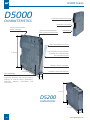
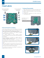
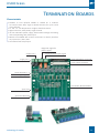
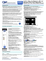
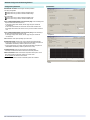
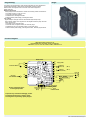
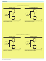
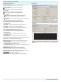
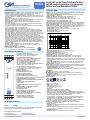
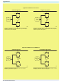
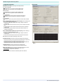
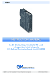
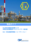
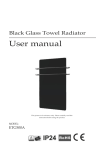
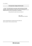
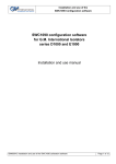
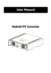
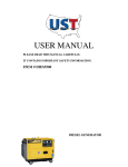
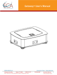
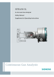
D5000 S D5000 ENHANCED INTRINSICALLY SAFE ISOLATORS SUITABLE FOR SIL 2 AND SIL 3 APPLICATIONS technology for safety 17 D5000 S D5000 Termina on Board connector CHARACTERISTICS Power Bus connector Guides for Termina on board moun ng Safe Area Terminal blocks with engraved iden fica on DIN-Rail lock Lexan detachable front cover LEDs for power, status and fault indica on are visible through the transparent cover 120 mm Modules are SIL 3 cer fied Hazardous Area Side indicator 123 mm Laser engraving on en re enclosure and terminal blocks to provide accurate, safe and permanent marking of Intrinsic Safety parameters, schema c diagrams, connec ons and instruc ons. 12.5 mm 120 mm D5200 DIMENSIONS 123 mm 22.5 mm 18 www.gmintsrl.com D5000 S High Performance • High signal transfer accuracy and repeatability. • Advanced circuitry provides very low heat dissipa on, ensuring modules run cool despite their high density and func onality. • SMD manufacturing for a long, reliable life. • Complete absence of electroly c capacitors ensures minimum 20 years life me. Wide FuncƟonality • Wide range of digital and analog I/O. • SIL 3 Safety Relay contacts rated for 4 A or 10 A for direct switching of high loads. • Three port galvanic isola on to eliminate noise, ground loop problems and to provide Intrinsic Safety without a high integrity safety earth connec on. • Line fault alarm detects open or short circuit of field cables. • Op onal power bus DIN-Rail connector. • Standard Termina on Board with custom connectors for integra on into customized Boards. • EMC Compa bility to EN61000-6-2, EN61000-6-4, EN61326-1, EN61326-3-1 for safety system. General Features • More than 25 modules suitable for SIL 3 applica ons according to IEC 61508, IEC 61511. • Independent power supply circuits for each channel on most modules. • Dual channel units are equivalent to two single units because of the absence of common circuitry on most modules. • Single channel versions available when required, to provide single loop integrity . • Configura on components are easily accessed by removing the side cover or via connector front panel. • DIP switch configurability for easy field setup. • LED indica on for power, signal status and line fault condi ons. • Modules accept DC power supply over a wide range for 24 Vdc (18-30 Vdc) applica ons. • Wide opera ng temp. range: -40 to +60/+70 °C. • Installa on in Zone 2 / Division 2. • Cer fied for Offshore and Marine applica ons. High Packing Density • High packing density. • 35 mm (Top Hat) DIN-Rail. • Ultra slim 2 channels 12 mm wide DIN-Rail and Termina on Board moun ng modules. • Power and fault on bus connectors. • 6 mm per channel means 50% space reduc on. • 3 mm per channel on DI module D5231E technology for safety 19 D5000 S F Blue Terminal Blocks for Hazardous Area connec ons Enclosure CharacterisƟcs Grey Terminal Blocks for Safe Area connec ons • High channel density result from innova ve circuit design using advanced surface mount components. • Plug-in screw terminal blocks to secure termina on up to 2.5 mm2. • Configura on components are easily accessed by removing side cover. Detachable Cover for direct access to configura on components Enhanced Power Bus mounƟng Power Supply Voltage, 24 Vdc, can be applied to the module by connec ng the voltage directly to the plug-in Terminal Block of each module, or via the Power Bus System. The system consists of standard DIN-Rail modules mounted on DIN-Rail Bus connectors. The maximum allowed powering capacity per trunk is 8 A. It is always possible to remove modules, without disconnec ng the bus connector which remains a ached to the DIN-Rail. Communica on bus is provided, on suitable models, to transmit via Modbus to DCS PLC logic solver to read input variables, diagnos c condi ons, etc. Cumula ve Fault Alarm indica on is provided on the Bus connec on. This signal can be fed to a common unit (D5202S) which provides SPST Relay contact for common faults. Both supply voltages are independently monitored and over or under condi on are signaled via SPST Relay contact for power good (supply within opera ng range). BUS PLUG IN CONNECTOR BUS CONNECTOR TERMINAL The D5202S is also capable of opera ng as a redundant 4 A supply module for the system. DIN RAIL STOPPER 20 www.gmintsrl.com D5000 S T B CharacterisƟcs • Suitable to host 8/16/32 D5000 or D5200 SIL 3 modules 12.5mm/22.5mm wide, single or double channel, for up to a total of 32 channels. • AI - AO - DI - DO Temperature: single or double channels. • Signal converter, Safety Relay: single channel. • 24 Vdc redundant power supply, with window voltage monitoring and corresponding relay fault output. • Boards are available with custom connectors to directly interface any system PLC / DCS / ESD. • Cumula ve fault relay output. Diagnos c signal for power supply Supply line 2 Supply line 1 Common fault output signal HART Mul plexer connector 16 ch output connector Power ON LEDs 1 - 2 Fault signaling LEDs Termina on Board Modules Spare fuse Space for Board tag technology for safety 21 D5000 S C SWC5090 SoŌware The SWC5090 so ware is designed to provide a PC user interface to configure suitable D5000, D5200 modules, via PPC5092 adapter. It easily allows the user to: • Read and write configura on parameters to the unit; • Store and restore data to and from local hard drive for backup or archive; • Load factory default configura ons; • Monitor real me Input values for debug or test; • Print a report sheet containing configura on parameters and addi onal informa on. The SWC5090 is freely distributed at our website: www.gmintsrl.com PPC5092 USB Adapter PPC5092 interface allows the configura on of D5000, D5200 modules via SWC5090 so ware. Modules are supplied via USB for programming and therefore do not need any external power supply. Power Supply is requested for input monitoring or analog output check. PPC5092 comes with mini-USB dedicated cable and CD-Rom containing SWC5090 so ware. 22 www.gmintsrl.com D5293 Characteristics: Technical Data: General Description: The D5293S is a relay module suitable for the switching of safety related circuits, up to SIL 3 level according to IEC 61508:2010 Ed.2, for high risk industries. It provides isolation between input and output contacts. A wide compatibility towards different DCS/PLC is guaranteed: driving line pulse testing, executed by DCS/PLC, is permitted by a dedicated internal circuit, to prevent relay and LED flickering. Internal relay coil short circuit is detected from module. D5293S provides 1+1 SPST contact for normally energized load. SIL 3 Safety Function for NE load (de-energized in fail safe state) is available at Terminal Blocks 13-14; When the driving signal is high (24 Vdc), the relay is energized (normal state), SIL 3 contacts at terminals 13-15 and 14-16 are closed, the load is energized. The safety function is met when the driving signal is low (0 Vdc), the relay is de-energized (fail safe state), SIL 3 contacts at terminals 13-15 and 14-16 are opened, the load is de-energized. Load is isolated from supply on both polarities: +/AC, -/AC. Load and Line Diagnostic: Line and load short/open circuit detection is provided. Load RMS voltage (before and after its energization) and current are measured from module. Load voltage and current can automatically be acquired from field. User configurable limits set the minimum and maximum values of supply voltage (DC or AC) and load current. The fault in the field is directly mirrored to the PLC DO: few systems may exceptionally require an external resistor at terminals 7 and 8. All diagnostic conditions, that detect a fault on line and load, open the fault relay contacts and are also available from a RS485 Modbus output to identify specific fault. Diagnostic functions with fault relay NO contacts and RS485 Modbus output are SIL 2 according to IEC 61511. Mounting on standard DIN-Rail, with or without Power Bus, or on customized Termination Boards, in Safe Area / Non Hazardous Location or in Zone 2 / Class I, Division 2 or Class I, Zone 2. Functional Safety Management Certification: G.M. International is certified by TUV to conform to IEC61508:2010 part 1 clauses 5-6 for safety related systems up to and included SIL3. FSM SIL 3 Front Panel and Features: 9 5 1 10 6 2 11 7 3 12 8 4 CONFIG PWR FLT STS SIL 3 D5293 13 14 15 16 21 22 23 24 SIL 3 according to IEC 61508:2010 Ed. 2 for Tproof = 13 / 20 yrs (10 / 20 % of total SIF) for NE Load SIL 2 according to IEC 61508:2010 Ed. 2 for Tproof = 20 yrs (10 % of total SIF) for NE Load. PFDavg (1 year) 7.55 E-06, SFF 99.02 % for NE Load. SIL 2 according to IEC 61511 for Tproof = 2 / 4 yrs (10 / 20 % of total SIF) for diagnostic with fault relay NO contact, with PFDavg (1 year) 4.26 E-04, SFF 69.07 % SIL 2 according to IEC 61511 for Tproof = 4 / 8 yrs (10 / 20 % of total SIF) for diagnostic with RS485 Modbus out, with PFDavg(1 yr) 2.25E-04, SFF 73.84% Systematic capability SIL 3. Installation in Zone 2 / Division 2. Compatible with DCS/PLC pulse testing. Internal relay coil short circuit detection. Line and Load short/open circuit detection. The fault in the field is directly mirrored to the PLC DO. RMS measurement of voltage (before and after load energization) and load current. Automatic acquisition of voltage and current values. 4 A SIL 3 contacts for NE load. 6 A inrush current at 24 Vdc / 250 Vac. Input/Output/Supply isolation. EMC Compatibility to EN61000-6-2, EN61000-6-4, EN61326-1, EN61326-3-1 for safety system. ATEX, IECEx, FM, FMC, INMETRO, GOST, TÜV Certifications. TUV Functional Safety Certification. Type Approval Certificate DNV and KR for maritime applications. Simplified installation using standard DIN-Rail and plug-in terminal blocks, with or without Power Bus, or customized Termination Boards. Ordering Information: Model: D5293S Operating parameters are programmable from PC by the GM Pocket Portable Adapter PPC5092 via USB serial line and SWC5090 Configurator software. Power Bus and DIN-Rail accessories: Connector JDFT050 Cover and fix MCHP196 Terminal block male MOR017 Terminal block female MOR022 G.M. International DTS0339-9 Page 1/3 4 A SIL 3 Relay Out Module for NE Load with open/short circuit diagnostic DIN-Rail and Term. Board, Model D5293S Supply: 24 Vdc nom (21.6 to 27.6 Vdc) reverse polarity protected, ripple within voltage limits ≤ 5 Vpp, 2 A time lag fuse internally protected. Current consumption @ 24 V: 40 mA typical, with channel energized and no fault. Power dissipation: 1 W typical. Isolation (Test Voltage): Output/Input 2.5 KV; Output/Supply 2.5 KV; Output/Fault Outputs 2.5 KV; Output/RS485 Modbus 2.5 KV; Input/Supply 500 V; Input/Fault Output 1 500 V; Input/Fault Output 2 2.5 KV; Input/RS485 Modbus 500 V; Supply/Fault Output 1 500 V; Supply/Fault Output 2 2.5 KV; Supply/RS485 Modbus 500 V. Input: 24 Vdc nom (21.6 to 27.6 Vdc) reverse polarity protected, ripple within voltage limits ≤ 5 Vpp. Current consumption @ 24 V: 50 mA (with mirror and no fault), 25 mA (otherwise). Power dissipation @ 24 V: 1.2 W (with mirror and no fault), 0.6 W (otherwise). Output: voltage free 1 + 1 SPST relay contact at terminals 13-15 and 14-16, opens when relay de-energized (fail safe state), close in energized condition. Contact material: Ag Alloy (Cd free), gold plated. Contact rating: 4 A 250 Vac 1000 VA, 4 A 250 Vdc 120 W (resistive load). Min. switching current 1 mA. Contact inrush current: 6 A at 24 Vdc, 250 Vac. DC Load breaking capacity: V (V ) 300 250 200 R e s is tiv e Load 100 50 40 30 20 I (A ) 10 0 .1 0 .2 0 .3 0 .4 0 .5 1 2 3 4 Mechanical / Electrical life: 5 * 106 / 3 * 104 operation, typical. Operate / Release time: 8 / 4 ms typical. Bounce time NO / NC contact: 3 / 8 ms, typical. Frequency response: 10 Hz maximum. Fault detection: load and line short/open circuit monitoring Short output detection: programmable load current (5 mA to 4 A typical). Open output detection: programmable load current (5 mA to 4 A typical). Fault signaling: voltage free NE 1 + 1 SPST relay contacts (closed in normal status), output de-energized (contacts opened) in fault condition. Fault contact can be reversed via software. Fault 1 output rating: 500 mA 30 Vac 15 VA, 500 mA 50 Vdc 25 W (resistive load). Fault 2 output rating: 3 A 250 Vac 750 VA, 3 A 125 Vdc 120 W (resistive load). Response time: 1 sec typical. Modbus Output: measure data, load and line diagnostic monitoring. Modbus RTU protocol up to 115.2 Kbit/s with RS-485 connection on terminal blocks and Power Bus connector. Terminating impedance: 100 Ω software selectable. Transmission speed: 4.8, 9.6, 19.2, 38.4, 57.6, 115.2 Kbit/s. Transmission cable length: ≤ 1200 m up to 93.75 Kbit/s, ≤ 1000 m up to 115.2 Kbit/s. Compatibility: CE mark compliant, conforms to Directives: 94/9/EC Atex, 2004/108/CE EMC, 2006/95/EC LVD, 2011/65/EU RoHS. Environmental conditions: Operating: temperature limits – 40 to + 60 °C, relative humidity 95 %, up to 55 °C. Storage: temperature limits - 45 to + 80 °C. Safety Description: ATEX: II 3G Ex nA nC IIC T4 Gc IECEx / INMETRO: Ex nA nC IIC T4 Gc FM: NI / I / 2 / ABCD /T4, I / 2 / AEx nA nC / IIC /T4 FMC: NI / I / 2 / ABCD /T4, I / 2 / Ex nA nC / IIC /T4 TRCU: 2ExnAnCIICT4 X. non-sparking electrical equipment. -40 °C ≤ Ta ≤ 70 °C. Approvals: BVS 10 ATEX E 114 conforms to EN60079-0, EN60079-15. IECEx BVS 10.0072 X conforms to IEC60079-0, IEC60079-15. INMETRO DNV 13.0109 X conforms to ABNT NBR IEC60079-0, ABNT NBR IEC60079-15. FM 3046304 and FMC 3046304C conforms to Class 3600, 3611, 3810, ANSI/ISA-60079-0, ANSI/ISA-60079-15, C22.2 No.142, C22.2 No.213, C22.2 No. 60079-0, C22.2 No. 60079-15. Conforms to GOST 30852.0-2002, 30852.14-2002. TÜV Certificate No. C-IS-236198-04, SIL 2 / SIL 3 conforms to IEC61508:2010 Ed.2. TÜV Certificate No. C-IS-236198-09, SIL 3 Functional Safety Certificate conforms to IEC61508:2010 Ed.2, for Management of Functional Safety. (Pending) SIL 2 conforms to IEC 61511 for Line and Load Diagnostic Functionalities. DNV Type Approval Certificate No.A-13625 and KR No.MIL20769-EL002 Certificates for maritime applications . Patent No. 0001406495 , released on 28/02/3014, valid for 20 years. Mounting: T35 DIN-Rail according to EN50022, with or without Power Bus or on customized Termination Board. Weight: about 230 g. Connection: by polarized plug-in disconnect screw terminal blocks to accommodate terminations up to 2.5 mm2. Location: installation in Safe Area/Non Hazardous Locations or Zone 2, Group IIC T4 or Class I, Division 2, Group A,B,C,D, T4 or Class I, Zone 2, Group IIC, T4. Protection class: IP 20. Dimensions: Width 22.5 mm, Depth 123 mm, Height 120 mm. www.gmintsrl.com Programming: Image: The module is fully programmable to set the operation parameters from PC by the GM Pocket Portable Adapter PPC5092 via USB serial line and SWC5090 Configurator software. Measured values and diagnostic alarms can be read on both serial configuration or Modbus output line. Measuring and Set limits: working voltage and load characteristics to indicate normal working condition. Parameters are: - Line Voltage value from 10 to 250 Vdc or Vac. - Load Current for energized condition. Type of Faults: programmability of which type of faults can deactivate the diagnostic relay output. Each of the fault condition can be programmed to de-energize the fault relay output. Faults are: - Relay coil short circuit. - Line Voltage value out of boundary range. - Load Current value, in energized condition, out of boundary range. Function Diagram: SAFE AREA, ZONE 2 GROUP IIC T4, NON HAZARDOUS LOCATIONS, CLASS I, DIVISION 2, GROUPS A, B, C, D T-Code T4, CLASS I, ZONE 2, GROUP IIC T4 MODEL D5293S Load and Line Diagnostic + 15 - 16 Load Power DC/AC Supply 24 Vdc 11 12 Fault Out 2 (250 V, 3 A) (SIL 2) 3 4 Fault Out 1 (30 V, 500 mA) (SIL 2) 1 2 All relay contacts are shown in de-energized position Modbus RS485 + 13 - 14 (SIL 3) Out NE Load 9+ 10 - To prevent relay contacts from damaging, connect an external protection (fuse or similar), chosen according to the relay breaking capacity diagram. B+ A- F - + Modbus RS485 Power and for diagnostic Fault Bus (SIL 2) + 5 A6 B+ 7 8 MODBUS IN/OUT RS485 (SIL 2) In Optional external resistor Termination board connector (SIL 2) for Modbus RS485 Application for D5293S - SIL 3 Load Normally Energized Condition (NE) Normal state operation De-energized to trip operation + / AC + / AC 15 15 13 13 PLC Output ON 24 Vdc PLC Output OFF 0 Vdc Load Load 14 14 16 16 - / AC - / AC Contacts 13-15 and 14-16: in normal operation the relay is energized, contacts are closed, load is energized. Contacts 13-15 and 14-16: the SIL 3 Safety Function is met when the relay is de-energized, contacts are open, load is de-energized. G.M. International DTS0339-9 Page 2/3 SWC5090 Configuration & Monitoring Software Configuration parameters: Screenshots: USER MANUAL SETTINGS: Allowed ranges of the field parameters. Load Supply Voltage RMS Voltage Upper Limit (V): Maximum allowed load RMS voltage Voltage Lower Limit (V): Minimum allowed load RMS voltage Load Current RMS Current Upper Limit (A): Maximum allowed load RMS current Current Lower Limit (A): Minimum allowed load RMS current FAULT CONDITIONS MONITORING (Command Status [ON]): Faults contributing to the output cumulative fault when the driver is on. Load Supply Voltage: When checked, the load supply voltage can activate the cumulative fault. Load Current: When checked, the load current can activate the cumulative fault. Coil Integrity: When checked, the short circuit of any coil can activate the cumulative fault. FAULT CONDITIONS MONITORING (Command Status [OFF]): Faults contributing to the output cumulative fault when the driver is off. Load Supply Voltage: When checked, the load supply voltage can activate the cumulative fault. Configuration TAG: Identification of the specific operating loop of the module. ACQUIRE FUNCTIONS: Acquisition and saving of the diagnostics field parameters. Acquire OFF parameters: The currently measured OFF parameters are copied to the USER MANUAL SETTINGS (available only when the driver is OFF). Acquire ON parameters: The currently measured ON parameters are copied to the USER MANUAL SETTINGS (available only when the driver is ON). CONTINUOUS SCAN: Continuous measurement of the field parameters. Start/Stop: Activates/de-activates the measurement of the field parameters. INVERT FAULT RELAY: When not checked, the output fault contacts open in case of fault. When checked, the output fault contacts close in case of fault. For SIL application, this field must not be checked. Note: For advanced options and details on SWC5090, please refer to ISM0154. Monitor G.M. International DTS0339-9 Page 3/3 D5294 Characteristics: General Description: The D5294S is a relay module suitable for the switching of safety related circuits, up to SIL 3 level according to IEC 61508:2010 Ed. 2 for high risk industries. It provides isolation between input and output contacts. A wide compatibility towards different DCS/PLC is guaranteed: driving line pulse testing, executed by DCS/PLC, is permitted by a dedicated internal circuit, to prevent relay and LED flickering. Internal relay coil short circuit is detected from module. D5294S has 2+2 SPST relay contacts connected in parallel and then in series to avoid spurious trip and to increase availability (see function diagram). High availability SIL 3 Safety Function for NE load or F&G / ND load is available at Terminal Blocks 13-14. When the driving signal is low (0 Vdc), the relay is de-energized, contacts at terminals 13-15 and 14-16 are open and load is de-energized. When the driving signal is high (24 Vdc), the relay is energized, contacts at terminals 13-15 and 14-16 are closed, the load is energized. Load is isolated from supply on both polarities: +/AC, -/AC. Load and Line Diagnostic: Line and load short/open circuit detection is provided, with solenoid resistance measurement, even in presence of series connected diodes. A patented proprietary resistance measuring technique performs the load short and open circuit diagnosis in de-energized load status, for DC or AC supply systems. Load RMS voltage (before and after its energization) and current are measured from module. Load voltage, current and resistance can automatically be acquired from field. User configurable limits set the minimum and maximum values of load resistance, supply voltage (DC or AC) and load current. Earth leakage detection on both AC phases is available in de-energized load condition. The fault in the field is directly mirrored to the PLC DO: few systems may exceptionally require an external resistor at terminals 7 and 8. All diagnostic conditions, that detect a fault on line and load, open the fault relay contacts and are also available from a RS485 Modbus output to identify specific fault. Diagnostic functions with fault relay NO contacts and RS485 Modbus output are SIL 2 according to IEC 61511. Mounting on standard DIN-Rail, with or without Power Bus, or on customized Termination Boards, in Safe Area / Non Hazardous Location or in Zone 2 / Class I, Division 2 or Class I, Zone 2. Functional Safety Management Certification: G.M. International is certified by TUV to conform to IEC61508:2010 FSM part 1 clauses 5-6 for safety related systems up to and included SIL3. SIL 3 Front Panel and Features: SIL 3 according to IEC 61508:2010 Ed. 2 9 5 1 10 6 2 11 7 3 12 8 4 CONFIG PWR FLT STS SIL 3 D5294 13 14 15 16 21 22 23 24 for Tproof = 13 / 20 yrs (10 / 20 % of total SIF) for NE Load, with PFDavg (1 year) 7.55 E-06, SFF 99.29 % SIL 3 according to IEC 61508:2010 Ed. 2 for Tproof = 6 / 13 yrs (10 / 20 % of total SIF) for F&G/ND Load, with PFDavg (1 year) 1.49 E-05, SFF 97.52 % SIL 2 according to IEC 61508:2010 Ed. 2 for Tproof = 20 yrs (10 % or more of total SIF) - for NE load and F&G/ND load. SIL 2 according to IEC 61511 for Tproof = 1 / 3 yrs (10 / 20 % of total SIF) for diagnostic with fault relay NO contact, with PFDavg (1 year) 5.86 E-04, SFF 70.54 % SIL 2 according to IEC 61511 for Tproof = 2 / 5 yrs (10 / 20 % of total SIF) for diagnostic with RS485 Modbus out with PFDavg (1 year) 3.85 E-04, SFF 73.82 % Systematic capability SIL 3 Installation in Zone 2 / Division 2. Compatible with DCS/PLC pulse testing. Internal relay coil short circuit detection. Line and Load short/open circuit detection. The fault in the field is directly mirrored to the PLC DO. Solenoid resistance measurement even in presence of serial connected diodes (patented resistance measuring technique). RMS measurement of voltage (before and after load energization) and load current. Automatic acquisition of voltage, current and load resistance values. Earth leakage detection on both ac phases in de-energized load condition. 4 A high availability SIL 3 contacts for NE or F&G/ND load. 6 A inrush current at 24 Vdc / 250 Vac. Input/Output/Supply isolation. EMC Compatibility to EN61000-6-2, EN61000-6-4, EN61326-1, EN61326-3-1 for safety system. ATEX, IECEx, FM, FMC, INMETRO, GOST, TÜV Certifications. TÜV Functional Safety Certification. Type Approval Certificate DNV and KR for maritime applications. Simplified installation using standard DIN-Rail and plug-in terminal blocks, with or without Power Bus, or customized Termination Boards. Ordering Information: Model: D5294S Operating parameters are programmable from PC by the GM Pocket Portable Adapter PPC5092 via USB serial line and SWC5090 Configurator software. Power Bus and DIN-Rail accessories: Connector JDFT050 Cover and fix MCHP196 Terminal block male MOR017 Terminal block female MOR022 G.M. International DTS0340-9 Page 1/4 4 A SIL 3 NO contact Relay Out Module for NE or F&G/ND Load with open/short circuit diagnostic DIN-Rail and Term. Board Model D5294S Technical Data: Supply: 24 Vdc nom (21.6 to 27.6 Vdc) reverse polarity protected, ripple within voltage limits ≤ 5 Vpp, 2 A time lag fuse internally protected. Current consumption @ 24 V: 45 mA typical, with channel de-energized and no fault. Power dissipation: 1.1 W typical. Isolation (Test Voltage): Output/Input 2.5 KV; Output/Supply 2.5 KV; Output/Fault Outputs 2.5 KV; Output/RS485 Modbus 2.5 KV; Input/Supply 500 V; Input/Fault Output 1 500 V; Input/Fault Output 2 2.5 KV; Input/RS485 Modbus 500 V; Supply/Fault Output 1 500 V; Supply/Fault Output 2 2.5 KV; Supply/RS485 Modbus 500 V. Input: 24 Vdc nom (21.6 to 27.6 Vdc) reverse polarity protected, ripple within voltage limits ≤ 5 Vpp. Current consumption @ 24 V: 60 mA (with mirror and no fault), 35 mA (otherwise). Power dissipation @ 24 V: 1.45 W (with mirror and no fault), 0.85 W (otherwise). Output: voltage free 2+2 SPST relay contact (2 paralleled contacts in series) at terminals 13-15 and 14-16, close when relay energized, open in de-energized condition. Contact material: Ag Alloy (Cd free), gold plated. Contact rating: 4 A 250 Vac 1000 VA, 4 A 250 Vdc 120 W (resistive load). Min.switching current 1 mA. Contact inrush current: 6 A at 24 Vdc, 250 Vac. DC Load breaking capacity: V (V ) 300 250 200 R e s is tiv e Load 100 50 40 30 20 I (A ) 10 0 .1 0 .2 0 .3 0 .4 0 .5 1 2 3 4 Mechanical / Electrical life: 5 * 106 / 3 * 104 operation, typical. Operate / Release time: 8 / 4 ms typical. Bounce time NO / NC contact: 3 / 8 ms, typical. Frequency response: 10 Hz maximum. Fault detection: load and line short/open circuit monitoring Short output detection: programmable load resistance (5 Ω to 49 KΩ typical). Open output detection: programmable load resistance (5 Ω to 49 KΩ typical). Fault signalling: voltage free NE 1 + 1 SPST relay contacts (closed in normal status), output de-energized (contacts opened) in fault condition. Fault contact can be reversed via software. Fault 1 output rating: 500 mA 30 Vac 15 VA, 500 mA 50 Vdc 25 W (resistive load). Fault 2 output rating: 3 A 250 Vac 750 VA, 3 A 125 Vdc 120 W (resistive load). Response time: 1 sec typical. Modbus Output: measure data, load and line diagnostic monitoring. Modbus RTU protocol up to 115.2 Kbit/s with RS-485 connection on terminal blocks and Power Bus connector. Terminating impedance: 100 Ω software selectable, Transmission speed: 4.8, 9.6, 19.2, 38.4, 57.6, 115.2 Kbit/s. Transmission cable length: ≤ 1200 m up to 93.75 Kbit/s, ≤ 1000 m up to 115.2 Kbit/s. Compatibility: CE mark compliant, conforms to Directives: 94/9/EC Atex, 2004/108/CE EMC, 2006/95/EC LVD, 2011/65/EU RoHS. Environmental conditions: Operating: temperature limits – 40 to + 60 °C, relative humidity 95 %, up to 55 °C. Storage: temperature limits - 45 to + 80 °C. Safety Description: ATEX: II 3G Ex nA nC IIC T4 Gc. IECEx / INMETRO: Ex nA nC IIC T4 Gc FM: NI / I / 2 / ABCD / T4 FMC: NI-AIS / I / 2 / ABCD / T4 TRCU: 2ExnAnCIICT4 X. non-sparking electrical equipment. -40 °C ≤ Ta ≤ 70 °C. Approvals: BVS 10 ATEX E 114 conforms to EN60079-0, EN60079-15. IECEx BVS 10.0072 X conforms to IEC60079-0, IEC60079-15 INMETRO DNV 13.0109 X conforms to ABNT NBR IEC60079-0, ABNT NBR IEC60079-15. FM 3046304 and FMC 3046304C conforms to Class 3600, 3611, 3810, ANSI/ISA-60079-0, ANSI/ISA-60079-15, C22.2 No.142, C22.2 No.213, C22.2 No. 60079-0, C22.2 No. 60079-15. Conforms to GOST 30852.0-2002, 30852.14-2002 TUV Certificate No. C-IS-236198-04, SIL 2 / SIL 3 conforms to IEC61508:2010 Ed. 2. TÜV Certificate No. C-IS-236198-09, SIL 3 Functional Safety Certificate conforms to IEC61508:2010 Ed.2, for Management of Functional Safety. (Pending) SIL 2 conforms to IEC 61511 for Line and Load Diagnostic Functionalities. DNV Type Approval Certificate No.A-13625 and KR No.MIL20769-EL002 Certificates for maritime applications. Patent No. 0001406495 , released on 28/02/2014, valid for 20 years. Mounting: T35 DIN-Rail according to EN50022, with or without Power Bus or on customized Termination Board. Weight: about 235 g. Connection: by polarized plug-in disconnect screw terminal blocks to accommodate terminations up to 2.5 mm2. Location: installation in Safe Area/Non Hazardous Locations or Zone 2, Group IIC T4 or Class I, Division 2, Group A,B,C,D, T4 or Class I, Zone 2, Group IIC, T4. Protection class: IP 20. Dimensions: Width 22.5 mm, Depth 123 mm, Height 120 mm. www.gmintsrl.com Programming: Image: The module is fully programmable to set the operation parameters from PC by the GM Pocket Portable Adapter PPC5092 via USB serial line and SWC5090 Configurator software. Measured values and diagnostic alarms can be read on both serial configuration or Modbus output line. Measuring and Set limits: working voltage and load characteristics to indicate normal working condition. Parameters are: - Line Voltage value from 10 to 250 Vdc or Vac. - Load Current for energized condition. - Load Resistance for de-energized condition. - Isolation resistance (Earth Leakage) in de-energized condition. Type of Faults: programmability of which type of faults can deactivate the diagnostic relay output. Each of the fault condition can be programmed to de-energize the fault relay output. Faults are: - Relay coil short circuit. - Line Voltage value out of boundary range. - Load Current value, in energized condition, out of boundary range. - Load Resistance value, in de-energized condition, out of boundary range. - Isolation resistance (Earth Leakage), in de-energized condition, below the programmed limit. Function Diagram: SAFE AREA, ZONE 2 GROUP IIC T4, NON HAZARDOUS LOCATIONS, CLASS I, DIVISION 2, GROUPS A, B, C, D T-Code T4, CLASS I, ZONE 2, GROUP IIC T4 MODEL D5294S 21 Load Power DC/AC (SIL 3) Out NE or F&G/ND Load + 15 - 16 Load and Line Diagnostic Supply 24 Vdc 11 12 Fault Out 2 (250 V, 3 A) (SIL 2) 3 4 Fault Out 1 (30 V, 500 mA) (SIL 2) 1 2 + 13 - 14 Modbus RS485 All relay contacts are shown in de-energized position 9+ 10 - B+ A- F - + Modbus RS485 Power and for diagnostic Fault Bus (SIL 2) 5 A6 B+ 7 8 + MODBUS IN/OUT RS485 (SIL 2) In Optional external resistor Termination board connector (SIL 2) for Modbus RS485 To prevent relay contacts from damaging, connect an external protection (fuse or similar), chosen according to the relay breaking capacity diagram. G.M. International DTS0340-9 Page 2/4 Applications: Application for D5294S - SIL 3 for NE Load Normal state operation De-energized to trip operation + / AC + / AC 15 15 13 13 PLC Output ON 24 Vdc PLC Output OFF 0 Vdc Load Load 14 14 16 16 - / AC Contacts 13-15 and 14-16: in normal operation the relay is energized, contacts are closed, load is energized. - / AC Contacts 13-15 and 14-16: the SIL 3 Safety Function the relay is de-energized, contacts are open, load is de-energized. Application for D5294S - SIL 3 for F&G/ND Load Normal state operation Energized to trip operation + / AC + / AC 15 15 13 13 PLC Output OFF 0 Vdc PLC Output ON 24 Vdc Load 14 14 16 16 - / AC Contacts 13-15 and 14-16: in normal operation the relay is de-energized, contacts are open, load is de-energized. G.M. International DTS0340-9 Page 3/4 Load - / AC Contacts 13-15 and 14-16: the SIL 3 Safety Function is met when the relay is energized, contacts are closed, load is energized. SWC5090 Configuration & Monitoring Software Configuration parameters: Screenshots: USER MANUAL SETTINGS: Allowed ranges of the field parameters. Load Supply Voltage RMS Voltage Upper Limit (V): Maximum allowed load RMS voltage Voltage Lower Limit (V): Minimum allowed load RMS voltage Load Current RMS Current Upper Limit (A): Maximum allowed load RMS current Current Lower Limit (A): Minimum allowed load RMS current Load OFF Resistance Resistance Upper Limit (Ω): Maximum allowed load OFF resistance Resistance Lower Limit (Ω): Minimum allowed load OFF resistance Isolation Resistance Resistance Lower Limit (kΩ): Minimum allowed load-to-earth isolation resistance FAULT CONDITIONS MONITORING (Command Status [ON]): Faults contributing to the output cumulative fault when the driver is on. Load Supply Voltage: When checked, the load supply voltage can activate the cumulative fault. Load Current: When checked, the load current can activate the cumulative fault. Coil Integrity: When checked, the short circuit of any coil can activate the cumulative fault. Configuration FAULT CONDITIONS MONITORING (Command Status [OFF]): Faults contributing to the output cumulative fault when the driver is off. Load Supply Voltage: When checked, the load supply voltage can activate the cumulative fault. Load OFF Resistance: When checked, the load OFF resistance can activate the cumulative fault. Isolation Resistance: When checked, the load-to-earth isolation resistance can activate the cumulative fault. TAG: Identification of the specific operating loop of the module. ACQUIRE FUNCTIONS: Acquisition and saving of the diagnostics field parameters. Acquire OFF parameters: The currently measured OFF parameters are copied to the USER MANUAL SETTINGS (available only when the driver is OFF). Acquire ON parameters: The currently measured ON parameters are copied to the USER MANUAL SETTINGS (available only when the driver is ON). Monitor CONTINUOUS SCAN: Continuous measurement of the field parameters. Start/Stop: Activates/de-activates the measurement of the field parameters. INVERT FAULT RELAY: When not checked, the output fault contacts open in case of fault. When checked, the output fault contacts close in case of fault. For SIL application, this field must not be checked. Note: For advanced options and details on SWC5090, please refer to ISM0154. G.M. International DTS0340-9 Page 4/4 D5295 Characteristics: General Description: The D5295S is a relay module suitable for the switching of safety related circuits, up to SIL 3 level according to IEC 61508:2010 Ed. 2 for high risk industries. It provides isolation between input and output contacts. A wide compatibility towards different DCS/PLC is guaranteed: driving line pulse testing, executed by DCS/PLC, is permitted by a dedicated internal circuit, to prevent relay and LED flickering. Internal relay coil short circuit is detected from module. D5295S has 2+2 SPST relay contacts connected in parallel and then in series to avoid spurious trip and to increase availability (see function diagram). High availability SIL 3 Safety Function for NE load or F&G / ND load is available at Terminal Blocks 13-14. When the driving signal is high (24 Vdc), the relay is energized, contacts at terminals 13-15 and 14-16 are open and load is de-energized. When the driving signal is low (0 Vdc), the relay is de-energized, contacts at terminals 13-15 and 14-16 are closed, the load is energized. Load is isolated from supply on both polarities: +/AC, -/AC. Load and Line Diagnostic: Line and load short/open circuit detection is provided, with solenoid resistance measurement, even in presence of series connected diodes. A patented proprietary resistance measuring technique performs the load short and open circuit diagnosis in de-energized load status, for DC or AC supply systems. Load RMS voltage (before and after its energization) and current are measured from module. Load voltage, current and resistance can automatically be acquired from field. User configurable limits set the minimum and maximum values of load resistance, supply voltage (DC or AC) and load current. Earth leakage detection on both AC phases is available in de-energized load condition. The fault in the field is directly mirrored to the PLC DO: few systems may exceptionally require an external resistor at terminals 7 and 8. All diagnostic conditions, that detect a fault on line and load, open the fault relay contacts and are also available from a RS485 Modbus output to identify specific fault. Diagnostic functions with fault relay NO contacts and RS485 Modbus output are SIL 2 according to IEC 61511. Mounting on standard DIN-Rail, with or without Power Bus, or on customized Termination Boards, in Safe Area / Non Hazardous Location or in Zone 2 / Class I, Division 2 or Class I, Zone 2. Functional Safety Management Certification: G.M. International is certified by TUV to conform to IEC61508:2010 FSM part 1 clauses 5-6 for safety related systems up to and included SIL3. SIL 3 Front Panel and Features: SIL 3 according to IEC 61508:2010 Ed. 2 9 5 1 10 6 2 11 7 3 12 8 4 CONFIG PWR FLT STS SIL 3 D5295 13 14 15 16 21 22 23 24 for Tproof = 7 / 14 yrs (10 / 20 % of total SIF) for NE Load, with PFDavg (1 year) 1.39 E-05, SFF 97.71 % SIL 3 according to IEC 61508:2010 Ed. 2 for Tproof = 11 / 20 yrs (10 / 20 % of total SIF) for F&G/ND Load, with PFDavg (1 year) 8.64 E-06, SFF 99.18 % SIL 2 according to IEC 61508:2010 Ed. 2 for Tproof = 20 yrs (10 % of total SIF) for NE load and F&G/ND Load. SIL 2 according to IEC 61511 for Tproof = 1 / 3 yrs (10 / 20 % of total SIF) for diagnostic with fault relay NO contact, with PFDavg (1 year) 5.86 E-04, SFF 70.54 % SIL 2 according to IEC 61511 for Tproof = 2 / 5 yrs (10 / 20 % of total SIF) for diagnostic with RS485 Modbus out, with PFDavg (1 year) 3.85 E-04, SFF 73.82 % Systematic capability SIL 3 Installation in Zone 2 / Division 2. Compatible with DCS/PLC pulse testing. Internal relay coil short circuit detection. Line and Load short/open circuit detection. The fault in the field is directly mirrored to the PLC DO. Solenoid resistance measurement even in presence of serial connected diodes (patented resistance measuring technique). RMS measurement of voltage (before and after load energization) and load current. Automatic acquisition of voltage, current and load resistance values. Earth leakage detection on both ac phases in de-energized load condition. 4 A high availability SIL 3 contacts for NE or F&G/ND load. 6 A inrush current at 24 Vdc / 250 Vac. Input/Output/Supply isolation. EMC Compatibility to EN61000-6-2, EN61000-6-4, EN61326-1, EN61326-3-1 for safety system. ATEX, IECEx, FM, FMC, INMETRO, GOST, TÜV Certifications TÜV Functional Safety Certification. Simplified installation using standard DIN-Rail and plug-in terminal blocks, with or without Power Bus, or customized Termination Boards. Ordering Information: Model: D5295S Operating parameters are programmable from PC by the GM Pocket Portable Adapter PPC5092 via USB serial line and SWC5090 Configurator software. 4 A SIL 3 NC contact Relay Out Module for NE or F&G/ND Load with open/short circuit diagnostic DIN-Rail and Term. Board Model D5295S Technical Data: Supply: 24 Vdc nom (21.6 to 27.6 Vdc) reverse polarity protected, ripple within voltage limits ≤ 5 Vpp, 2 A time lag fuse internally protected. Current consumption @ 24 V: 45 mA typical, with channel energized and no fault. Power dissipation: 1.1 W typical. Isolation (Test Voltage): Output/Input 2.5 KV; Output/Supply 2.5 KV; Output/Fault Outputs 2.5 KV; Output/RS485 Modbus 2.5 KV; Input/Supply 500 V; Input/Fault Output 1 500 V; Input/Fault Output 2 2.5 KV; Input/RS485 Modbus 500 V; Supply/Fault Output 1 500 V; Supply/Fault Output 2 2.5 KV; Supply/RS485 Modbus 500 V. Input: 24 Vdc nom (21.6 to 27.6 Vdc) reverse polarity protected, ripple within voltage limits ≤ 5 Vpp. Current consumption @ 24 V: 60 mA (with mirror and no fault), 35 mA (otherwise). Power dissipation @ 24 V: 1.45 W (with mirror and no fault), 0.85 W (otherwise). Output: voltage free 2+2 SPST relay contact (2 paralleled contacts in series) at terminals 13-15 and 14-16, open when relay energized, close in de-energized condition. Contact material: Ag Alloy (Cd free), gold plated. Contact rating: 4 A 250 Vac 1000 VA, 4 A 250 Vdc 120 W (resistive load). Min.switching current 1 mA. Contact inrush current: 6 A at 24 Vdc, 250 Vac. DC Load breaking capacity: V (V ) 300 250 200 R e s is tiv e Load 100 50 40 30 20 I (A ) 10 0 .1 0 .2 0 .3 0 .4 0 .5 1 2 3 4 Mechanical / Electrical life: 5 * 106 / 3 * 104 operation, typical. Operate / Release time: 8 / 4 ms typical. Bounce time NO / NC contact: 3 / 8 ms, typical. Frequency response: 10 Hz maximum. Fault detection: load and line short/open circuit monitoring Short output detection: programmable load resistance (5 Ω to 49 KΩ typical). Open output detection: programmable load resistance (5 Ω to 49 KΩ typical). Fault signalling: voltage free NE 1 + 1 SPST relay contacts (closed in normal status), output de-energized (contacts opened) in fault condition. Fault contact can be reversed via software. Fault 1 output rating: 500 mA 30 Vac 15 VA, 500 mA 50 Vdc 25 W (resistive load). Fault 2 output rating: 3 A 250 Vac 750 VA, 3 A 125 Vdc 120 W (resistive load). Response time: 1 sec typical. Modbus Output: measure data, load and line diagnostic monitoring. Modbus RTU protocol up to 115.2 Kbit/s with RS-485 connection on terminal blocks and Power Bus connector. Terminating impedance: 100 Ω software selectable, Transmission speed: 4.8, 9.6, 19.2, 38.4, 57.6, 115.2 Kbit/s. Transmission cable length: ≤ 1200 m up to 93.75 Kbit/s, ≤ 1000 m up to 115.2 Kbit/s. Compatibility: CE mark compliant, conforms to Directives: 94/9/EC Atex, 2004/108/CE EMC, 2006/95/EC LVD, 2011/65/EU RoHS. Environmental conditions: Operating: temperature limits – 40 to + 60 °C, relative humidity 95 %, up to 55 °C. Storage: temperature limits - 45 to + 80 °C. Safety Description: ATEX: II 3G Ex nA nC IIC T4 Gc. IECEx / INMETRO: Ex nA nC IIC T4 Gc FM: NI / I / 2 / ABCD / T4 FMC: NI-AIS / I / 2 / ABCD / T4 TRCU: 2ExnAnCIICT4 X. non-sparking electrical equipment. -40 °C ≤ Ta ≤ 70 °C. Approvals: ATEX conforms to EN60079-0, EN60079-15 (pending). IECEx conforms to IEC60079-0, IEC60079-15 (pending) INMETRO conforms to ABNT NBR IEC60079-0, ABNT NBR IEC60079-15 (pending). FM and FMC conforms to Class 3600, 3611, 3810, ANSI/ISA-60079-0, ANSI/ISA-60079-15, C22.2 No.142, C22.2 No.213, C22.2 No. 60079-0, C22.2 No. 60079-15 (pending). Conforms to GOST 30852.0-2002, 30852.14-2002 (pending) TUV Certificate No. C-IS-236198-04, SIL 2 / SIL 3 conforms to IEC61508:2010 Ed. 2. TÜV Certificate No. C-IS-236198-09, SIL 3 Functional Safety Certificate conforms to IEC61508:2010 Ed.2, for Management of Functional Safety. (Pending) SIL 2 conforms to IEC 61511 for Line and Load Diagnostic Functionalities. Patent No. 0001406495 , released on 28/02/2014, valid for 20 years. Mounting: T35 DIN-Rail according to EN50022, with or without Power Bus or on customized Termination Board. Weight: about 235 g. Connection: by polarized plug-in disconnect screw terminal blocks to accommodate terminations up to 2.5 mm2. Location: installation in Safe Area/Non Hazardous Locations or Zone 2, Group IIC T4 or Class I, Division 2, Group A,B,C,D, T4 or Class I, Zone 2, Group IIC, T4. Protection class: IP 20. Dimensions: Width 22.5 mm, Depth 123 mm, Height 120 mm. Power Bus and DIN-Rail accessories: Connector JDFT050 Cover and fix MCHP196 Terminal block male MOR017 Terminal block female MOR022 G.M. International DTS0423-2 Page 1/4 www.gmintsrl.com Programming: Image: The module is fully programmable to set the operation parameters from PC by the GM Pocket Portable Adapter PPC5092 via USB serial line and SWC5090 Configurator software. Measured values and diagnostic alarms can be read on both serial configuration or Modbus output line. Measuring and Set limits: working voltage and load characteristics to indicate normal working condition. Parameters are: - Line Voltage value from 10 to 250 Vdc or Vac. - Load Current for load energized condition. - Load Resistance for load de-energized condition. - Isolation resistance (Earth Leakage) in load de-energized condition. Type of Faults: programmability of which type of faults can deactivate the diagnostic relay output. Each of the fault condition can be programmed to de-energize the fault relay output. Faults are: - Relay coil short circuit. - Line Voltage value out of boundary range. - Load Current value, in load energized condition, out of boundary range. - Load Resistance value, in load de-energized condition, out of boundary range. - Isolation resistance (Earth Leakage), in load de-energized condition, below the programmed limit. Function Diagram: SAFE AREA, ZONE 2 GROUP IIC T4, NON HAZARDOUS LOCATIONS, CLASS I, DIVISION 2, GROUPS A, B, C, D T-Code T4, CLASS I, ZONE 2, GROUP IIC T4 MODEL D5295S 21 Load Power DC/AC (SIL 3) Out NE or F&G/ND Load + 15 - 16 Load and Line Diagnostic Modbus RS485 To prevent relay contacts from damaging, connect an external protection (fuse or similar), chosen according to the relay breaking capacity diagram. Supply 24 Vdc 11 12 Fault Out 2 (250 V, 3 A) (SIL 2) 3 4 Fault Out 1 (30 V, 500 mA) (SIL 2) 1 2 + 13 - 14 All relay contacts are shown in de-energized position 9+ 10 - B+ A- F - + Modbus RS485 Power and for diagnostic Fault Bus (SIL 2) 5 A6 B+ 7 8 + MODBUS IN/OUT RS485 (SIL 2) In Optional external resistor Termination board connector (SIL 2) for Modbus RS485 G.M. International DTS0423-2 Page 2/4 Applications: Application for D5295S - SIL 3 for NE Load Normal state operation Energized to trip operation + / AC + / AC 15 15 13 13 PLC Output OFF 0 Vdc PLC Output ON 24 Vdc Load Load 14 14 16 16 - / AC Contacts 13-15 and 14-16: in normal operation the relay is de-energized, contacts are closed, load is energized. - / AC Contacts 13-15 and 14-16: the SIL 3 Safety Function the relay is energized, contacts are open, load is de-energized. Application for D5295S - SIL 3 for F&G/ND Load Normal state operation De-energized to trip operation + / AC + / AC 15 15 13 13 PLC Output ON 24 Vdc PLC Output OFF 0 Vdc Load 14 14 16 16 - / AC Contacts 13-15 and 14-16: in normal operation the relay is energized, contacts are open, load is de-energized. G.M. International DTS0423-2 Page 3/4 Load - / AC Contacts 13-15 and 14-16: the SIL 3 Safety Function is met when the relay is de-energized, contacts are closed, load is energized. SWC5090 Configuration & Monitoring Software Configuration parameters: Screenshots: USER MANUAL SETTINGS: Allowed ranges of the field parameters. Load Supply Voltage RMS Voltage Upper Limit (V): Maximum allowed load RMS voltage Voltage Lower Limit (V): Minimum allowed load RMS voltage Load Current RMS Current Upper Limit (A): Maximum allowed load RMS current Current Lower Limit (A): Minimum allowed load RMS current Load OFF Resistance Resistance Upper Limit (Ω): Maximum allowed load OFF resistance Resistance Lower Limit (Ω): Minimum allowed load OFF resistance Isolation Resistance Resistance Lower Limit (kΩ): Minimum allowed load-to-earth isolation resistance FAULT CONDITIONS MONITORING (Command Status [ON]): Faults contributing to the output cumulative fault when the driver is on. Load Supply Voltage: When checked, the load supply voltage can activate the cumulative fault. Coil Integrity: When checked, the short circuit of any coil can activate the cumulative fault. Load OFF Resistance: When checked, the load OFF resistance can activate the cumulative fault. Isolation Resistance: When checked, the load-to-earth isolation resistance can activate the cumulative fault. Configuration FAULT CONDITIONS MONITORING (Command Status [OFF]): Faults contributing to the output cumulative fault when the driver is off. Load Supply Voltage: When checked, the load supply voltage can activate the cumulative fault. Load Current: When checked, the load current can activate the cumulative fault. TAG: Identification of the specific operating loop of the module. ACQUIRE FUNCTIONS: Acquisition and saving of the diagnostics field parameters. Acquire OFF parameters: The currently measured OFF parameters are copied to the USER MANUAL SETTINGS (available only when the driver is OFF). Acquire ON parameters: The currently measured ON parameters are copied to the USER MANUAL SETTINGS (available only when the driver is ON). Monitor CONTINUOUS SCAN: Continuous measurement of the field parameters. Start/Stop: Activates/de-activates the measurement of the field parameters. INVERT FAULT RELAY: When not checked, the output fault contacts open in case of fault. When checked, the output fault contacts close in case of fault. For SIL application, this field must not be checked. Note: For advanced options and details on SWC5090, please refer to ISM0154. G.M. International DTS0423-2 Page 4/4