1
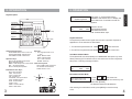
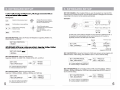
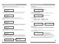
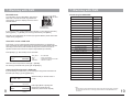
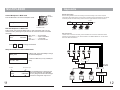
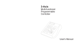
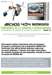
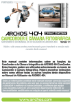
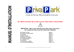
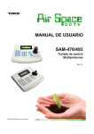
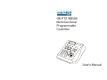
OKINA
OK-PTZ-KB300
Multi-functional
Programmable
Controller
OK-P
TZ-K
B300
User's Manual
WARNING
TO REDUCE THE RISK OF FIRE OR ELECTRIC SHOCK, DO NOT EXPOSE THIS PRODUCT TO
RAIN OR MOISTURE. DO NOT INSERT ANY METALLIC OBJECTS THROUGH THE VENTILATION
GRILLS OR OTHER OPENINGS ON THE EQUIPMENT.
This symbol indicates that dangerous
voltage constituting a risk of electric
shock is present within this unit.
CAUTION: TO REDUCE THE RISK
OF ELECTRIC SHOCK, DO NOT
REMOVE COVER ( OR BACK). NO
USER SERVICEABLE PARTS
INSIDE. REFER SERVICING TO
QUALIFIED SERVICE
PERSONNEL
This symbol indicates that there are
important operating and maintenance
instructions in the literature
accompanying this unit.
1. Precaution......................................................
2. Features.........................................................
3. Packing list.....................................................
4. Connection.....................................................
5. Operation.......................................................
6. Keyboard Setup..............................................
7. Woking with PTZ.............................................
8. Working with DVR...........................................
9. Working with Multiplexer..................................
10. Connection ...............................................
1
2
2
2
3
5
6
9
11
12
FCC COMPLIANCE STATEMENT
FCC INFORMATION: THIS EQUIPMENT HAS BEEN TESTED AND FOUND TO COMPLY WITH THE LIMITS FOR A
CLASS A DIGITAL DEVICE, PURSUANT TO PART 15 OF THE FCC RULES. THESE LIMITS ARE DESIGHEND TO
PROVIDE REASONABLE PROTECTION AGAINST HAMRFUL INTERFERENCE WHEN THE EQUIPMENT IS
OPERATED IN A COMMERCIAL ENVIRONMENT. THIS EQUIPMENT GENERATES, USES, AND CAN RADIATE
RADIO FREQUENCY ENGERGY AND IF NOT INSTALLED AND USED IN ACCORDANCE WITH THE
INSTRUCTION MANUAL, MAY CAUSE HARMFUL INTERFERENCE TO RADIO COMMUNICATIONS.
OPERATION OF THIS EQUIPMENT IN A RESIDENTIAL AREA IS LIKELY TO CAUSE HARMFUL INTERFERENCE
IN WHICH CASE THE USER WILL BE REQUIRED TO CORRECT THE INTERFERENCE AT HIS OWN EXPENSE.
CAUTION: CHANGES OR MODIFICATIONS NOT EXPRESSLY APPROVED BY THE PARTY RESPONSIBLE FOR
COMPLIANCE COULD VOID THE USERS‘S AUTHORITY TO OPERATE THE EQUIPMENT.
CE COMPLIANCE STATEMENT
WARNING: THIS IS A CLASS A PRODUCT. IN A DOMESTIC ENVIRONMENT THIS PRODUCT MAY CAUSE RADIO
INTERFERENCE IN WHICH CASE THE USER MAY BE REQUIRED TO TAKE ADEQUATE MEASURES.
This Symbol indicates that this product should not be treated as household
waste. When discarding this product, it must be sent to appropriate facilities for
recycling or recovery. By separating this product from other household waste,
you are helping to reduce the volume of waste incinerators and the natural
resource will be conserved.
CAUTION: BEFORE ATTEMPTING TO CONECT OR OPERATE THIS PRODUCT, PLEASE READ THE
LABEL ON THE BOTTOM AND USER'S MANUAL CAREFULLY
Technical specification are subjects to change without prior notice. This
Manual may contain printing or clerical errors. All trademarks mentioned
belong to their respective owners.
ENGLISH
CONTENTS
5. OPERATION
5. OPERATION
-Vxx<01>
System Keyboard
LCD Display
with back light
Operation
Keys
OK-PTZ-KB300
DVR
MUX
MENU
SET
Power
Rx
Tx
DVR
MUX
SYS
SHOT
Extended
Function Keys
Camera
Operation Keys
Digit pad
3-Axis Joystick
MON--001
CAM0001
After power on, keyboard will start the
initialization and self-test. The LC-Display will
show initial screen. Press Menu to start the
operation.
ALM- Operation Screen:
0001 MON: Selected Monitor
CAM: Selected Camera
ALM: Selected Alarm input.
Keyboard Sounds
The keyboard provides acustic signal when a button is pressed. Depends on
application it can be activated or deactivated:
1. Turn ON the Keyboard Sounds: Press ON
Camera Operation Keys:
Zoom WIDE/ TELE : Zoom-in and -out
FOCUS FAR/ NEAR : Manual focus
IRIS OPEN/ CLOSE : Manual irisl
Digit pad:
0-9 : Digit input from 0 to 9
* : * Key
MON : Monitor switch
CAM : Camera switch
CLR : Clear & Cancel
ENTER : Enter key
Operation Keys:
DVR : Enter the DVR control mode
MUX : Multiplexer mode
MENU : Enter setup menu or PTZ mode 3-Axis PTZ Joystick:
SET : Set preset position
LEFT / RIGHT: Pan movement
SHOT : Recall preset position
UP / DOWN: Tilt movement
TURN: Zoom in / Out
Extended Function Keys:
ALM : Alarm Function
GRP : Tour function
UP
OFF : Function Off
TELE
LEFT
ON : Function on
AUTOPAN : Auto pan function
RIGHT
ZOOM
AUX : Auxiliary function
DOWN
WIDE
RUN : Function Start
HOLD : Hold
PREV : Previous device
NEXT : Next device
3
ENGLISH
Key Description
+
2. Turn OFF the Keyboard Sounds: Press OFF +
1 at the same time
1
at the same time
User Mode & Admin Mode
The keyboard will enter automatically into USER MODE after power up, which
allows performing PTZ and DVR control, and restrict user access to keyboard
setup menu. Following message will show:
ADMIN AUTHORITY
001
0001
0001
Enter Administrator Mode:
PASSWORD:
**********
1. Press ON
+
2 at the same time
2. enter your password with the number key and
confirm with [ENTER]
The Default Password is 9876543210
After entering the Administrator mode, press [MENU] to enter the setup
menu
4
5. KEYBOARD SETUP
6.Working with PTZ
SET KEY ID: Set up the ID of the controller from 01 to 63.
Input the No. by digit-key. After setting, press ENTER to save or CLR to exit the
setting.
Start PTZ mode
By default, the keyboard usually starts in PTZ mode (display shows as below). You can
also press [MENU] to change to PTZ mode.
SET KEY ID
>01<01 63>
MON--001
SET KEY LEVEL: Set up the control levels of the controller from 00 to 15. Input the
No. by digit-key. After setting, press ENTER to save or CLR to exit the setting.
SET KEY LEVEL
>01<00 15>
SET MON RANGE
>0000 0239
0001
Change selected camera
Preset function
Add Preset
[SET] + n + [ENTER]. n= 1 to 255*
Call a preset: [SHOT] + n + [ENTER]. n= 1 to 255*
Delete a preset: [CLR] + n + [ENTER]. n= 1 to 255*
SET + n
001
0001
0001
SHOT + n
001
0001
0001
A sequence can store up to 24 preset points with individual dwell time and speed. You
can store a sequence by using this function. ( only availiable in B01 / B02 Protocol)
SET ALM RANGE: Set up the range of alarm positions from 0000 to 9999.
Input the No. by digit-key. After setting, press ENTER to save or CLR to exit the
setting.
SET ALM RANGE
>0000 9999
Press [GRP] + n + [SET]. n= 1 to 4
After entering sequence programming mode, the display shows the preset input and
setting for speed and time.
Seq: Sequence number
Pos: Preset number
Spd: Move speed between 1-8
Ti: Stop time between 0-60 sec
Press [ENTER] to confirm and save the
setting.
Repeat the preset pos input with speed and time setting, and confirm with enter. After
exiting the programming mode, the settings will be saved to dome's memory.
Seq
001
RESET DEFAUL_I?: Set the keyboard setting to factory default.(default password:
is "0123456789". Press ENTER to reset or CLR to exit. This process can take up to
30 sec. till the controller is available again. Note that after Baud-Rate changing, its is
necessary to restart the keyboard.
**********
0001
Tour - Sequence
SET CAM RANGE
>0000 9999
7
PTZ Mode
*The maximum preset number depends on the PTZ device. Please refer to the user's manual for further
information.
SET CAM RANGE: Set up the range of intelligent dome cameras from 0000 to 9999.
Input the No. by digit-key. After setting, press ENTER to save or CLR to exit the
setting.
RESET DEFAULT_I?
ALM0001
Select / Change current camera
You can change the camera by pressing [CAM] + n + [ENTER]. N represents the
channel number which should be selected
CAM + n
001
SET MON RANGE: Set up the range of monitors from 0000 to 0239.
Input the No. by digit-key. After setting, press ENTER to save or CLR to exit the
setting.
CAM0001
Pos
000
Spd Ti
000 000
RESET DEFAULT_I?
PLEASE WAIT . . .
8
7. Working with DVR
6.Working with PTZ
7. Working with DVR
Enter DVR mode
Function key for NVIDO DVR
To control DVR, press the DVR-Button and enter the
DVR-mode. The LED with "DVR" tag indicates the
current status, and the LC Display shows the current
selected DVR ID:
OK-PTZ-KB300
DVR
MUX
MENU
SET
Power
Rx
Tx
DVR
MUX
SYS
LED for
DVR Mode
Function
Enter DVR Menu
DVR_ID:01
If you have more than 1 DVR installed and configured, you can switch to other ID by
pressing [NEXT] + n +[ENTER]. For returning to PTZ mode, press [MENU]
Depends on the DVR Model, the function keys might be different. please refer to later
chapter for key assignment.
Enter
4 Cut
Hold
16 Cut
Zoom
Wide/Tele Key
Aux
Start Recording
ALM
Playback
Key Stop
In this mode, you can control the DVR and PTZ simultaneously: by selecting the
input on the DVR, the PTZ ID assigned to this channel will be automatically selected
and ready for PTZ control ( DVR and PTZ ID assignment need to be set prior to
operation. Please refer to the former chapter "Keyboard Setup" for details.)
Press [DVR] key (in DVR mode) to enter virtual PTZ
IN:01
Cam:0001
Switch the camera input channel: Press [N]* + [ENTER]
For returning to the DVR mode, press again the [DVR] key.
If you are already in Admin-mode, you can change the assignment of the PTZ ID to
the DVR input directy by pressing [NEXT] key.
GRP
OFF
Keyboard Infomation
Power ON/OFF DVR
Ch. Display 1N (N=0-9)
DVR ID
ID:01
IN:01
9
DVR Input Channel
Run
*
1+N+ Enter
0+N+Enter
Key Plus
3D Joystick Right
Key Minus
3D Joystick Left
Key Audio
Focus Near
Key Search
Key Next
Keylock
Focus Far
DVR ID Setting
CLR
SHOT
Key Left
Joystick Left
Key Right
Joystick Right
Key Up
Select the DVR you need to control or
modify
Set DVR ID:
01 < 00 99>
IRIS Open
Key Forward
Clear Keyboard screen
Change the PTZ assignment in DVR mode
ON
Autopan
Key Rewind
Ch. Display 0N (N=1-9)
DVR_ID:01.........ID of the DVR
IN:01...................Input 1 of the DVR
PTZ.....................Indicates the virtual PTZ mode
Cam:0001...........Camera or PTZ ID
Prev
IRIS close
Slow playback
Key Pause
Virtual PTZ control in DVR mode
Set
Enter Key
9 Cut
Press Button to
enter DVR mode
DVR_ID:01
PTZ
Key
SHOT
Key Down
Joystick Up
Joystick Down
output to matrix
OUT:0001
CAM:0001
Assign to
Camera ID
Press again [NEXT to ]Change the
assignment for DVR input and
camera ID ( admin access required)
Note:
- please setup the communication baud-rate and ID in the DVR correctly before connection.
- To prevent signal interference, it is strongly recommended to use RS-485 distributor for
connection
10
Appendix
MULTIPLEXER
Control Multiplexer in MUX mode
Press the MUX button to enter the Multiplexer mode.
OK-PTZ-KB300
DVR
MUX
MENU
SET
Power
Rx
Tx
DVR
MUX
SYS
LED for
MUX Mode
SHOT
RS-485 Termination
Devices using RS485 control are usually connected in daisy-chain. which reqiuers
termination with 120 Ω resistor on both ends. Following picture illustrates the connection
methods. please note that a daisy-chain connection type shall not exceed 7 meters.
RS 485+
RS485
Distributor
MUX_ID:01
120 Ω
OK-P
PTZ with Multiplexer in MUX mode
IN:01
Cam:0001
MUX_ID:01
PTZ
N +
TZ-KB
300
OK-P
TZ-KB
OK-P
TZ-KB
300
Press Button to
enter MUX mode
In MUX mode, press the button [MUX] again, to enter virtual PTZ mode. You can
control the PTZ by switching the input channel. the camera ID will also be switched
accordingly
Press
Resistor
RS 485-
MUX_ID:01.........ID of the MUX
IN:01...................Input 1 of the MUX
PTZ..................... Control PTZ
Cam:0001...........ID of the Camera
Device 1
Device 2
300
Device 3
Star-Connection
The star-form connection is mostly used. it enables the connection of different dome
cameras in longer distance. It is recommended to use RS485 distributor to ensure the
telemetric data transmission:
Enter to change the channel
Setup the virtual PTZ control in MUX mode
MUX_ID:01
In MUX mode, press [AUTOPAN] to change
the selected Multiplexer
Set MUX ID:
01 < 00 66>
2. Select the MUX ID ( if many installed) for
setup.
RS485
Rs485
Distributor
RS485
ID of MUX
ID:01
IN:01
DVR
Monitor ID for output
Press [AUTOPAN] again to setup the PTZ.
OUT:0001 (admin access required). press [ENTER]
CAM:0001 after every assignment to save the changes.
OK-P
TZ-KB
OK-P
TZ-KB
300
OK-P
300
TZ-KB
300
Video
Distributor
otherwise the configuration may be lost.
MUX CH ID
11
Camera ID
12