1
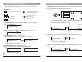
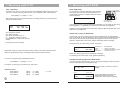
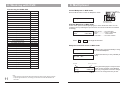
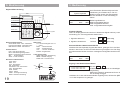
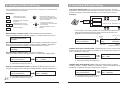
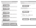
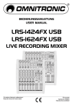
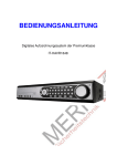
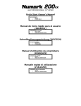
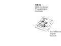
KB3N
Multi-functional
Programmable
Controller
User's Manual
English
Deutsch
WARNING
TO REDUCE THE RISK OF FIRE OR ELECTRIC SHOCK, DO NOT EXPOSE THIS PRODUCT TO
RAIN OR MOISTURE. DO NOT INSERT ANY METALLIC OBJECTS THROUGH THE VENTILATION
GRILLS OR OTHER OPENINGS ON THE EQUIPMENT.
This symbol indicates that dangerous
voltage constituting a risk of electric
shock is present within this unit.
CAUTION: TO REDUCE THE RISK
OF ELECTRIC SHOCK, DO NOT
REMOVE COVER ( OR BACK). NO
USER SERVICEABLE PARTS
INSIDE. REFER SERVICING TO
QUALIFIED SERVICE
PERSONNEL
This symbol indicates that there are
important operating and maintenance
instructions in the literature
accompanying this unit.
1. Precaution......................................................
2. Features.........................................................
3. Packing list.....................................................
4. Connection.....................................................
5. Operation.......................................................
6. Keyboard Setup..............................................
7. Woking with PTZ.............................................
8. Working with DVR...........................................
9. Working with Multiplexer..................................
10. Connection ...............................................
11. Notice...........................................................
1
2
2
2
3
5
8
10
12
13
14
FCC COMPLIANCE STATEMENT
FCC INFORMATION: THIS EQUIPMENT HAS BEEN TESTED AND FOUND TO COMPLY WITH THE LIMITS FOR A
CLASS A DIGITAL DEVICE, PURSUANT TO PART 15 OF THE FCC RULES. THESE LIMITS ARE DESIGHEND TO
PROVIDE REASONABLE PROTECTION AGAINST HAMRFUL INTERFERENCE WHEN THE EQUIPMENT IS
OPERATED IN A COMMERCIAL ENVIRONMENT. THIS EQUIPMENT GENERATES, USES, AND CAN RADIATE
RADIO FREQUENCY ENGERGY AND IF NOT INSTALLED AND USED IN ACCORDANCE WITH THE
INSTRUCTION MANUAL, MAY CAUSE HARMFUL INTERFERENCE TO RADIO COMMUNICATIONS.
OPERATION OF THIS EQUIPMENT IN A RESIDENTIAL AREA IS LIKELY TO CAUSE HARMFUL INTERFERENCE
IN WHICH CASE THE USER WILL BE REQUIRED TO CORRECT THE INTERFERENCE AT HIS OWN EXPENSE.
CAUTION: CHANGES OR MODIFICATIONS NOT EXPRESSLY APPROVED BY THE PARTY RESPONSIBLE FOR
COMPLIANCE COULD VOID THE USERS‘S AUTHORITY TO OPERATE THE EQUIPMENT.
CE COMPLIANCE STATEMENT
WARNING: THIS IS A CLASS A PRODUCT. IN A DOMESTIC ENVIRONMENT THIS PRODUCT MAY CAUSE RADIO
INTERFERENCE IN WHICH CASE THE USER MAY BE REQUIRED TO TAKE ADEQUATE MEASURES.
This Symbol indicates that this product should not be treated as household
waste. When discarding this product, it must be sent to appropriate facilities for
recycling or recovery. By separating this product from other household waste,
you are helping to reduce the volume of waste incinerators and the natural
resource will be conserved.
CAUTION: BEFORE ATTEMPTING TO CONECT OR OPERATE THIS PRODUCT, PLEASE READ THE
LABEL ON THE BOTTOM AND USER'S MANUAL CAREFULLY
Technical specification are subjects to change without prior notice. This
Manual may contain printing or clerical errors. All trademarks mentioned
belong to their respective owners.
ENGLISH
CONTENTS
- Refer all work related to the installaion of this product to qualified service
personnel or system installers.
- Do not attemp to disassemble the appliance. To prevent electric shock, do not
remove screws or cover. There are no user-serviceable parts inside. Contact qualified
service personnel for maintenance
- Handle the appliance with Care.D o not strike or shake, as this may damage the
appliance. It should be protected against extreme pressure, vibration and humidity
during transportation and storage. Damages caused by improper transportation avoid
the warranty.
- Do not operate the apliance beyond its specified temperature, humidity or power
source ratings. Do not use the keyboard in an extreme environment where high
temperature or high humidity exists. Use it within -5°C to +40°C(23°F to 140°F) and a
humidity below 90%. The input power source is 9V-12V DC, and requires at least
500mA.
- Read this user's manual carefully before operating the appliance. Make sure that
local electric safty standard are followed when using or installing the appliance
- Do not install this Product in a flammable and explosive environment.
- Make sure that the installation is done according to your local electricity and
safety regulation
- Before installation and mentainence, make sure that the appliance is
disconnected from the power source.
2.FEATURES
The AU-KB3N is a multi-funcational, programable keyboard controller for Pan-Tilt-Zoom
device, Digital Video Recorder and Matrix devices, and can be programmed with individual
protocol setting for each connected device. It is equipped with a 3-Axis joystick for
performing Pan,Tilt and Zoom action with single hand.
Main Features
ENGLISH
1.PRECAUTION
- Manage up to 9999 devices*
- controls PTZ, DVR and Matrix in different protocol with pre-programmed setting
- 3-Axis joystick
- Multiplexer operation with DVR and PTZ
- Password-protected for administrative access
- Supports major telemetric protocols
- Dual serial interface with RS232 and RS485
- Supports major DVR brand
- variable PTZ Speed
- Aluminium finishing
- Ergonomic Design
3.PACKING LIST
Please unpack the equipment and make sure all listed items and accessories are included
in the box:
KB3N
Programmable
Keyboard Controller
- Do not use any power source other than 12V DC, in order to prevent damages to
this device. For details, please refer to the section "Specifications" for further details.
KB3
N
USER'S MANUAL
www.vido-europe.com
- Handle the device during the installation carfully. Falls or extreme vibration may
cause irrepairable damages and avoid the warranty.
1 X Controller
1 x Connection
Box
- Do not install or operate the appliance near any high-voltage devices or highvoltage cable. The safety distance should remain at least 50 m.
- This product should be operated indoor only.
1 x 4-Pin RS232 Clip
1 x 2-Pin RS485 Clip
1 x Keyboard Cable
AU-P12H
AC-DC Power
Supply
1x User Manual
4.CONNECTION
RS485 Serial
Interface
PTZ or
DVR
RS485 +
Description
RS485 -
12V DC
Power input
To
Keyboard
1
AU-VD-P12H
12V DC
Power supply
GND
RXD
TXD
GND
RS232 Serial
Interface
KB 3N
2
5. OPERATION
5. OPERATION
KB3N-Vxx<01>
System Keyboard
LCD Display
with back light
Operation
Keys
After power on, keyboard will start the
initialization and self-test. The LC-Display will
show initial screen. Press Menu to start the
operation.
KB3N
DVR
MUX
MENU
SET
Power
Rx
Tx
DVR
MUX
SYS
SHOT
Extended
Function Keys
Camera
Operation Keys
Digit pad
3-Axis Joystick
MON--001
CAM0001
ALM- Operation Screen:
0001 MON: Selected Monitor
CAM: Selected Camera
ALM: Selected Alarm input.
Keyboard Sounds
The keyboard provides acustic signal when a button is pressed. Depends on
application it can be activated or deactivated:
1. Turn ON the Keyboard Sounds: Press ON
Camera Operation Keys:
Zoom WIDE/ TELE : Zoom-in and -out
FOCUS FAR/ NEAR : Manual focus
IRIS OPEN/ CLOSE : Manual irisl
Digit pad:
0-9 : Digit input from 0 to 9
* : * Key
MON : Monitor switch
CAM : Camera switch
CLR : Clear & Cancel
ENTER : Enter key
Operation Keys:
DVR : Enter the DVR control mode
MUX : Multiplexer mode
MENU : Enter setup menu or PTZ mode 3-Axis PTZ Joystick:
SET : Set preset position
LEFT / RIGHT: Pan movement
SHOT : Recall preset position
UP / DOWN: Tilt movement
TURN: Zoom in / Out
Extended Function Keys:
ALM : Alarm Function
GRP : Tour function
UP
OFF : Function Off
TELE
LEFT
ON : Function on
AUTOPAN : Auto pan function
RIGHT
ZOOM
AUX : Auxiliary function
DOWN
WIDE
RUN : Function Start
HOLD : Hold
PREV : Previous device
NEXT : Next device
3
ENGLISH
Key Description
+
2. Turn OFF the Keyboard Sounds: Press OFF +
1 at the same time
1
at the same time
User Mode & Admin Mode
The keyboard will enter automatically into USER MODE after power up, which
allows performing PTZ and DVR control, and restrict user access to keyboard
setup menu. Following message will show:
ADMIN AUTHORITY
001
0001
0001
Enter Administrator Mode:
PASSWORD:
**********
1. Press ON
+
2 at the same time
2. enter your password with the number key and
confirm with [ENTER]
The Default Password is 9876543210
After entering the Administrator mode, press [MENU] to enter the setup
menu
4
6. KEYBOARD SETUP
6. KEYBOARD SETUP
In order to get all advantages and functions, it is strongly recommended to
setup your keyboard before operation.
SET DVR CHANNEL: When multiple DVRs are used, the keyboard can map the DVRchannel input to a certain PTZ's ID. Once the DVR's channel is changed, the PTZ which
responding to this channel will be selected automatically.
Navigation:
CLR
MENU
change the value or options
by turning the control-stick to
the LEFT or RIGHT end
Confirmation or save setting
ENTER
0
Example:
Return to the previous level
9
Digit input for changing
function value
Back to Menu
PTZ ID 1 to 16, DVR input 1-16
SET MUX PROTOCOL
>ROBOT
SET MTX BAUD RAT: Set up the Baud rat for Matrix. Supporting: 1200bps,2400bps,
4800bps, 9600bps and 19200 bps.Press ENTER to save or CLR to exit
PTZ ID 17 to 32, DVR input 1-16
In DVR mode, when DVR2 is selected and input channel is switched to No. 2,
the keyboard will automatically set the current camera to ID 18, which is
physically connect to the 2nd input of the DVR.
SET DVR:
>SET_PROTOCOL>
SET DVR:
>SET_CHANNEL>
ALL : >NVIDO
01 : >NVIDO
SET DVR BAUTRATE: Setup the baud rate for DVR:
Supported: 1200bps,2400bps, 4800bps, 9600bps and 19200 bps
ALL: Baud rate setting for all DVR ID
01: individual setting for DVR ID 01
OUT:0001
CAM:0001
ID:01
IN:01
DVR CH ID
Camera ID
mapped to DVR CH ID
SET CAM PROTOCOL: Setup the Protocol for CAM. Each camera can be program with
different Protocol. After setting, press ENTER to save or CLR to exit the setting.
ALL: Protocol setting for all DVR ID
01: individual setting for DVR ID 01
SET DVR:
>SET_BAUDRATE>
Monitor ID for output
DVR ID
RAT
SET DVR PROTOCOL: Setup the DVR Protocol.
Supported: NVIDO, VC, DSCP, HIK, TUMIN, MITSU, DH and INTLX
5
DVR 2
- Scroll the main menu
- Navigate the cursor between
the sub items
Move UP, DOWN, LEFT or
RIGHT.
SET MUX PROTOCOL: Setup the Protocol for Multiplexer. Supporting: ROBOT, VC,
SONY, BOSCH and PELCO.
SET MTX BAUD
>9600bps
DVR 1
KB 3N
ALL : >9600bps
0001 : >9600bps
SET CAM PROTOCOL
>SET_PROTOCOL>
ALL : >B02
0001 : >B02
ALL: Protocol setting for all CAMERA ID
01: individual setting for CAMERA ID 01
SET CAM BAUDRATE: Set up the Baud rate for CAM. Supported settings: 1200bps,
2400bps, 4800bps, 9600bps and 19200 bps. After setting, press ENTER to save or
CLR to exit the setting.
SET CAM PROTOCOL
>SET_BAUDRATE>
ALL : >9600bps
0001 : >9600bps
ALL: Protocol setting for all CAMERA ID
01: individual setting for CAMERA ID 01
6
6. KEYBOARD SETUP
7.Working with PTZ
SET KEY ID: Set up the ID of the controller from 01 to 63.
Input the No. by digit-key. After setting, press ENTER to save or CLR to exit the
setting.
Start PTZ mode
By default, the keyboard usually starts in PTZ mode (display shows as below). You can
also press [MENU] to change to PTZ mode.
SET KEY ID
>01<01 63>
SET KEY LEVEL: Set up the control levels of the controller from 00 to 15. Input the
No. by digit-key. After setting, press ENTER to save or CLR to exit the setting.
SET KEY LEVEL
>01<00 15>
MON--001
CAM0001
ALM0001
PTZ Mode
Select / Change current camera
You can change the camera by pressing [CAM] + n + [ENTER]. N represents the
channel number which should be selected
SET MON RANGE: Set up the range of monitors from 0000 to 0239.
Input the No. by digit-key. After setting, press ENTER to save or CLR to exit the
setting.
CAM + n
001
SET MON RANGE
>0000 0239
SET CAM RANGE: Set up the range of intelligent dome cameras from 0000 to 9999.
Input the No. by digit-key. After setting, press ENTER to save or CLR to exit the
setting.
SET CAM RANGE
>0000 9999
Change selected camera
0001
0001
Preset function
Add Preset
[SET] + n + [ENTER]. n= 1 to 255*
Call a preset: [SHOT] + n + [ENTER]. n= 1 to 255*
Delete a preset: [CLR] + n + [ENTER]. n= 1 to 255*
SET ALM RANGE: Set up the range of alarm positions from 0000 to 9999.
Input the No. by digit-key. After setting, press ENTER to save or CLR to exit the
setting.
*The maximum preset number depends on the PTZ device. Please refer to the user's manual for further
information.
SET ALM RANGE
>0000 9999
RESET DEFAUL_I?: Set the keyboard setting to factory default.(default password:
is "0123456789". Press ENTER to reset or CLR to exit. This process can take up to
30 sec. till the controller is available again. Note that after Baud-Rate changing, its is
necessary to restart the keyboard.
RESET DEFAULT_I?
7
**********
SET + n
001
0001
0001
SHOT + n
001
0001
0001
RESET DEFAULT_I?
PLEASE WAIT . . .
8
7.Working with PTZ
7. Working with DVR
6.Working with PTZ
Tour - Sequence
Enter DVR mode
A sequence can store up to 24 preset points with individual dwell time and speed. You
can store a sequence by using this function. ( only availiable in B01 / B02 Protocol)
To control DVR, press the DVR-Button and enter the
DVR-mode. The LED with "DVR" tag indicates the
current status, and the LC Display shows the current
selected DVR ID:
Press [GRP] + n + [SET]. n= 1 to 4
After entering sequence programming mode, the display shows the preset input and
setting for speed and time.
Seq
001
Pos
000
KB3N
DVR
MUX
MENU
SET
Power
Rx
Tx
DVR
MUX
SYS
LED for
DVR Mode
SHOT
DVR_ID:01
Press Button to
enter DVR mode
If you have more than 1 DVR installed and configured, you can switch to other ID by
pressing [NEXT] + n +[ENTER]. For returning to PTZ mode, press [MENU]
Spd Ti
000 000
Depends on the DVR Model, the function keys might be different. please refer to later
chapter for key assignment.
Seq: Sequence number
Pos: Preset number
Spd: Move speed between 1-8
Ti: Stop time between 0-60 sec
Press [ENTER] to confirm and save the
setting.
In this mode, you can control the DVR and PTZ simultaneously: by selecting the
input on the DVR, the PTZ ID assigned to this channel will be automatically selected
and ready for PTZ control ( DVR and PTZ ID assignment need to be set prior to
operation. Please refer to the former chapter "Keyboard Setup" for details.)
Press [CLR] to exit the setting
Press [DVR] key (in DVR mode) to enter virtual PTZ
Virtual PTZ control in DVR mode
DVR_ID:01
PTZ
IN:01
Cam:0001
Repeat the preset pos input with speed and time setting, and confirm with enter. After
exiting the programming mode, the settings will be saved to dome's memory.
DVR_ID:01.........ID of the DVR
IN:01...................Input 1 of the DVR
PTZ.....................Indicates the virtual PTZ mode
Cam:0001...........Camera or PTZ ID
Switch the camera input channel: Press [N]* + [ENTER]
For returning to the DVR mode, press again the [DVR] key.
To start a tour please use the following command:
Change the PTZ assignment in DVR mode
If you are already in Admin-mode, you can change the assignment of the PTZ ID to
the DVR input directy by pressing [NEXT] key.
Press [GRP] + n + [RUN]. n= 1 to 4
To stop the a running tour, just perform any PTZ action.
Select the DVR you need to control or
modify
Set DVR ID:
01 < 00 99>
Plattern function
Start Plattern:
Stop Plattern:
Run Plattern:
9
[Shot]
[Shot]
[Shot]
+ n + [ON]
+ n + [OFF]
+ n + [RUN]
n= 1 to 4
DVR ID
ID:01
IN:01
DVR Input Channel
output to matrix
OUT:0001
CAM:0001
Assign to
Camera ID
Press again [NEXT to ]Change the
assignment for DVR input and
camera ID ( admin access required)
10
8. Working with DVR
9. Multiplexer
Function key for NVIDO DVR
Function
Enter DVR Menu
Key
Control Multiplexer in MUX mode
Set
Press the MUX button to enter the Multiplexer mode.
Enter Key
Enter
4 Cut
Hold
9 Cut
Prev
16 Cut
Wide/Tele Key
Slow playback
Aux
Start Recording
ALM
Playback
Key Pause
Key Stop
ON
Autopan
IRIS Open
Key Rewind
GRP
Key Forward
OFF
Keyboard Infomation
Power ON/OFF DVR
Ch. Display 1N (N=0-9)
Ch. Display 0N (N=1-9)
*
0+N+Enter
Key Minus
3D Joystick Left
Key Audio
Focus Near
Clear Keyboard screen
SET
DVR
MUX
SYS
LED for
MUX Mode
SHOT
MUX_ID:01
Press Button to
enter MUX mode
PTZ with Multiplexer in MUX mode
In MUX mode, press the button [MUX] again, to enter virtual PTZ mode. You can
control the PTZ by switching the input channel. the camera ID will also be switched
accordingly
IN:01
Cam:0001
MUX_ID:01
PTZ
MUX_ID:01.........ID of the MUX
IN:01...................Input 1 of the MUX
PTZ..................... Control PTZ
Cam:0001...........ID of the Camera
Press
N +
Enter to change the channel
Setup the virtual PTZ control in MUX mode
MUX_ID:01
In MUX mode, press [AUTOPAN] to change
the selected Multiplexer
Set MUX ID:
01 < 00 66>
2. Select the MUX ID ( if many installed) for
setup.
Focus Far
DVR ID Setting
CLR
Keylock
SHOT
Key Left
Joystick Left
Key Right
Joystick Right
Key Up
Joystick Up
Key Down
MENU
Tx
1+N+ Enter
3D Joystick Right
Key Search
MUX
Rx
Run
Key Plus
Key Next
DVR
IRIS close
Zoom
KB3N
Power
Joystick Down
ID of MUX
ID:01
IN:01
Monitor ID for output
Press [AUTOPAN] again to setup the PTZ.
OUT:0001 (admin access required). press [ENTER]
CAM:0001 after every assignment to save the changes.
otherwise the configuration may be lost.
MUX CH ID
11
Note:
- please setup the communication baud-rate and ID in the DVR correctly before connection.
- To prevent signal interference, it is strongly recommended to use RS-485 distributor for
connection
Camera ID
12
10. Appendix
11. Note
RS-485 Termination
Devices using RS485 control are usually connected in daisy-chain. which reqiuers
termination with 120 Ω resistor on both ends. Following picture illustrates the connection
methods. please note that a daisy-chain connection type shall not exceed 7 meters.
RS 485+
RS485
Distributor
120 Ω
Resistor
RS 485KB3N
KB3N
Device 1
KB3N
Device 2
Device 3
Star-Connection
The star-form connection is mostly used. it enables the connection of different dome
cameras in longer distance. It is recommended to use RS485 distributor (e.g AU-VCMC2088) to ensure the telemetric data transmission:
RS485
Rs485
Distributor
RS485
DVR
KB3N
KB3N
KB3N
Video
Distributor
13
14
ACHTUNG
INHALT
Dieses Symbol warnt vor
Hochspannung und Kurzschlüssen.
Vorsicht: Entfernen Sie die
Abdeckung nicht!
Stromschläge oder
Beschädigungen des Gerätes
können die Folge sein.
Wenden Sie sich nur an
qualifiziertes Personal in
Dieses Symbol weist auf wichtige
Hinweise in der
Bedienungsanleitung hin.
1. Sicherheitsvorkehrungen..................................
2. Funktionen......................................................
3. Inhalt..............................................................
4. Verbindung......................................................
5. Bedienung.......................................................
6. Keyboard Einstellungen....................................
7. PTZ- Bedienung...............................................
8. DVR Bedienung...............................................
9. Multiplexer Bedienung......................................
10. Appendix.......................................................
11. Notize...........................................................
1
2
2
2
3
5
8
10
12
13
14
DEUTSCH
Um Feuer und Kurzschlüsse zu vermeiden bitte dieses Produkt nicht Regen oder
Feuchtigkeit aussetzen. Keine metallischen Gegenstände in die Lüftungsöffnungen
oder
FCC BEGLEITERKLÄRUNG
F C C I N F O R M AT I O N : D I E S E S G E R Ä T W U R D E G E T E S T E T U N D A L S
QUALITÄTSPRODUKT ANERKANNT,
BEZUGNEHMEND AUF ABSCHNITT 15 DER FCC REGELN. DIE GRENZEN LIEGEN
BEI SCHÄDLICHEN
INTERFERENZEN BEIM GEBRAUCH IN EINER KOMMERZIELLEN UMGEBUNG.
DIESES GERÄT
GENERIERT, GEBRAUCHT RADIAT RADIO FREQUENZ ENERGIEN UND WENN
DAS GERÄT NICHT
HINWEIS : Änderungen an diesem Gerät, die nicht von VIDO Electronic Vertriebs
GESmbH genehmigt wurden, können dazu führen, dass die FCC ihre Genehmigung
zurückzieht, sodass das Gerät nicht im Betrieb genommen werden darf.
ERKLÄRUNG ZUR EINHALTUNG DER CE VORSCHRIFTEN
HINWEIS: Es handelt sich um ein “CLASS A” Produkt. Dieses Produkt kann
Funkstörung verursachen. In diesem Fall muss
der Benutzer erforderliche
Maßnahmen ergreifen.
Dieses Symbol zeigt an, dass dieses Produkt nicht als Sperrmüll behandelt
werden soll. Bei Entsorgung dieses Produktes beachten Sie bitte, dass es bei
einer fachgemäßen Institution recyclet wird. Bei angebrachter Trennung dieses
Produktes vom üblichen Sperrmüll helfen Sie Ihrer Umwelt damit.
HINWEIS: Vor der ersten Inbetriebnahme des Gerätes, auf die Warnhinweise achten und die
Anleitung sorgfältig durchlesen!
Änderung und Rechte aller Konstruktion und der technischen Daten vorbehalten.
Eventuell genannte Marken oder Produktnamen sind Warenzeichen oder
eingetragene
16
- Überlassen Sie die installationsbezügliche Arbeiten ausschließlich
qualifiziertem Personal.
- Versuchen Sie nicht das Produkt selbst auseinander zu nehmen. Um elektrische
Schocks zu vermeiden, bitte keine Schrauben oder die Abdeckung entfernen. Es
befinden sich keine Ersatzteile im Inneren, in den Sie austauschen können.
Kontaktieren Sie qualifiziertes Personal für Wartungen.
- Behandeln Sie die Gerät mit Sorgfalt. Setzen Sie dieses Gerät keinem extremen
Druck, Vibration oder Feuchtigkeit aus, sowohl während der Lieferung als auch im
Lager. Die Garantie erlischt bei Schäden die durch unsachgemäße Benutzung
entstehen.
- Bedienen Sie die Gerät ausschließlich in den dafür vorgesehenen Temperatur-,
Feuchtigkeits- & Strombereichen. Setzen Sie dieses Gerät keinem Gebiet ein wo
hohe Temperatur und Feuchtigkeit herrscht. Für die Temperatur gilt -5°C bis
+40°C(23°F bis 140°F) und für die Feuchtigkeit unter 90%. Die Energiequelle beträgt
9V-12V DC, und benötigt mindestens 500mA.
- Lesen Sie bitte das Handbuch sorgfältig durch bevor sie das Gerät benutzen.
Vergewissern Sie sich, dass der elektrische Sicherheitsstandard gewährleistet ist bei
der Benutzung oder Installation der Anwendung.
- Installieren Sie dieses Produkt in keiner feuergefährlichen oder explosiven
Gegend.
- Vergewissern Sie sich das die Installation sachgemäß nach der lokalen
elektrischen Sicherheits Regelung durchgeführt wird.
2.Funktionen
AU-KB3N ist ein Multi-Funktions, programmierbares Keyboard das zur Steuerung von
Speed-Dome, Zoom Kameras, PTZ Geräten und Matrix Vorrichtungen dient. Weiters
kann jede Vorrichtung die mit der Anwendung verbunden ist einzeln mit den
Protokolleinstellungen programmiert werden. Das Gerät ist mit einem 3-Achsen Joystick
ausgestattet um Schwenkungen, Neigungen und Zoom Aktionen bequem mit einer Hand
durchzuführen.
Merkmale
- Kontrolliert bis zu 9999 Vorrichtungen*
- Kontrolliert PTZ, DVR und Matrix in verschiedenen Protokollen mit einer
vorprogrammierten Einstellung.
- 3-Achsen Joystick
- Multiplexeranwendung mit DVR und PTZ
- Passwortgeschützt für administrative Zugänge
- Unterstützt hauptsächlich telemetrische Protokolle
- Verbindungsschnittstelle mit RS232 und RS485
- Unterstützt die am häufigst verwendeten DVR Marken
DEUTSCH
1.Sicherheitsvorkehrungen
3.Inhalt
Bitte vergewissern Sie sich nach der Öffnung der Schachtel, dass der Inhalt der
Gegenstände mit der Auflistung komplett übereinstimmen.
KB3N
Programmable
Keyboard Controller
- Vor der Installation und Wartungsarbeiten, stellen Sie bitte fest ,dass das Gerät
nicht unter Spannungsquelle mehr verbunden ist.
KB3
N
USER'S MANUAL
www.vido-europe.com
- Verwenden Sie keine andere Spannungsquelle außer 12V DC, um Schäden an
dieser Anwendung zu vermeiden. Für weitere Details, schlagen Sie bitte im
Abschnitt "Spezifikationen" nach.
- Behandeln Sie das Gerät während der Installation mit Vorsicht. Bei Sturz oder
extremen Vibrationen könnten Schäden entstehen wodurch die Garantie ungültig
wird.
- Installieren und Bedienen Sie diese Anwendung nicht in der Nähe von einer
Hochspannungsvorrichtung. Der Sicherheitsabstand sollte 50m betragen.
- Dieses Produkt sollte ausschließlich im Indoor-Bereich angewendet werden.
1 X Keyboard
1 x Anschlußkasten 1 x 4-Pin RS232 Clip
1 x 2-Pin RS485 Clip
1 x Verbindungskabel
AU-P12H
12V DC
Netzteil
1x Handbuch
4.Verbindung
RS485 serielle
Schnittstelle
PTZ oder
DVR
RS485 +
Beschreibung
RS485 -
12V DC
Spannungeingang
Zum
Keyboard
17
AU-VD-P12H
12V DC
Netzteil
GND
RXD
TXD
GND
RS232 serielle
Schnittstelle
KB 3N
18
5. Bedienung
5. Bedienung
Keyboard Beschreibung
LCD Display
mit Hintergrundlicht
Funktionstasten
ErweiterteFunktionstasten
KB3N
DVR
MUX
MENU
SET
Power
Rx
Tx
DVR
MUX
SYS
SHOT
Kamera
Funktionstasten
Zahlen Pad
3-Achsen Joystick
Kamera Funktionstasten:
Zahlen Pad:
Zoom WIDE/ TELE : Nah- & Weitzoom
0-9 : Nummerneingabe von 0-9
FOCUS FAR/ NEAR : manueller Fokus
* : * Taste
IRIS OPEN/ CLOSE : manuelle Iris
MON : Monitorwechsel
CAM : Kamerawechsel
Funktionstasten:
CLR
: Löschen & Abbruch
DVR : DVR Kontrollmodus
ENTER : Eingabetaste
MUX : Mehrfachkoppelungsmodus
MENU : Hauptmenü oder PTZmodus
3-Axis PTZ Joystick:
SET : Punkt festlegen
LINKS / RECHTS: Schwenkung
SHOT : Punkt anvisieren
OBEN / UNTEN: Neigung
TURN: Rein- & Rauszoomen
Erweiterte Funktionstasten:
ALM : Alarm
GRP : Tour
OBEN
OFF : Ausschalten
TELE
LINKS
ON : Einschalten
AUTOPAN : Auto- Schwenken
RECHTS ZOOM
AUX : Zusatzfunktion
UNTEN
WIDE
RUN : Starten
HOLD : Halten
PREV : Vorherige Vorrichtung
NEXT : Nächste Vorrichtung
19
MON--001
CAM0001
DEUTSCH
Nach Einschalten führt das Keyboard eine
Initialisierung und Testlauf durch. Der LCBildschirm zeigt danach das Einstiegsbild.
Drücken Sie Menü um die Anwendung zu
starten.
KB3N-Vxx<01>
System Keyboard
ALM- Bedienungsbildschirm:
0001 MON: ausgewählter Monitor.
CAM: ausgewählte Kamera.
ALM: ausgewählte Alarmeingabe.
Keyboard Signale
Wenn ein Knopf gedrückt wird ertönt ein akustisches Signal welches je nach
Anwendung ein- oder ausgeschaltet werden kann.
1. Signalton aktivieren:
Drücken
ON
+
1 gleichzeitig
2. Signalton deaktivieren:
Drücken
OFF +
1 gleichzeitig
Benutzer Modus & Administrator Modus
Nachdem Sie das Keyboard eingeschaltet haben, gelangen Sie in den Benutzer
Modus in dem Ihnen die PTZ und DVR Steuerung ermöglicht wird. Der Zugriff in
den Administrator Modus wird Ihnen verweigert und folgende Nachricht scheint
auf:
ADMIN AUTHORITY
001
0001
0001
Zugang in den Administrator Modus:
PASSWORD:
1. Drücken ON +
2
**********
2.Geben Sie Ihr Passwort ein und bestätigen Sie
mit [ENTER].
Mit diesem Passwort: 9876543210 können Sie
sich erstmalig einloggen
Nachdem Sie in den Administrator Modus angelangt sind, drücken Sie [MENU]
um in das Hauptmenü zu gelangen.
20
6. Keyboard Einstellung
6. Keyboard Einstellung
Um alle Möglichkeiten optimal nutzen zu können, empfehlen wir das Keyboard
vor der Anwendung einzustellen.
DVR KANAL EINSTELLUNG: Wenn mehrere DVRs benutzt werden, ,kann das
keyboard mit dem entsprechenden DVR kanal die PTZ ID ansprechen. Once the DVR's
channel is changed, the PTZ which responding to this channel will be selected
Navigation:
CLR
ENTER
Bestätigen oder Eingabe
speichern
0
MENU
9
Zahleneingabe um den
Funktionswert zu ändern
Zurück zu Menü
Beim Drehen des ControlSticks nach links oder rechts
können Sie den Wert oder die
Option verändern.
- Scroll the main menu
- Navigate the cursor between
the sub items
Move UP, DOWN, LEFT or
RIGHT.
MUX PROTOKOLL EINSTELLUNG: Protokolleinstellung für den Multiplexer.
Folgende Protokolle werden unterstützt: ROBOT, VC, SONY, BOSCH and PELCO.
SET MUX PROTOCOL
>ROBOT
MTX BAUD RATE EINSTELLUNG: Baud Rate Einstellung für die Matrix. Folgende
Übertragungsraten werden unterstützt: 1200bps,2400bps, 4800bps, 9600bps and
19200 bps.Sie speichern mit ENTER und verlassen das Menü mit CLR.
SET MTX BAUD
>9600bps
RAT
DVR PROTOKOLL EINSTELLUNG: DVR Protocol Einstellung.
Folgende Protokolle werden unterstützt: NVIDO, VC, DSCP, HIK, TUMIN, MITSU,
SET DVR:
>SET_PROTOCOL>
ALL : >NVIDO
01 : >NVIDO
ALL: Protokolleinstellung für alle DVR ID
01: Individuelle Einstellung für DVR ID 01
EINSTELLUNG DER DVR BAUTRATE: Einstellung der Baud Rate für den DVR:
Folgende Protokolle werden unterstützt: 1200bps,2400bps, 4800bps, 9600bps and
SET DVR:
>SET_BAUDRATE>
21
ALL: Baud Rate Einstellung für alle DVR ID
01: Individuelle Einstellung für DVR ID 01
ALL : >9600bps
0001 : >9600bps
DEUTSCH
Example:
Gelangen Sie in das
vorhergehende Menü
DVR 1
KB 3N
RS485
Verteiler
PTZ ID 1 to 16, DVR input 1-16
DVR 2
PTZ ID 17 to 32, DVR input 1-16
Im DVR modus, wenn DVR2 gewählt wird und IP Kanal auf 2 gesetzt wird
wählt das keyboard automatisch die Kamera mit der ID 18 welche sich
physikalisch an der zweiten Stelle befindet.
Monitor ID for output
DVR ID
SET DVR:
>SET_CHANNEL>
OUT:0001
CAM:0001
ID:01
IN:01
DVR CH ID
Camera ID
mapped to DVR CH ID
KAMERA PROTOKOLL EINSTELLUNG: Jede Kamera kann einzeln mit einem eigenen
Protokoll eingestellt werden. Drücken Sie ENTER um die Einstellung zu speichern oder
CLR um das Menü zu verlassen.
SET CAM PROTOCOL
>SET_PROTOCOL>
ALL : >B02
0001 : >B02
ALL: Protokolleinstellung für alle Kameras ID
01: Individuelle Einstellung für KAMERA ID 01
KAMERA BAUD RATE EINSTELLUNG: Folgende Protokolle werden unterstützt:
1200bps, 2400bps, 4800bps, 9600bps and 19200 bps. Drücken Sie ENTER um die
Einstellung zu speichern oder CLR um das Menü zu verlassen.
SET CAM PROTOCOL
>SET_BAUDRATE>
ALL : >9600bps
0001 : >9600bps
ALL: Baud Rate Einstellung für alle Kameras ID
01: Individuelle Einstellung für Kamera ID 01
22
7. PTZ Bedienung
KEY ID EINSTELLUNG: Stellen Sie die ID des Kontrollgerätes von 01 bis 63 ein.
Geben Sie die Nr. über das Zahlenpad ein. Drücken Sie ENTER um die Einstellung
zu speichern oder CLR um das Menü zu verlassen.
PTZ Modus starten
Standardgemäß startet das Keyboard im PTZ Modus (siehe untere Abbildung). Beim
Drücken der MENU taste können Sie automatisch in den PTZ Modus gelangen.
SET KEY ID
>01<01 63>
KEY LEVEL EINSTELLUNG: Stellen Sie die Kontroll-Level des Keyboard von 00 bis
15 ein. Drücken Sie ENTER um die Einstellung zu speichern oder CLR um das Menü
zu verlassen.
MON--001
CAM0001
ALM0001
PTZ Mode
Wählen / Wechseln einer Kamera
Die Kamera kann gewechselt werden indem Sie [CAM] + n + [ENTER] drücken. N zeigt
den Kanal an, der gewählt werden soll.
SET KEY LEVEL
>01<00 15>
MON RANGE EINSTELLUNG: Stellen Sie die Reichweite des Monitors von 0000
bis 0239 ein. Drücken Sie ENTER um die Einstellung zu speichern oder CLR um das
Menü zu verlassen.
CAM + n
001
0001
0001
Kamera wechseln
SET MON RANGE
>0000 0239
CAM RANGE EINSTELLUNG: Stellen Sie die Reichweite von Dome-Kameras von
0000 bis 9999 ein. Drücken Sie ENTER um die Einstellung zu speichern oder CLR
um das Menü zu verlassen.
SET CAM RANGE
>0000 9999
Preset Funktion
Preset hinzufügen: [SET] + n + [ENTER]. n= 1 to 255*
Preset abrufen:
[SHOT] + n + [ENTER]. n= 1 to 255*
Preset löschen:
[CLR] + n + [ENTER]. n= 1 to 255*
*Die maximale preset Nummer hängt von dem PTZ Gerät ab.
ALM RANGE EINSTELLUNG: Stellen Sie die Reichweite der Alarmpositionen von
0000 bis 9999 ein. Drücken Sie ENTER um die Einstellung zu speichern oder CLR
um das Menü zu verlassen.
SET + n
001
SET ALM RANGE
>0000 9999
0001
0001
SHOT + n
001
0001
0001
RESET DEFAULT EINSTELLUNG: Die ursprünglichen Einstellungen werden wieder
hergestellt (Default password lautet: is "0123456789"). Drücken Sie ENTER um das
Keyboard zu reseten oder CLR um das Menü zu verlassen.Dieser Vorgang kann bis
zu 30 Sekunden dauern bis das Kontrollgerät wieder verfügbar ist. Beachten Sie,
dass nach einer Änderung der Baud-Rate ein Neustart des Keyboards erforderlich
ist.
RESET DEFAULT_I?
23 **********
RESET DEFAULT_I?
PLEASE WAIT . . .
24
DEUTSCH
6. Keyboard Einstellung
7. PTZ Bedienung
8. DVR Bedienung
6.Working with PTZ
Tour - Sequenz
DVR Modus starten
Eine Sequenz kann bis zu 24 preset Punkte speichern mit unterschiedlicher
Geschwindigkeit und Stopzeit. Eine Sequenz kann mit der folgenden Funktion
gespeichert werden: nur in B01/B02 Protokollen verfügbar.
Um den DVR zu steuern, drücken Sie bitte auf [DVR] .
Das LED mit der Kennzeichnung "DVR" zeigt Ihnen
den momentanen Status an und der LC Display zeigt
Ihnen die momentan ausgewählte DVR ID an.
MENU
SET
Power
Rx
Tx
DVR
MUX
SYS
LED für
DVR Mode
SHOT
“DVR” Taste
Nachdem Sie in den Sequence Programm Modus ist, zeigt Ihnen das Display den preset
Input und die Einstellungen für Geschwindigkeit und Zeit an.
Pos
000
MUX
DVR_ID:01
Press [GRP] + n + [SET]. n= 1 to 4
Seq
001
KB3N
DVR
Spd Ti
000 000
Falls Sie mehr als einen DVR installiert und konfiguriert haben, dann können Sie zu
den anderen DVR-IDs wechseln indem Sie [NEXT] + n +[ENTER] drücken. Um in
den PTZ Modus zurückzukehren, drücken Sie [MENU]
Abhänging vom DVR-Model kann es durchaus sein, dass die Funktionstasten anders
belegt sind. Schlagen Sie dazu bitte im Kapitel für Tastenbelegungen nach.
Virtuelle PTZ Steuerungl im DVR Modus
Dieser Modus ermöglicht Ihnen die Steuerung von einem DVR und PTZ zur gleichen
Zeit: indem Sie ein DVR auswählen, wird die PTZ ID, die dem Kanal zugeteilt wurde
ausgewählt und zur Steuerung bereitgestellt (DVR & PTZ ID müssen richtig
eingestellt sein, damit die Steuerung ermöglicht wird. Schlagen Sie dazu bitte im
vorherigen Kapitel unter “Keyboardeinstellungen” nach.)
Seq: Sequence Nummer
Pos: Preset Nummer
Spd: Bewegungsgeschwindigkeit
zwischen 1-8
Ti: Haltezeit der Preset von 0-60 sec
Drücken Sie ENTER um die Einstellung
zu speichern.
Um weitere Presets zu speichern, wiederholen Sie den Vorgang und bestätigen mit
ENTER.
DVR_ID:01
PTZ
IN:01
Cam:0001
DVR_ID:01.........ID des DVR
IN:01...................Eingabe 1 des DVR
PTZ.....................Virtueller PTZ Modus
Cam:0001...........Kamera oder PTZ ID
Um den Eingabekanal der Kamera zu wechseln drücken Sie [N]* + [ENTER]
Um in den DVR Modus zurückzukehren drücken Sie nochmal auf [DVR].
Um eine Tour zu starten geben Sie bitte folgenden Befehl ein:
Press [GRP] + n + [RUN]. n= 1 to 4
Änderung der PTZ Zuweisung im DVR Modus
Um eine laufende Tour zu beenden betätigen Sie das PTZ manuell.
Wenn Sie sich bereits im Administrator-Modus befinden, dann können Sie die
Zuweisung der PTZ ID zur DVR Eingabe direkt ändern indem Sie [NEXT] drücken.
Plattern Funktion
Start Plattern:
Stop Plattern:
Run Plattern:
[Shot]
[Shot]
[Shot]
+ n + [ON]
+ n + [OFF]
+ n + [RUN]
n= 1 to 4
DVR ID
ID:01
IN:01
25
Auswählen der DVR, welche Sie
ansteuern will
Set DVR ID:
01 < 00 99>
DVR Eingabekanal
Ausgang zur Matrix
OUT:0001
CAM:0001
Zugeteilte Kamera-ID
Durch das Wiederholen der Taste
[NEXT], wird das
Programmierungsmenü angezeigt(
26
8. DVR Bedienung
Funktionbefehl für DVR mit NVIDO Protokoll
Funktion
DVR Menu
Set
Enter Taste
Enter
4 Split
Hold
9 Sülit
Prev
16 Split
Zoom
Slow playback Taste
Aux
ALM
Play Taste
ON
Pause Taste
Autopan
IRIS Open
Rückspül Taste
GRP
Vorspül Taste
OFF
Keyboard Infomation
Run
Power ON/OFF DVR
Ch. Display 1N (N=0-9)
*
0+N+Enter
Plus Taste
3D Joystick Right
Minus Taste
3D Joystick Left
Audio Taste
Focus Near
Next Taste
Clear Keyboard screen
Keylock Taste
KB3N
DVR
MUX
MENU
SET
Power
Rx
Tx
DVR
MUX
SYS
LED für
MUX Mode
SHOT
MUX_ID:01
“MUX” Taste
PTZ mit Multiplexer im MUX Modus
Drücken Sie nochmals auf [MUX] um in den virtuellen PTZ Modus zu gelangen. Sie
können das PTZ steuern. Beim Wechseln des Eingabekanals wird auch die
dementsprechende Kamera-ID gewechselt
IN:01
Cam:0001
MUX_ID:01
PTZ
Press
N +
MUX_ID:01.........ID des MUX
IN:01...................Eingabe 1 des MUX
PTZ.....................PTZ Kontrolle
Cam:0001...........Kamera-ID
Enter to change the channel
Einstellung der virtuellen PTZ Kontrolle im MUX Modus
MUX_ID:01
Drücken Sie im MUX Modus [AUTOPAN]
um den Multiplexer zu wechseln
Set MUX ID:
01 < 00 66>
2. Wählen Sie die MUX ID (wenn mehrere
installiert) für die Einstellung
Focus Far
DVR ID Setting
CLR
SHOT
Left Taste
Joystick Left
Right Taste
Joystick Right
Up Taste
Joystick Up
Down Taste
Drücken Sie [MUX] um in den Multiplexer Modus
Zu gelangen.
1+N+ Enter
Ch. Display 0N (N=1-9)
Search Taste
Multiplexersteuerung im MUX Modus
IRIS close
Wide/Tele Key
Record Taste
Stop Taste
27
Taste
DEUTSCH
9. Multiplexer
Joystick Down
Beachten Sie bitte Folgendes:
- Stellen Sie bitte die Baud-Rate und ID des DVRs korrekt ein, bevor sie eine Verbindung starten.
- Um Signalstörungen zu vermeiden, empfehlen wir Ihnen für die Verbindung ein RS-485 Verteiler zu
verwenden.
ID of MUX
Monitor ID for output
ID:01
IN:01
OUT:0001
CAM:0001
MUX CH ID
Camera ID
Drücken Sie nochmals [AUTOPAN]
um das PTZ einzustellen.
(Adminrechte benötigt). Drücken Sie nach
jeder Zuweisung auf [ENTER] um die
Änderungen zu speichern, ansonsten gehen
die Konfigurationen verloren.
28
11. Notize
RS-485 Termination
Geräte die einen RS485 Verteiler zum Steuern benutzen, werden oft im “Daisy-Chain”System verbunden, welches einen 120 Ω Widerstandsanschluss an beiden Enden
benötigen. Die folgenden Abbildungen zeigen Ihnen einige Verbindungsmöglichkeiten.
Bitte beachten Sie das eine “Daisy-Chain” Verbindung keine 7 Meter überschreiten soll.
RS 485+
RS485
Verteiler
120 Ω Widerstand
DEUTSCH
10. Appendix
RS 485KB3N
KB3N
Gerät 1
KB3N
Gerät 3
Gerät 2
Star-Connection
Die “Star-Form Connection” ist das übliche System das benutzt wird. Diese ermöglicht Ihnen
die Verbindung mehrerer Kameras über weitere Strecken. Wir empfehlen Ihnen einen
RS485 Verteiler (z.B AU-VC-MC2088) zu verwenden um die telemetrische
Datenübertragung zu gewährleisten:
RS485
Verteiler
RS485
Verteiler
RS485
Verteiler
DVR
KB3N
KB3N
KB3N
Video
Verteiler
29
30