1
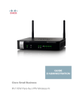
Wireless Controller
User Manual
DWC-1000
Version 3.11
Business Wireless Solution
Preface
D-Link reserves the right to revise this publication and to make changes in the content hereof without obligation to
notify any person or organization of such revisions or changes. Information in this document may become obsolete
as our services and websites develop and change.
Manual Revisions
Revision
Date
Description
3.10
October 16, 2014
DWC-1000 revision A1 with firmware 4.4.0.1
3.11
October 1, 2015
DWC-1000 revision A1/B1 with firmware 4.4.1.2
Trademarks
D-Link and the D-Link logo are trademarks or registered trademarks of D-Link Corporation or its subsidiaries in
the United States or other countries. All other company or product names mentioned herein are trademarks or
registered trademarks of their respective companies.
© 2015 D-Link Corporation.
All rights reserved. This publication may not be reproduced, in whole or in part, without prior expressed written
permission from D-Link Corporation.
D-Link DWC-1000 User Manual
2
Safety Instructions
Use the following safety guidelines to ensure your own personal safety and to help protect your system from
potential damage.
Safety Cautions
To reduce the risk of bodily injury, electrical shock, fire, and damage to the equipment, observe the following
precautions:
• Observe and follow service markings.
• Do not service any product except as explained in your system documentation.
• Opening or removing covers that are marked with the triangular symbol with a lightning bolt
may expose you to electrical shock.
• Only a trained service technician should service components inside these compartments.
• If any of the following conditions occur, unplug the product from the electrical outlet and replace the
part or contact your trained service provider:
• The power cable, extension cable, or plug is damaged.
• An object has fallen into the product.
• The product has been exposed to water.
• The product has been dropped or damaged.
• The product does not operate correctly when you follow the operating instructions.
• Keep your system away from radiators and heat sources. Also, do not block cooling vents.
• Do not spill food or liquids on your system components, and never operate the product in a wet
environment. If the system gets wet, see the appropriate section in your troubleshooting guide or
contact your trained service provider.
• Do not push any objects into the openings of your system. Doing so can cause fire or electric shock by
shorting out interior components.
• Use the product only with approved equipment.
• Allow the product to cool before removing covers or touching internal components.
• Operate the product only from the type of external power source indicated on the electrical ratings
label. If you are not sure of the type of power source required, consult your service provider or local
power company.
• Also, be sure that attached devices are electrically rated to operate with the power available in your
location.
• Use only approved power cable(s). If you have not been provided with a power cable for your system or
for any AC powered option intended for your system, purchase a power cable that is approved for use
in your country. The power cable must be rated for the product and for the voltage and current marked
on the product’s electrical ratings label. The voltage and current rating of the cable should be greater
than the ratings marked on the product.
• To help prevent electric shock, plug the system and peripheral power cables into properly grounded
electrical outlets.
D-Link DWC-1000 User Manual
3
• These cables are equipped with three-prong plugs to help ensure proper grounding. Do not use
adapter plugs or remove the grounding prong from a cable. If you must use an extension cable, use a
3-wire cable with properly grounded plugs.
• Observe extension cable and power strip ratings. Make sure that the total ampere rating of all products
plugged into the extension cable or power strip does not exceed 80 percent of the ampere ratings limit
for the extension cable or power strip.
• To help protect your system from sudden, transient increases and decreases in electrical power, use a
surge suppressor, line conditioner, or uninterruptible power supply (UPS).
• Position system cables and power cables carefully; route cables so that they cannot be stepped on or
tripped over. Be sure that nothing rests on any cables.
• Do not modify power cables or plugs. Consult a licensed electrician or your power company for site
modifications.
• Always follow your local/national wiring rules.
• When connecting or disconnecting power to hot-pluggable power supplies, if offered with your system,
observe the following guidelines:
• Install the power supply before connecting the power cable to the power supply.
• Unplug the power cable before removing the power supply.
• If the system has multiple sources of power, disconnect power from the system by unplugging all
power cables from the power supplies.
• Move products with care; ensure that all casters and/or stabilizers are firmly connected to the system.
Avoid sudden stops and uneven surfaces.
D-Link DWC-1000 User Manual
4
Protecting Against Electrostatic Discharge
Static electricity can harm delicate components inside your system. To prevent static damage, discharge static
electricity from your body before you touch any of the electronic components, such as the microprocessor. You can
do so by periodically touching an unpainted metal surface on the chassis.
You can also take the following steps to prevent damage from electrostatic discharge (ESD):
1. When unpacking a static-sensitive component from its shipping carton, do not remove the
component from the antistatic packing material until you are ready to install the component
in your system. Just before unwrapping the antistatic packaging, be sure to discharge static
electricity from your body.
2. When transporting a sensitive component, first place it in an antistatic container or package.
3.Handle all sensitive components in a static-safe area. If possible, use antistatic floor pads,
workbench pads and an antistatic grounding strap.
D-Link DWC-1000 User Manual
5
Table of Contents
Preface........................................................................................................................................................... 2
Manual Revisions....................................................................................................................................................................... 2
Trademarks.................................................................................................................................................................................. 2
Safety Instructions.................................................................................................................................................................... 3
Safety Cautions................................................................................................................................................................. 3
Protecting Against Electrostatic Discharge............................................................................................................ 5
Product Overview....................................................................................................................................... 14
Introduction..............................................................................................................................................................................14
Features and Benefits............................................................................................................................................................16
Package Contents ..................................................................................................................................................................17
Required Tools and Information........................................................................................................................................17
Front Panel.................................................................................................................................................................................18
Rear Panel..................................................................................................................................................................................18
Installation.................................................................................................................................................. 19
Unpacking.................................................................................................................................................................................19
Selecting a Location...............................................................................................................................................................19
Rack Mount...............................................................................................................................................................................20
Connecting the Wireless Controller..................................................................................................................................21
Basic Configuration.................................................................................................................................... 22
Log in to the Web Management Interface.....................................................................................................................23
Web Management Interface Layout.................................................................................................................................25
Standard Web Management Interface Features..........................................................................................................26
Basic Configuration Procedures.........................................................................................................................................27
Step #1: Enable DHCP Server (Optional)................................................................................................................28
Step #2: Configure Country Code ...........................................................................................................................29
Step #3: Select APs to be Managed.........................................................................................................................30
Step #4: Change the SSID and Set Up Security...................................................................................................32
Step #5: Select MAC Authentication Mode .........................................................................................................37
Step #6: Confirm Access Point Profile is Associated..........................................................................................39
Step #7: Configure Captive Portal Settings...........................................................................................................40
Step #8: Use SSID with RADIUS Sever as Authenticator...................................................................................48
Step #9: Configure Guest Management................................................................................................................49
Step #10: Configure a BYOD Environment............................................................................................................56
Where to Go from Here.........................................................................................................................................................62
D-Link DWC-1000 User Manual
6
Advanced WLAN Configuration................................................................................................................. 63
WLAN General Settings.........................................................................................................................................................64
Channel Plan and Power Settings.....................................................................................................................................67
Configure Channel Plan...............................................................................................................................................67
Configure Power Settings...........................................................................................................................................69
WIDS.............................................................................................................................................................................................70
Configure AP WIDS Settings.......................................................................................................................................70
Configure Client WIDS Settings................................................................................................................................73
Distributed Tunnel..................................................................................................................................................................75
Configure Distributed Tunnel....................................................................................................................................75
WLAN Visualization.................................................................................................................................................................76
Upload Images................................................................................................................................................................76
Deleting Images.............................................................................................................................................................76
Launch ..............................................................................................................................................................................77
AP Discovery Methods..........................................................................................................................................................78
L2/ VLAN Discovery.......................................................................................................................................................78
Configure L2/ VLAN Discovery..............................................................................................................................79
L3/ IP Discovery..............................................................................................................................................................80
Configure L3/ IP Discovery.....................................................................................................................................80
Managed APs............................................................................................................................................................................81
Add a Valid AP.................................................................................................................................................................81
Add a AP from Discovered AP List...........................................................................................................................83
Manual Change Channel and Power of Managed AP.......................................................................................84
Configure AP Debug Mode........................................................................................................................................85
Configure AP Provisioning..........................................................................................................................................86
AP Profiles..................................................................................................................................................................................88
Configure AP Profile......................................................................................................................................................88
Configure AP Profile Radio.........................................................................................................................................90
Configure AP Profile SSID............................................................................................................................................96
Configure AP Profile QoS.............................................................................................................................................97
SSID Profiles.............................................................................................................................................................................101
Configure SSID Profiles..............................................................................................................................................101
Wireless Distribution System (WDS)...............................................................................................................................105
Configure WDS Managed AP...................................................................................................................................107
Configure WDS Managed AP...................................................................................................................................108
Configure WDS AP Link..............................................................................................................................................110
Peer Group...............................................................................................................................................................................111
Configure Peer Group.................................................................................................................................................111
Synchronize Peer Group............................................................................................................................................112
AP Firmware Download......................................................................................................................................................113
AP Firmware Status.....................................................................................................................................................115
D-Link DWC-1000 User Manual
7
Advanced Network Configuration.......................................................................................................... 117
IP Mode.....................................................................................................................................................................................118
LAN Configuration................................................................................................................................................................119
IPv4 LAN Settings.........................................................................................................................................................119
IPv6 LAN Settings.........................................................................................................................................................121
IPv6 Address Pools.......................................................................................................................................................123
IPv6 Router Advertisement......................................................................................................................................125
IPv6 Advertisement Prefixes....................................................................................................................................127
LAN DHCP Reserved IPs.............................................................................................................................................129
IP/MAC Binding.............................................................................................................................................................130
IGMP Setup.....................................................................................................................................................................131
UPnP Setup.....................................................................................................................................................................132
Configure Jumbo Frames..........................................................................................................................................133
Internet.....................................................................................................................................................................................134
Option 1 Settings.........................................................................................................................................................134
Option 2/DMZ Settings..............................................................................................................................................137
IPv6 Option 1/2 Settings...........................................................................................................................................138
Option Mode.................................................................................................................................................................140
Single Option Port...................................................................................................................................................140
Auto-Rollover using Option Port............................................................................................................................141
Load Balancing.........................................................................................................................................................142
Round Robin.............................................................................................................................................................143
Spillover......................................................................................................................................................................144
Routing............................................................................................................................................................................145
NAT or Classical........................................................................................................................................................145
Transparent................................................................................................................................................................146
IP Aliasing........................................................................................................................................................................147
DMZ DHCP Reserved IPs............................................................................................................................................148
Dynamic DNS.................................................................................................................................................................149
VLANs........................................................................................................................................................................................150
Creating VLANs.............................................................................................................................................................150
Editing VLANs...........................................................................................................................................................152
Deleting VLANs........................................................................................................................................................152
MultiVLAN Subnets.................................................................................................................................................153
Port VLANs......................................................................................................................................................................155
MAC Based VLANs...................................................................................................................................................156
Voice VLANs...............................................................................................................................................................158
Protocol Based VLANs............................................................................................................................................159
Double VLANs...........................................................................................................................................................160
GVRP.................................................................................................................................................................................161
D-Link DWC-1000 User Manual
8
Routing.....................................................................................................................................................................................162
Configure IPv4 Static Routing.................................................................................................................................162
Configure IPv6 Static Routing.................................................................................................................................164
Editing/Deleting Static Routes...........................................................................................................................165
RIP......................................................................................................................................................................................166
OSPF..................................................................................................................................................................................167
OSPFv3 (IPv6).................................................................................................................................................................169
6 to 4 Tunneling (IPv6)................................................................................................................................................171
ISATAP Tunnels (IPv6)..................................................................................................................................................172
Protocol Binding......................................................................................................................................................173
QoS Configuration................................................................................................................................................................174
QoS Priority....................................................................................................................................................................174
Enabling QoS Mode................................................................................................................................................175
Defining DSCP and CoS on each port..............................................................................................................177
Configuring 802.1p Priority.................................................................................................................................178
Configuring DSCP Priority....................................................................................................................................179
QoS Policy.......................................................................................................................................................................180
Configure Policy Based QoS................................................................................................................................180
Configure Flow-based Control............................................................................................................................182
Configure Auto VoIP QoS......................................................................................................................................183
Configure Queue Scheduler................................................................................................................................184
Queue Management..............................................................................................................................................185
Setup CoS and DSCP Marking.............................................................................................................................186
Option QoS/Traffic Shaping.................................................................................................................................187
Securing Your Network............................................................................................................................ 190
Client Management..............................................................................................................................................................191
Viewing/Adding Wireless Known Clients............................................................................................................191
Editing/Deleting Clients............................................................................................................................................193
Group Management.............................................................................................................................................................194
Adding User Groups....................................................................................................................................................194
Editing User Groups................................................................................................................................................196
Deleting User Groups.............................................................................................................................................197
Configuring Login Policies........................................................................................................................................198
Configuring Browser Policies...................................................................................................................................199
Configuring IP Policies...............................................................................................................................................200
User Management................................................................................................................................................................201
Adding Users Manually..............................................................................................................................................201
Importing Users.......................................................................................................................................................202
Editing Users.............................................................................................................................................................203
Deleting Users..........................................................................................................................................................204
D-Link DWC-1000 User Manual
9
Guest Account Usage Management..............................................................................................................................205
Payment Gateway........................................................................................................................................................209
Login Profiles.................................................................................................................................................................211
Customize the Captive Portal Login Page......................................................................................................211
Customize the SLA of the Captive Portal.............................................................................................................214
Upload a Custom Profile............................................................................................................................................215
External Authentication......................................................................................................................................................216
Configure RADIUS Server..........................................................................................................................................216
Configure RADIUS Accounting................................................................................................................................218
Configure RADIUS Accounting Global Setting..................................................................................................219
Configure POP3 Server...............................................................................................................................................220
Configure POP3 Trusted CA......................................................................................................................................221
Configure LDAP Server...............................................................................................................................................222
Configure Active Directory Server.........................................................................................................................224
Configure NT Domain Server...................................................................................................................................225
Facebook Wi-Fi..............................................................................................................................................................226
Web Content Filter.......................................................................................................................................................227
Static Filtering...........................................................................................................................................................227
Approved URLs.........................................................................................................................................................228
Blocked Keywords...................................................................................................................................................229
Firewall......................................................................................................................................................................................230
Firewall Rules.................................................................................................................................................................230
Schedules........................................................................................................................................................................232
Blocked Clients..............................................................................................................................................................234
Custom Services...........................................................................................................................................................235
ALGs..................................................................................................................................................................................236
SMTP ALGs.................................................................................................................................................................237
Mail Filtering..............................................................................................................................................................238
VPN Passthrough..........................................................................................................................................................239
Dynamic Port Forwarding.........................................................................................................................................240
Application Rules.....................................................................................................................................................240
Attack Checks................................................................................................................................................................242
VPN............................................................................................................................................................ 243
IPSec VPN.................................................................................................................................................................................244
Policies.............................................................................................................................................................................244
Tunnel Mode..................................................................................................................................................................248
Split DNS Names...........................................................................................................................................................249
DHCP Range...................................................................................................................................................................250
Certificates......................................................................................................................................................................251
Trusted Certificates.................................................................................................................................................251
Active Self Certificates...........................................................................................................................................252
Self Certificate Requests.......................................................................................................................................253
Easy VPN Setup.............................................................................................................................................................254
D-Link DWC-1000 User Manual
10
PPTP VPN..................................................................................................................................................................................255
Server...............................................................................................................................................................................255
Client................................................................................................................................................................................256
PPTP Active Users List............................................................................................................................................257
L2TP VPN..................................................................................................................................................................................258
Server...............................................................................................................................................................................258
L2TP Active Users List............................................................................................................................................259
SSL VPN.....................................................................................................................................................................................260
Server Policies...............................................................................................................................................................260
Portal Layouts................................................................................................................................................................262
Resources........................................................................................................................................................................264
Add New Resource..................................................................................................................................................264
Port Forwarding.......................................................................................................................................................266
Client................................................................................................................................................................................267
Client Routes..................................................................................................................................................................268
Open VPN.................................................................................................................................................................................269
Settings............................................................................................................................................................................269
Server...........................................................................................................................................................................269
Client............................................................................................................................................................................270
Access Server Client................................................................................................................................................271
Local Networks..............................................................................................................................................................272
Remote Networks........................................................................................................................................................273
Authentication..............................................................................................................................................................274
Status and Statistics................................................................................................................................. 275
Viewing Statistic and Utilization......................................................................................................................................276
Manage Dashboard .............................................................................................................................................................277
Viewing System Status...............................................................................................................................................279
Viewing USB Status.................................................................................................................................................280
Viewing DHCP Clients............................................................................................................................................281
Viewing Captive Portal Sessions........................................................................................................................282
Viewing Active Sessions........................................................................................................................................283
Viewing VPN Sessions............................................................................................................................................284
Viewing Traffic on Interfaces.............................................................................................................................................285
Viewing Controller Status and Statistics..............................................................................................................287
Controller Associated Clients..............................................................................................................................288
Distributed Tunnel..................................................................................................................................................289
Peer Controller Receive Status............................................................................................................................290
Peer Controller Sent Status..................................................................................................................................292
Viewing Access Point Information.........................................................................................................................293
Global Status.............................................................................................................................................................293
All APs..........................................................................................................................................................................295
Managed.....................................................................................................................................................................296
D-Link DWC-1000 User Manual
11
Peer Managed...........................................................................................................................................................298
Authentication Failed.............................................................................................................................................299
RF Scan........................................................................................................................................................................300
De-Authentication Attacks..................................................................................................................................301
Hardware Capability...............................................................................................................................................303
Associated Clients Global Status............................................................................................................................305
Associated Clients...................................................................................................................................................306
Ad Hoc Clients..........................................................................................................................................................310
Detected Clients......................................................................................................................................................311
Viewing Cluster Information....................................................................................................................................313
Viewing WDS Group Status..................................................................................................................................314
WDS Group AP Status............................................................................................................................................315
Viewing WDS AP Status.........................................................................................................................................317
Viewing WDS Link Status......................................................................................................................................318
Viewing WDS Link Statistics.................................................................................................................................319
Maintenance............................................................................................................................................. 320
System Settings.....................................................................................................................................................................321
Set System Name ........................................................................................................................................................321
Set System Date and Time .......................................................................................................................................321
Set Login Session Timeout........................................................................................................................................322
Set USB Share Ports.....................................................................................................................................................322
Activating Licenses...............................................................................................................................................................323
Remote Management..........................................................................................................................................................324
Power Saving Settings.........................................................................................................................................................325
Using SNMP.............................................................................................................................................................................326
Configure SNMP v3 User List...................................................................................................................................326
Configure SNMP Trap List..........................................................................................................................................327
Configure SNMP Access Control List.....................................................................................................................328
Configure SNMP System Info...................................................................................................................................329
Configure Wireless SNMP Info.................................................................................................................................329
Backup Configuration Settings........................................................................................................................................332
Restoring Configuration Settings....................................................................................................................................333
Restoring Factory Default Settings.................................................................................................................................334
Rebooting the Wireless Controller..................................................................................................................................335
Upgrading Firmware............................................................................................................................................................336
Wireless Controller Firmware Upgrade................................................................................................................336
Using the Command Line Interface...............................................................................................................................338
Troubleshooting....................................................................................................................................... 339
LED Troubleshooting...........................................................................................................................................................340
Power LED is OFF..........................................................................................................................................................340
LAN Port LEDs Not ON................................................................................................................................................340
Web Management Interface.............................................................................................................................................340
D-Link DWC-1000 User Manual
12
Using the Reset Button to Restore Default Settings.................................................................................................341
Problems with Date and Time..........................................................................................................................................341
Discovery Problems with Access Points........................................................................................................................341
Connection Problems..........................................................................................................................................................342
Network Performance and Rogue Access Point Detection....................................................................................342
Using Diagnostic Tools on the Wireless Controller ...................................................................................................343
Ping an IP Address.......................................................................................................................................................343
Using Traceroute..........................................................................................................................................................344
Performing DNS Lookups..........................................................................................................................................345
Capturing Log Packets...............................................................................................................................................346
Conducting a System Check....................................................................................................................................347
Log Settings............................................................................................................................................................................348
Defining What to Log..................................................................................................................................................348
Tracking Traffic/Routing Logs..................................................................................................................................350
System Logging.......................................................................................................................................................351
Remote Logging......................................................................................................................................................352
Syslog Server Configuration....................................................................................................................................354
Event Log........................................................................................................................................................................355
Current Logs..............................................................................................................................................................356
WLAN Logs.................................................................................................................................................................357
Firewall Logs..............................................................................................................................................................358
IPSec VPN Logs.........................................................................................................................................................359
SSL VPN Logs.............................................................................................................................................................360
WCF Logs....................................................................................................................................................................361
Captive Portal Logs.................................................................................................................................................362
Appendix A - Basic Planning Worksheet................................................................................................. 363
Appendix B - Factory Default Settings.................................................................................................... 366
Appendix C - Glossary.............................................................................................................................. 367
D-Link DWC-1000 User Manual
13
Section 1 - Product Overview
Product Overview
Introduction
D-Link Wireless Controller (DWC), DWC-1000, is a full-featured wireless LAN controller designing for small network
environment. The centralized control function contains various access point management functions, such as
fast-roaming, inter-subnet roaming, automatic channel and power adjustment, self-healing etc. The advanced
wireless security function, including rouge AP detection, captive portal, wireless intrusion detection system
(WIDS), offers a strong wireless network protection avoiding attacks from hackers. After license upgrade optimal
network security is provided via features such as virtual private network (VPN) tunnels, IP Security (IPSec), Pointto-Point Tunneling Protocol (PPTP), Layer 2 Tunneling Protocol (L2TP), and Secure Sockets Layer (SSL). Empower
your road warriors with clientless remote access anywhere and anytime using SSL VPN tunnels.
There are three types of licenses available to activate increased functionality for the DWC. These licenses are not
activated by default.
1. VPN license upgrade enables the following features: ISP Connection types (PPPoE, PPTP, L2TP, NAT/
Transparent mode), Option2/DMZ port, IP Aliasing, Dynamic Routing (RIP), VPN (PPTP client/server, L2TP
client /server , SSLVPN, OpenVPN) , Intel AMT, Dynamic DNS, Website Filter, Application Rules, Firewall
Rules, UPNP, IGMP proxy, and ALG/SMTP-ALG
2. AP6 license upgrades the number of APs controller can manage. You can upgrade up to 3 AP licenses.
By default DWC-1000 can manage up to 6 AP’s. You increase the number by 6 upon each AP license.
3. WCF License is a powerful dynamic web filtering function that can be used in many places. It is ideal for
companies that want to ensure that employees aren’t wasting time online, schools that want to prevent
their students from viewing questionable online material, or libraries and small businesses like coffee
stores that want to limit customers from accessing certain sites on their network. You can filter up to 32
categories of websites in total, such as pornography, gambling, online shopping, and many others. You
can easily block or unblock these categories in just a few clicks. The dynamic WCF also has a logging
feature. Whenever a user tries to access a website that is blocked, or the time stamp of login/logout, the
corresponding event will be logged.
Using the wireless controller and the access points with which it is associated lets you:
• Discover and configure D-Link access points on the WLAN
• Optimize wireless access point performance with centralized RF management, security, Quality of Service
(QoS), and other configuration features
• Streamline security configuration tasks and set up guest access
• Monitor network status and statistics
• Perform maintenance tasks and firmware updates for the wireless management system and for D-Link
access points on your wireless network
• Conduct troubleshooting procedures
Configuration is performed using configuration profiles. A configuration profile allows a wireless controller to
distribute a set of radio, Service Set Identifier (SSID), and QoS parameters to the access points associated with
that profile.
D-Link DWC-1000 User Manual
14
Section 1 - Product Overview
The wireless controller comes with one profile predefined. You can use this profile as is, edit it to suit your
requirements, or create new configuration profiles as necessary. For example:
• An office building may have one configuration profile for access points located in one area of a facility
(such as a general work area) and a different profile for access points in another area of the facility (for
example, in the Human Resources department).
• A shopping mall may need several configuration profiles if several businesses share a WLAN, but each
business has its own network.
• Large networks that need different policies per building or department could have access points
configured for security policies for each building and department (for example, one for guests, one for
management, one for sales, and so on).
D-Link DWC-1000 User Manual
15
Section 1 - Product Overview
Features and Benefits
The DWC-1000 Wireless Controller is intended for campuses, branch offices, and small-to-medium businesses. In
a stacked configuration with the appropriate licenses, a wireless controller can support up to 96 access points.
The wireless controller allows you to manage your wireless network from a central point, implement security and
QoS features centrally, configure a guest access captive portal, and support Voice over Wi-Fi.
Scalable Architecture with Stacking and Redundancy
• Supports for 6 access points on a single wireless controller with no additional license.
• Purchased license packs (DWC-1000-AP6-LIC) in increments of 6 access points which allows for support
of up to 24 access points on a single wireless controller.
• Up to 1,024 access point in a clustering group network.
• Maximum of 4 wireless controllers allows for up to 96 access points in a single network.
• Supports IEEE 802.11a, 802.11b, 802.11g, 802.11n, and 802.11ac protocols.
Centralized Management and Configuration
• Auto-discovery of access points in L2 and L3 domains.
• Single point of management for the entire wireless network.
• Simplified profile-based configuration.
• DHCP server for dynamic IP address provisioning.
• Configurable management VLAN.
• Real-time monitoring of access points and associated client stations.
• System alarms and statistics reports on managed access points for managing, controlling, and optimizing
network performance.
Security
• Identity-based security authentication with an external RADIUS server or an internal authentication
server.
• Rogue access point detection, classification, and mitigation.
• Guest access and captive portal access.
• Purchasable license pack (DWC-1000-VPN) enables VPN, router, and firewall functionality via two Gigabit
Ethernet Option ports.
• Purchasable license pack (DWC-1000-WCF) enables one year dynamic web content filtering to maintain a
safe and productive work or study environment. The wireless controller must upgrade VPN license (DWC1000-VPN) first before enable this license.
D-Link DWC-1000 User Manual
16
Section 1 - Product Overview
After the site survey is complete, use the collected data to set up an RF plan using the Basic Planning Worksheet
in Appendix A.
After you complete the Basic Planning Worksheet, select a location for the wireless controller. The ideal location
should:
• Be flat and clean, with no dust, water, moisture, or exposure to direct sunlight or vibrations.
• Be fairly cool and dry, and does not exceed 104° F (40° C).
• Not be prone to variations in temperature and humidity, or close to strong magnetic fields or a device
that generates electric noise.
• Not place the wireless controller next to, on top off, or below any device that generates heat or will block
the free flow of air through the wireless controller’s ventilation slots. Leave at least 3 feet (91.4 cm) clear
on both sides and rear of the controller.
• Allow you to reach the wireless controller and all cables attached to it.
• Have a working AC power outlet that is not controlled by a wall switch that can accidentally remove
power to the outlet.
Package Contents
Each wireless controller package contains the following items:
• One D-Link DWC-1000 Wireless Controller
• One power cord
• One RJ-45 to DB-9 console cable
• One 3-foot Ethernet Category 5 UTP/straight-through cable
• One Reference CD-ROM containing product documentation in PDF format
• Two rack-mounting brackets
• Quick Installation Guide
Required Tools and Information
You will need the following additional items to install your wireless controller:
• D-Link DWL-2600AP, DWL-3600AP, DWL-6600AP, DWL-8600AP, and/or DWL-8610AP access points.
• A computer with a supported web browser for configuration:
• Microsoft Internet Explorer 9.0 or higher
• Mozilla Firefox 23 or higher
• Apple Safari 5.1.7 or higher (Windows)
• Apple Safari 6.1.3 or higher (iOS)
• Google Chrome 26 or higher
D-Link DWC-1000 User Manual
17
Section 1 - Product Overview
Front Panel
1
2
1
2
3
4
5
3
4
5
A solid green light indicates a good connect to a power source. This LED will be
orange during boot up.
Two Universal Serial Bus (USB) 2.0 ports are provided for connecting USB flash drives,
USB Ports
hard drives, and printers. A solid LED indicates the USB device is attached. This LED will
blink during data transmission.
Four Gigabit Ethernet ports labeled 1 through 4 let you connect Ethernet devices such
LAN Ports (1-4)
as computers, switches, and network storage (NAS) devices. Each port has an Activity
LED (left) and Link LED (right).
Two Gigabit Ethernet ports labeled Option let you connect the wireless controller to
Option Ports (1-2) a backbone (requires DWC-1000-VPN-LIC License Pack upgrade). Each port has an
Activity LED (left) and Link LED (right).
The RJ-45 console cable lets you connect a PC to access the wireless controller’s
Console Port
command-line interface.
Power LED
Rear Panel
1
1
2
3
Reset Button
Power Port
On/Off Switch
2
3
Press and hold for 10 seconds to reset the switch back to the factory default settings.
Connect the supplied power cord to a power outlet or surge protector.
Press to turn the wireless controller on and off.
D-Link DWC-1000 User Manual
18
Section 2 - Installation
Installation
A DWC-1000 wireless controller system consists of one or more wireless controllers and a collection of DWL2600AP, DWL-3600AP, DWL-6600AP, DWL-8600AP, and/or DWL-8610AP access points that are organized into
groups based on location or network access. This section describes how to unpack and install the wireless
controller system.
Unpacking
Follow these steps to unpack the wireless controller and prepare it for operation:
1. Open the shipping container and carefully remove the contents.
2. Return all packing materials to the shipping container and save it.
3. Confirm that all items listed on page 17 are included in the shipment. Check each item for damage. If
any item is damaged or missing, notify your authorized D-Link representative.
Selecting a Location
Selecting the proper location for the wireless controller is essential for its successful operation. To ensure optimum
performance, D-Link recommends that you perform a site survey. A site survey should enable you to:
• Identify how Wi-Fi coverage should be provided.
• Determine access point placement locations, and identify areas with weak signal or dead spots that
require additional access points.
• Determine areas of heavier usage that might require dense access point coverage.
• Determine the indoor propagation of RF signals.
• Identify potential RF obstructions and interference sources.
• Run a spectrum analysis of channels of the site to ascertain current RF behavior, and detect both 802.11
and non-802.11 noise.
• Run an access point-to-client connectivity test to determine maximum throughput achievable on the
client.
After the site survey is complete, use the collected data to set up an RF plan using the Basic Planning Worksheet
in Appendix A. After you complete the Basic Planning Worksheet, select a location for the wireless controller. The
ideal location should:
• Be flat and clean, with no dust, water, moisture, or exposure to direct sunlight or vibrations.
• Be fairly cool and dry, and does not exceed 1040 F (400 C).
• Not be prone to variations in temperature and humidity, or close to strong magnetic fields or a device
that generates electric noise.
• Not place the wireless controller next to, on top off, or below any device that generates heat or will block
the free flow of air through the wireless controller’s ventilation slots. Leave at least 3 feet (91.4 cm) clear
on both sides and rear of the controller.
• Allow you to reach the wireless controller and all cables attached to it.
• Have a working AC power outlet that is not controlled by a wall switch that can accidentally remove
power to the outlet.
D-Link DWC-1000 User Manual
19
Section 2 - Installation
Rack Mount
The wireless controller can be mounted in a standard 19-inch equipment rack.
1. Attach the mounting brackets to each side of the chassis and secure them with the supplied screws.
2. Use the screws provided with the equipment rack to mount the wireless controller into the rack.
D-Link DWC-1000 User Manual
20
Section 2 - Installation
Connecting the Wireless Controller
To install the wireless controller, perform the following procedure:
1. Install the controller and access points according to the instructions in their documentation.
2. Connect one end of an Ethernet LAN cable to one of the ports labeled LAN (1-4) on the front of the
wireless controller. Connect the other end of the cable to an available RJ-45 port on a switch in the LAN
network segment.
3. Connect one of the wireless controller ports labeled LAN (1-4) to the network or directly to a PC.
4. If you purchased a VPN/Firewall/Router License Pack, use the Option1 and Option2 ports on the front of
the wireless controller as follows:
• Option1 = WAN port for connecting to a cable or DSL modem.
• Option2 = WAN or DMZ port for dual WAN connections or internal server farm purposes. If used as
a DMZ port, the port’s IP address must be different than the IP address of the wireless controller’s
LAN interface.
5. Using the supplied power cord, connect the wireless controller to a working AC outlet.
6. The Power LED will illuminate orange during boot up. The LED will turn green once the wireless controller
has booted.
D-Link DWC-1000 User Manual
21
Section 3 - Basic Configuration
Basic Configuration
After you install the wireless controller, perform the basic configuration instructions described in this section
which includes:
• “Log in to the Web Management Interface” on page 23
• “Web Management Interface Layout” on page 25
• “Standard Web Management Interface Features” on page 26
• “Basic Configuration Procedures” on page 27
Using the information in this chapter, you can perform the basic information and get your wireless controller up
and running in a short period of time.
D-Link DWC-1000 User Manual
22
Section 3 - Basic Configuration
Log in to the Web Management Interface
Configuration procedures using the wireless controller’s web management interface are performed using one of
the following supported web browsers:
• Microsoft Internet Explorer 9.0 or higher
• Mozilla Firefox 23 or higher
• Apple Safari 5.1.7 or higher (Windows)
• Apple Safari 6.1.3 or higher (iOS)
• Google Chrome 26 or higher
Before you perform the following procedure:
• Configure your PC running the web browser to use an IP address on the 192.168.10.x network, with a
subnet mask of 255.255.255.0.
• Configure your web browser to accept cookies, prompt for pop-ups, and allow sites to run JavaScript.
• Upgrade the firmware for your wireless controller (see “Upgrading Firmware” on page 20).
• Upgrade the firmware for your access points after you upgrade the wireless controller firmware (refer to
the documentation for your access points).
To log in to the web management interface:
1. Launch a web browser on the PC.
2. In the address field of your web browser, type the IP address for the wireless controller web
management interface. The default IP address is http://192.168.10.1. A login prompt will appear. If
the login prompt does not appear, see “Web Management Interface” on page 340.
3. If you are logging in for the first time, the default user name is admin and the default password is
admin. Both the user name and password are case-sensitive.
Note: We recommend that you change the password to a new, more secure password (see “Editing Users” on
page 203) and record it in Appendix A.
D-Link DWC-1000 User Manual
23
Section 3 - Basic Configuration
4.Click Login. The web management interface opens with the System Status page. This page displays
general, LAN, and WLAN status information. You can return to this page at any time by clicking Status >
Dashboard.
5. To log out of the web management interface, click the Logout icon, which is in the top-right corner of
the page in the System Menu area.
D-Link DWC-1000 User Manual
24
Section 3 - Basic Configuration
Web Management Interface Layout
A web management interface screen can include the following components:
• 1st level: Main navigation menu tab. The main navigation menu tabs appear across the top of the web
management interface. These tabs provide access to all configuration menus and remain constant.
• 2nd level: Main navigation submenu tab. The main navigation submenu tabs appear on drop-down
menus when you move your mouse over the main navigation menu tabs.
• 3rd level: Middle menu tabs. Some pages have menu tabs below the main navigation menu tab which
lead to other pages when you click on them.
• 4th level: Workspace. The workspace shows the parameters associated with the selected menu and
submenu.
• Action buttons: Action buttons change the configuration or allow you to make changes to the
configuration. Common action buttons are:
– Save: Saves all configuration changes made on the current screen. Saved settings are retained
when the wireless controller is powered off or rebooted, while unsaved configuration changes are
lost.
– Cancel: Resets options on the current screen to the last-applied or last-saved settings.
– Add: Adds a new item to the current screen.
– Right-click: Right-clicking list table items allow you to do more action for the existing items.
o Edit: Modify the configuration of this item.
o Delete: Delete this item.
o Move: Move this item to specific position.
o Enable: Enable this item.
o Disable: Disable this item.
o Apply: Apply this change to existing configuration.
o Copy: Copy the configuration value of this item and create a new item.
o Manage: Manage the discovered access point.
o View Information: The information would be various depending on the items.
D-Link DWC-1000 User Manual
25
Section 3 - Basic Configuration
Standard Web Management Interface Features
There are several standard features in the web management interface.
The Help feature has explanations for the various functions and settings on the interface. Click
on the question mark icon to bring up the Help menu. It is always located near the top right
corner of the screen.
System Search allows you to search for a function or feature by typing in a word into the search
box. The search box is always located near the top-right corner of the screen.
The Wizard feature provides a number of helpful guides to common configuration task such as
setting up the device, connecting to the internet, configuring wired and wireless networking,
setting security options, and creating new users. Click on the Wizard wand icon to bring up
the wizard. It is always located near the top right corner of the screen, on the left of the System
Search box.
Refresh allows you to refresh the interface in order for changes to take effect immediately. Click
on the refresh icon near the top-right corner of the screen, to the right of the Help icon.
Logout allows you to log out of the interface securely after you have finished. Click on the
Logout icon at the top-right corner of the screen.
Menu Navigation Route - Displays the menu route for the current page.
Displays the number of items on the table in one page. The system can list 10, 25, 50, 100
entries in one page.
First/ Previous/ Next/ Last (on table)
Information would be shown in multiple pages. Use First/ Previous/ Next/
Last to switch pages. The page change function is always located near the
bottom right corner of the table
Search bar (on table)
Table content search allows you to search information in the table by typing
in a word into the search box. The search box is always located near the top
right corner of the table.
Ranking/sort (on table)
Rank/sort the relative order of value and information on the table by clicking table header.
D-Link DWC-1000 User Manual
26
Section 3 - Basic Configuration
Basic Configuration Procedures
To perform common basic configuration procedures, follow the steps below:
• “Step #1: Enable DHCP Server (Optional)” on page 28
• “Step #2: Configure Country Code” on page 29
• “Step #3: Select APs to be Managed” on page 30
• “Step #4: Change the SSID and Set Up Security” on page 32
• “Step #5: Select MAC Authentication Mode” on page 37
• “Step #6: Confirm Access Point Profile is Associated” on page 39
• “Step #7: Configure Captive Portal Settings” on page 40
• “Step #8: Use SSID with RADIUS Sever as Authenticator” on page 48
• “Step #9: Configure Guest Management” on page 49
• “Step #10: Configure a BYOD Environment” on page 56
D-Link DWC-1000 User Manual
27
Section 3 - Basic Configuration
Step #1: Enable DHCP Server (Optional)
By default, Dynamic Host Configuration Protocol (DHCP) is disabled on the wireless controller. If you are not
configuring your access points with static IP addresses, set up a DHCP server, or DHCP server relay on the network.
If desired, perform the following procedure to configure your wireless controller to act as a DHCP server.
1.Click Network > LAN > LAN Settings. The LAN Settings page will appear.
2.Under IP Address Setup, change the IP Address and Subnet Mask to values used within your network.
Record the settings; you will refer to them later in this procedure.
3.Click Save.
4. Wait 60 seconds and then relaunch your web browser.
5. In the web browser’s address field, enter the new IP address you recorded in step 2.
6.Click Network > LAN > LAN Settings.
7. In the LAN Settings page, change DHCP Mode to DHCP Server. This will bring up several new fields
below DHCP Mode.
8. Complete the fields below and click Save.
Field
Description
Enter the starting IP address in the IP address pool. Any new DHCP client joining the LAN is assigned
an IP address within the starting and ending IP address range. Starting and ending IP addresses
should be in the same IP address subnet as the wireless controller’s LAN IP address.
Ending IP Address Enter the ending IP address in the IP address pool.
Default Gateway Enter the IP address of the gateway for your LAN.
Domain Name
Enter the domain name.
Lease Time
Enter the lease time of the assigned IP addresses.
Configure DNS/
Turn this on to enter the IP address of the DNS or WINS server.
WINS
Primary DNS
If configured Domain Name System (DNS) servers are available on the LAN, enter the IP address of
Server
the primary DNS server.
Secondary DNS If configured domain name system (DNS) servers are available on the LAN, enter the IP address of
Server
the secondary DNS server.
If Windows Internet Name Service (DNS) servers are available on the LAN, enter the IP address of
WINS Server
the WINS server.
Starting IP
Address
D-Link DWC-1000 User Manual
28
Section 3 - Basic Configuration
Step #2: Configure Country Code
Each country has its regulation for the radio usage. Use the following procedure to select the country where the
wireless networks are.
1.Click Wireless > General > General. The General Setting page will appear.
2. At the bottom, select the Country Code from the drop-down menu and click Save.
D-Link DWC-1000 User Manual
29
Section 3 - Basic Configuration
Step #3: Select APs to be Managed
The wireless controller automatically discovers managed and unmanaged access points on the WLAN that are
in the same IP subnet. Use the following procedure to select the access points that the wireless controller will
manage.
1.Click Wireless > Access Point > Discovered AP List. The Discovered AP List page will appear with a list
of access points that the wireless controller has discovered.
2.Under Discovered AP List, right-click on the access point you want the wireless controller to manage
and select Manage.
3.Complete the fields in the Manage AP page (refer to the next page) and click Save. When the
confirmation appears, click OK.
D-Link DWC-1000 User Manual
30
Section 3 - Basic Configuration
Field
Description
MAC Address
MAC address of the access point.
Select standalone, managed, or rogue. Selecting standalone will require you to fill out the fields
below from Location to Expected Wired Network Mode.
• Standalone
• Managed = Access point profile configuration has been applied to the access point and the
AP Mode
access point operating in managed mode.
• Rogue = Access point has not tried to contact the wireless controller and the access point’s
MAC address is not in the Valid AP database.
Location
Optional field to identify location of the access point being managed.
If AP Mode = Standalone, the SSID that the access point should be set to is displayed. This is for
Expected SSID
reference only.
If AP Mode = Standalone, the channel to be used for wireless communication is displayed. This
Expected Channel
is for reference only.
Expected WDS
If AP Mode = Standalone, the WDS (Wireless Distributed System) mode to be used if you intend
Mode
to use WDS. This is for reference only.
Expected Security
If AP Mode = Standalone, the security mode to be used is displayed. This is for reference only.
Mode
Expected Wired If AP Mode = Standalone, select whether wired networking is going to be allowed. This is for
Network Mode
reference only.
Authentication If AP Mode = Managed, turn on to require a password for authentication.
Profile
If AP Mode = Managed, select a profile to apply for AP configuration.
If AP Mode = Managed, this is Wireless radio mode that the access point is using is displayed. The
Radio
fields below appear after you have selected Managed AP Mode.
Channel
If AP Mode = Managed, this is operating channel for the radio.
Power
If AP Mode = Managed, this is percentage of power to use for the radio.
4. Repeat steps 2 and 3 for each additional access point you want the wireless controller to manage.
D-Link DWC-1000 User Manual
31
Section 3 - Basic Configuration
Step #4: Change the SSID and Set Up Security
You can configure up to 50 separate networks on the wireless controller and apply them across multiple radio
and virtual access point interfaces. By default, 16 networks are pre-configured and applied in order to the access
points on each radio. In this procedure, you will edit one of the pre-configured networks and change its SSID and
security settings to suit your requirements.
1.Click Wireless > Access Point > AP Profile > AP Profile SSID. The following page will appear with a list
of the wireless networks configured on the wireless controller.
2. Under the SSID Status column, select an SSID by right-clicking on it and clicking Edit. The following page
will appear.
D-Link DWC-1000 User Manual
32
Section 3 - Basic Configuration
3. Complete the Security fields on the SSID Profile Configuration page.
Field
SSID
VLAN
Security
Description
Enter the case-sensitive name of the wireless network. Be sure the SSID is the same for all device in
your wireless network.
Enter a VLAN ID. Be sure this VLAN ID had been created on VLAN Setting (Network > VLAN > VLAN
Setting).
The default access point profile does not use any security mechanism. To protect your network,
we recommend you select a security mechanism to prevent unauthorized wireless clients from
gaining access to your network. Choices are:
• None = no security mechanism is used.
• WEP = enable WEP security. Complete the options in Table 3-1.
• WPA/WPA2 = enable WPA/WPA2 security. Complete the options in Table 3-2.
Table 3-1 WEP Page Settings
Field
Security
Authentication
WEP Key
WEP Key
Length (bits)
Description
• Static WEP = uses static key management. You manually configure the same keys to
encrypt data on both the wireless client and the access point. Dynamic WEP (WEP IEEE
802.1x) uses dynamically generated keys to encrypt client-to- access point traffic.
• WEP IEEE 802.1X = screen refreshes, and there are no more fields to configure. The access
point uses the global RADIUS server or the RADIUS server you specified for the wireless
network.
Select the authentication type. Choices are:
• Open System = any wireless station can request authentication. The station that needs to
authenticate with another wireless station sends an authentication management frame
that contains the identity of the sending station. The receiving station returns a frame that
indicates whether it recognizes the sending station.
• Shared Key = each wireless station is assumed to have received a secret shared key over
a secure channel that is independent from the 802.11 wireless network communications
channel.
Select the key type. Choices are:
• ASCII = upper- and lower-case alphabetic letters, numeric digits, and special symbols
such as @ and #.
• HEX = digits 0 to 9 and letters A to F.
Select the length of the WEP key. Choices are:
• 64 = 64 bits
• 128 = 128 bits
Tx
Transfer Key Index. Indicates which WEP key the access point uses to encrypt the data it
transmits. To select a transfer key, click the button in front of the key number and the field
where you enter the key.
WEP Keys
You can specify four WEP keys. In each text box, enter a string of characters for each of the
RC4 WEP keys shared with the stations using the access point. Use the same number of
characters for each key. The number of keys you enter depends on the WEP Key Type and
WEP Key Length selections. The following list shows the number of keys to enter in the field:
• 64 bit = ASCII: 5 characters; Hex: 10 characters
• 128 bit = ASCII: 13 characters; Hex: 26 characters
Each client station must be configured to use one of these WEP keys in the same slot as
specified here.
D-Link DWC-1000 User Manual
33
Section 3 - Basic Configuration
Table 3-2 WPA/WPA2 Page Settings
Field
Security
WPA Versions
WPA Ciphers
WPA Key Type
WPA Key
Description
If you select WPA for Security, the following two additional security options are displayed.
• WPA Personal = uses static key management. You manually configure the same keys to
encrypt data on both the wireless client and the access point. WPA Enterprise uses a RADIUS
server and dynamically generated keys to encrypt client-to- access point traffic. WPA
Enterprise is more secure than WPA Personal, but you need a RADIUS server to manage the
keys.
• WPA Enterprise = more secure than WPA Personal, but you need a RADIUS server to manage
the keys. If you click this option, the screen refreshes and the WPA Key Type and WPA Key
fields are hidden. The access point uses the global RADIUS server or the RADIUS server you
specified for the wireless network.
Select the types of client stations you want to support. Choices are:
WPA = if all client stations on the network support the original WPA but none supports WPA2,
select WPA.
WPA2 = if all client stations on the network support WPA2, use WPA2, which provides the best
security per the IEEE 802.11i standard.
WPA and WPA2 = if you have a mix of clients that support WPA2 or WPA, select both boxes. This
lets both WPA and WPA2 client stations associate and authenticate, but uses the more robust
WPA2 for clients who support it. This WPA configuration allows more interoperability, at the
expense of some security.
Select the cipher suite you want to use. Choices are:
• TKIP
• CCMP (AES)
• TKIP and CCMP (AES)
Both TKIP and AES clients can associate with the access point. WPA clients must have a valid TKIP
key or AES-CCMP key to associate with the access point.
802.11n clients cannot use the TKIP cipher. If you enable TKIP only, 802.11 clients cannot
authenticate with the network.
Enter a WPA key type.
Range: ASCII, including upper- and lower-case alphabetic letters, numeric digits, and special
symbols such as @ and #
Enter the shared secret key for WPA Personal.
Range: 8 – 62 characters, including upper- and lower-case alphabetic letters, numeric digits, and
special symbols such as @ and #
Enter a value to set the interval at which the broadcast (group) key is refreshed for clients
associated to this VAP.
Range: 0 - 86400 seconds (0 = broadcast key is not refreshed)
Pre-Authentication If Security= WPA Enterprise, turn on to enable pre-authentication.
Pre-Authentication If Security= WPA Enterprise, the Pre-Authentication Limit field will appear below for you to enter
Limit
a value between 0 and 192.
If Security= WPA Enterprise, enter the amount of minutes a PMK will be held by the AP. This applies
to Pairwise Master Keys (PMKs) generated by RADIUS, those that come from pre‐authentication,
Key Caching Hold and those that are forwarded to the AP. Note that this time limit can be overridden by RADIUS
if the RADIUS server returns a longer time in the Session‐Timeout attribute for a particular user.
Time
The valid values of this are from 1 – 1440 minutes. If you do not enter a value, APs will not forward
the PMK for the wireless client to other APs in case the client roams to another AP.
If Security= WPA Enterprise, enter a value to set the interval at which the AP will refresh session
Session Key Refresh
(unicast) keys for each client associated to the VAP.
Rate
The valid range is 0-86400 seconds. A value of 0 indicates that the broadcast key is not refresh.
Bcast Key Refresh
Rate (seconds)
D-Link DWC-1000 User Manual
34
Section 3 - Basic Configuration
4. To add a new SSID, go to at Wireless > Access Point > SSID Profile and click the Add New SSID Profile
button.
5. Fill out the fields below and click Save.
D-Link DWC-1000 User Manual
35
Section 3 - Basic Configuration
6.Click Wireless > Access Point > AP Profiles. Click on the AP Profile SSID tab on the middle menu. The
Access Point Profiles SSID List will appear.
7. Select the SSID you wish to edit from the AP Profile drop-down menu.
8. Click the radio button next to the Radio Mode you prefer.
9. Select the SSID you wish to configure on the radio from SSID Name drop-down menu or right-click the
SSID network you want to enable and click Enable on the AP Profile SSID List.
Note: SSID ID 1 is always enabled. If you do not want to have the first SSID enabled, you must
create a new SSID to be able to swap another SSID in the first slot.
D-Link DWC-1000 User Manual
36
Section 3 - Basic Configuration
Step #5: Select MAC Authentication Mode
MAC authentication is useful in networks that operate in Open mode to grant and deny access to clients with
specific MAC addresses. MAC Authentication can also be used in conjunction with 802.1X security methods, in
which case MAC Authentication is done prior to 802.1X authentication. To enable MAC authentication, wireless
clients must first be authenticated by the Unified Access Point (UAP) in order to connect to the network.
The wireless controller provides two MAC Authentication Mode, the white-list or the black-list.
White-list: Select this option to grant access to any wireless clients with MAC addresses that are specified
in the MAC Authentication database or RADIUS server, and are not explicitly denied access. If the MAC
address is not in the database, then access will be denied to the client.
Black-list: Select this option to deny access to any wireless clients with MAC addresses that are specified
in the MAC Authentication database or RADIUS server, and are not explicitly granted access. If the MAC
address is not in the database, then access will be granted to the client.
1.Click Wireless > General > General.
2. Next to Client MAC Authentication Mode, select Black-list or White-list. Click Save.
D-Link DWC-1000 User Manual
37
Section 3 - Basic Configuration
3.Click Security > Authentication > User Database > MAC Authentication. The MAC Authentication
setting page will appear. The List Type will display what your selection was in Step 2.
4.Click Add New MAC Authentication. Fill in the client’s MAC address and name, and then click Save.
5.Click Wireless > Access Point > SSID Profiles.
6. Select an SSID by right-clicking on it and clicking Edit. The following pop-up page will appear. Select
Local and click Save.
D-Link DWC-1000 User Manual
38
Section 3 - Basic Configuration
Step #6: Confirm Access Point Profile is Associated
Use the following procedure to confirm that the access point profile is associated with the wireless controller.
Note: Each time you change configuration settings, perform this procedure to apply the changes to the access point.
1. Go to Wireless > Access Point > AP Profile.
2.Under Access Point Profile List, right-click on the AP profile you want to update and click Apply.
3. Wait 30 seconds and then click the refresh icon
to verify that the profile is associated. Your associated
access point is configured and ready to authenticate wireless users.
D-Link DWC-1000 User Manual
39
Section 3 - Basic Configuration
Step #7: Configure Captive Portal Settings
Configuring the wireless controller’s captive portal settings with local database is a 4-step process:
1. Create a captive portal group
a. Go to Security > Authentication > User Database > Groups. The Groups List page will appear.
b.Click Add New Group. The Group Configuration page will appear.
c. Complete the fields in the table below and click Save.
Field
Group Name
Description
Captive Portal User
D-Link DWC-1000 User Manual
Description
Enter a name for the group.
Enter a description of the group.
Enable (toggle to ON) this option under User Type.
40
Section 3 - Basic Configuration
2. Add captive portal users
a. Go to Security > Authentication > User Database > Users. The Users List will appear.
b.Click Add New User. The User Configuration page will appear.
D-Link DWC-1000 User Manual
41
Section 3 - Basic Configuration
c. Complete the fields in the table below and click Save.
Field
Description
Enter a unique name for this user. The name should allow you to
easily identify this user from others you may add.
Enter the first name of the user. This is useful when the authentication
First Name
domain is an external server, such as RADIUS.
Enter the last name of the user. This is useful when the authentication
Last Name
domain is an external server, such as RADIUS.
Select Group
Select the captive portal group to which this user will belong.
This is the option for administrator to enable/ disable “change
Enable Password Change
Password” link in Captive Portal page.
MultiLogin
More than one device can login with the same username/ password.
Enter a case-sensitive password that the user must specify before
Password
gaining access to the Internet. For security, each typed password
character is masked with a dot (•).
Enter the same case-sensitive password entered in the Password
Confirm Password
field. For security, each typed password character is masked with a
dot (•).
User Name
D-Link DWC-1000 User Manual
42
Section 3 - Basic Configuration
3. Associate the captive portal group to a SSID Profile
a.Click Wireless > Access Point > SSID Profiles.
b. Under the SSID column, select an SSID that will use the Captive Portal function by right-clicking
on it and clicking Edit. The following pop-up page will appear.
D-Link DWC-1000 User Manual
43
Section 3 - Basic Configuration
c. Select a user type from the drop-down menu next to Captive Portal Type. Choosing Free will allow
immediate access through the Captive Portal; choosing SLA will require the end user to agree to
a service level agreement before being allowed access. Choosing Permanent User will allow for
selecting an authentication method such as local user database, RADIUS, LDAP, or POP3. Choosing
Temporary User or Billing User the authentication method is local user database.
In this case, the user account in the local database is a permanent user account. Select Permanent
User on Captive Portal Type and select Local User Database on Authentication Server.
d. Select the customized login page from the Login Profile Name drop-down menu.
e.Click Save.
The captive portal is now associated to the selected SSID. To test your configuration from a client, connect to the
captive portal SSID to log in to the captive portal. Enter an IP address on the captive portal network to see the
controller redirect request to the captive portal page.
If the authentication database is using the RADIUS server, on step c above choose Permanent User on Captive
Portal Type and select RADIUS Server on Authentication Server.
4. Customize the captive portal login page.
a. Go to Security > Authentication > Login Profiles. The Login Profiles page will appear.
D-Link DWC-1000 User Manual
44
Section 3 - Basic Configuration
b. Under the Login Profiles List, click Add New Login Profile to add a new profile or right-click an
existing profile and click Edit to edit the profile. The Login Profile Configuration page will appear.
D-Link DWC-1000 User Manual
45
Section 3 - Basic Configuration
c. Complete the fields in the table below and click Save. The message Operation Succeeded will
appear.
Field
Profile Name
Browser Title
Background
Page Background
Image
Page Background
Color
Custom Color
Description
General Details
Enter a name for this captive portal profile. The name should allow you to differentiate this
captive profile from others you may set up.
Enter the text that will appear in the title of the browser during the captive portal session.
Select whether the login page displayed during the captive portal session will show an image
or color. Choices are:
• Image = displays an image as the background on the page. Use the Page Background
Image field to select a background image.
• Color = sets the background color on the page. Select the color from the drop-down
menu
If you set Background to Image, upload the image file by clicking Add > Browse. Select an
image, click Open and then click the Upload button. The maximum size of the image is 100 kb.
If you set Background to Color, select the background color of the page that will appear
during the captive portal session from the drop-down menu.
If you choose Custom on Page Background Color, enter the HTML color code.
Header Details
Background
Header Background
Image
Header Background
Color
Select whether the login page displayed during the captive portal session will show an image
or color. Choices are:
• Image = show image on the page. Use the Header Background Color field to select a
background color. The maximum size of the image is 100 kb.
• Color = show background color on the page. Use the radio buttons to select an image.
If you set Background to Image, upload the image file by clicking Add > Browse. Select an
image, click Open and then click the Upload button. The maximum size of the image is 100 kb.
If you set Background to Color, select the header color from the drop-down menu.
Custom Color
If you choose Custom on Page Background Color, you can choose particular color by filling
in the HTML color code.
Header Caption
Enter the text that appears in the header of the login page during the captive portal session.
Caption Font
Select the font for the header text.
Font Size
Select the font size for the header text.
Font Color
Select the font color for the header text.
D-Link DWC-1000 User Manual
46
Section 3 - Basic Configuration
Field
Login Section Title
Welcome Message
Error Message
Description
Login Details
Enter the text that appears in the title of the login box when the user logs in to the captive
portal session. This field is optional.
Enter the welcome message that appears when users log in to the captive session successfully.
This field is optional.
Enter the error message that appears when users fail to log in to the captive session
successfully. This field is optional.
Footer Details
Change Footer
Content
Enables or disables changes to the footer content on the login page.
Footer Content
If Change Footer Content is checked, enter the text that appears in the footer.
Footer Font Color
If Change Footer Content is checked, select the color of the text that appears in the
footer.
d.Under Login Profiles List, right-click the profile and click Show Preview to view the profile you just
configured. Confirm that the appearance of the login page suits your requirements. If not, repeat
steps 4b and 4c as necessary.
D-Link DWC-1000 User Manual
47
Section 3 - Basic Configuration
Step #8: Use SSID with RADIUS Sever as Authenticator
To use SSID with RADIUS authentication, perform the following procedure.
1. Go to Security > Authentication > External Auth Server > RADIUS Server tab.
2.Complete the fields below and click Save. Your access point will be configured to use RADIUS
authentication server.
3.Click Server Checking to test the connection between the DWC-1000 and your RADIUS server.
Field
Description
Server Checking
Click to test the connection between the controller and your RADIUS server.
Authentication Server
IP address of your RADIUS authentication server.
IP Address
Authentication Port RADIUS authentication port number to send RADIUS messages.
Enter the secret key that allows the device to log into the configured RADIUS server. It must
Secret
match the secret on RADIUS server.
Timeout
Retries
Set the timeout in seconds. The controller should wait for a response from the RADIUS server.
The number of tries the controller will make to the RADIUS server before giving up.
D-Link DWC-1000 User Manual
48
Section 3 - Basic Configuration
Step #9: Configure Guest Management
The wireless controller can generate temporary guest accounts from front desk manage accounts. To configure
guest management, perform the following procedure.
1. Create a front desk group.
a. Go to Security > Authentication > User Database > Groups. The Groups List page will appear.
b.Click Add New Group. The Group Configuration page will appear.
c. Fill in group name and description, and select Front Desk on User Type.
2. Add front desk users.
a. Go to Security > Authentication > User Database > Users. The Users List will appear.
b.Click Add New User. The User Configuration page will appear.
c. Complete the fields and select the front desk group you created in the previous step on Selected
Group.
3. Create a billing profile.
a. Go to Security > Authentication > Billing Profile. Click Add New Billing Profile.
b. The billing profile settings include four milestones by timeline:
D-Link DWC-1000 User Manual
49
Section 3 - Basic Configuration
• Account Creation: the temporary account is generated by front desk account in the local database.
• Account Activation: the temporary account is activated and it is valid for use.
• Account Depletion: the temporary account is run out usage time or usage volume.
• Account Expiration: the temporary account is expired no matter usage time/ volume running out or
not, and it is removed from the local database.
Below are five most common types of billing profiles:
I. The temporary account usage time is limited by duration. The account has the expiration time. The
account is valid while the account is created.
This billing profile is suitable for the scenario in Hotel. The temporary account is created and valid while
customers check-in.
II. The temporary account usage time is limited by duration. The account has the expiration time. The
account is valid while the account first logs in.
This billing profile is suitable for the scenario in Coffee Shop, Airport, etc. The customer can use wireless
internet service for a period of time counting from first time logs in.
D-Link DWC-1000 User Manual
50
Section 3 - Basic Configuration
III.The temporary account is valid with specific date and time. The account has the expiration time.
This billing profile is suitable for the scenario in Press Conference. The organizer generates accounts
before the event and delivery account information to participator in advanced if necessary. The
temporary account would be only valid from specific date and time.
IV.The temporary account has limited time usage. The account doesn’t have the expiration time until the
usage is run out.
This billing profile is suitable for the scenario in Hotspot. The service provider charge the wireless service
based on usage time. This account allows multiple devices log in at the same time.
V. The temporary account has limited usage traffic. The account doesn’t have the expiration time until the
usage is run out.
This billing profile is suitable for a Hotspot scenario. The service provider charge the wireless service
based on usage volume.
c. Complete the fields below:
D-Link DWC-1000 User Manual
51
Section 3 - Basic Configuration
Field
Description
Profile Details
Profile Name
Profile Description
Allow Multiple Login
Allow Customized Account on
Front Desk
Allow Batch Generation on
Front Desk
Session Idle Timeout
Show Alert Message on Login
Page while Rest of Usage Time/
Traffic Under
Each profile will be having a profile Name to identify itself.
This is the description of the profile
Checking this option will allow multiple users to use same captive portal login
credentials created for this profile to login simultaneously.
Checking this option enables front desk user to give customized account name to
the captive portal users being created on this profile.
Checking this option enables front desk user to generate a batch of temporary
captive portal users at one click.
Idle timeout for CP users generated for this profile.
Enter a value here in Hours/Days/MB/GB to get an alert message when usage time/
traffic left reaches the desired limit. By default if 0 is entered it implies no alert
message is required.
Basic Limit by Duration
Valid with Begin and End Time
Valid Begin
Limitations on Duration basis
If you enable Valid with Begin and End Time, There are 3 types of limiting user access
by duration:
1. Start While Account Created: Activate account when user is created
2. Start While Account Login: Activate account when user first login using his
credentials.
3. Begin From: Activate account from this date
Start While Account Created
If you select Start While Account Created, enter a value in Hours/Days to set duration
of usage time.
Start While Account Login
If you select Start While Account Login, enter a value in Hours/Days to set duration of
usage time.
Begin From
If you choose Begin From, select a specific time and date for the account valid begin.
Allow Front Desk to Modify
Duration
If you enable Valid with Begin and End Time, checking this option enables the front
desk user to modify duration limits.
Basic Limit by Usage
Maximum Usage Time
Maximum Usage Traffic
Allow Front Desk to Modify
Usage
D-Link DWC-1000 User Manual
Maximum time user can stay login before his account expires.
Maximum traffic user can use before his account expires. Only inbound traffic shall
be considered towards bandwidth usage.
If you enable Maximum Usage Time or Maximum Usage Traffic, checking this option
enables the front desk user to modify usage limits.
52
Section 3 - Basic Configuration
4. Select an Interface for the guest captive portal.
a.Click Wireless > Access Point > SSID Profiles. The SSID Profile List page will appear.
b. Under the SSID column, select an SSID that will use the Captive Portal function by right-clicking
on it and clicking Edit.
c. Select a Captive Portal Type from the drop-down menu. d.Click Save.
Note: Apply AP Profile from Wireless > Access Point > AP Profiles if the SSID have been associated with
a used AP Profile to change the configuration.
5. Generate guest accounts.
a. Log in the Front Desk page by entering http://<ip_address>/frontdesk (e.g., http://192.168.10.1/
frontdesk). Enter the username and password of a user you created in a “Front Desk” group.
b. Select a billing profile. Modify the usage if you want. Click Generate.
D-Link DWC-1000 User Manual
53
Section 3 - Basic Configuration
c. Print out the account information by clicking Print. The information would send to the internet
printer. Only one user account can be created at a time.
6. Monitor user account status.
a. Monitor temporary account status and extend account usage duration or volume. Click View
Account for reviewing generated temporary status.
D-Link DWC-1000 User Manual
54
Section 3 - Basic Configuration
b. Select an account and right-click View Details to view more information.
7. Extend user account usage.
a. Select an account and right-click Extend Session. Manually change the usage time/traffic.
Note: Make sure that Allow Front Desk to Modify Usage is turned on in the “Captive Portal Billing Profile
Configuration” page.
b. Click Save.
D-Link DWC-1000 User Manual
55
Section 3 - Basic Configuration
Step #10: Configure a BYOD Environment
The trend of Bring Your Own Device (BYOD) in the work place is a new challenge on network security and
management. Many corporations that allow employees to use their own devices at work expect to have better
performance and productivity; however, on the downside, corporations also are concerned with network security
and information leakage by using private devices. How to distinguish between corporate-provided devices and
private devices (BYOD device) is a major task for IT teams.
Use device MAC authentication to enforce client associating specific SSIDs based on the device which is corporateprovided or private. All connectivity from SSIDs required performing authentication before granted authority. To
configure a BYOD environment, perform the following procedures:
The authentication methods on each SSID are difference:
• dlink_corporate SSID: This SSID is for D-Link employees who works with cooperate-provided drives. It
requires device MAC authentication and Captive Portal to complete the authentication process.
• dlink_byod SSID: This SSID is for D-Link employees who work with his/her private drive (BYOD device).
It requires Captive Portal to complete the authentication process.
1. Set up VLANs based on the network architecture. Create three VLANs. VLAN1 is the default VLAN for AP
management, VLAN2 is for the traffic associated from SSID dlink_corporate, and VLAN3 is for the traffic
associated from SSID dlink_byod. Associate VLAN 1 to 3 memberships on Port1.
a. Go to Network > VLAN > VLAN Settings. The VLAN List will appear.
b.Click Add New VLAN. The VLAN Configuration page will appear.
c. Enter a VLAN ID and name.
d. Enter the IP range for your VLAN.
D-Link DWC-1000 User Manual
56
Section 3 - Basic Configuration
2. Associate VLAN 1 to three memberships in Trunk mode on Port 1.
a. Go to Network > VLAN > Port VLAN.
b. Right-click port 1 and click Edit. Select Trunk from the Mode drop-down menu and then select
VLAN1 to VLAN3 (hold CRTL and click 1, 2, and 3) next to VLAN Membership.
c.Click Save.
D-Link DWC-1000 User Manual
57
Section 3 - Basic Configuration
3. Create two SSIDs: dlink_corporate and dlink_byod, and assign VLAN 2 and 3 on these two SSIDs
respectively. Enable MAC authentication on SSID dlink_corporate.
a. Go to Wireless > Access Point > SSID Profiles. The SSID Profile List will appear.
b.Click Add New SSID Profile. Create “SSID dlink_corporate” and “dlink_byod”.
c. Enable Captive Portal on both SSIDs and select the Captive Portal Type as Permanent User.
d. Select the Authentication Server. The authentication server can be either local database or
external authentication sever (i.e., RADIUS).
e. Assign VLAN2 and VLAN3 to “dlink_corporate” and “dlink_byod” respectively.
f. Enable MAC authentication on “dlink_corporate”.
g.Click Save.
D-Link DWC-1000 User Manual
58
Section 3 - Basic Configuration
4. Create an AP Profile “BYOD”. Associate SSIDs on this profile.
a. Go to Wireless > Access Point > AP Profile.
b.Click Add New AP Profile. Create a profile called BYOD.
c.Click Save.
d. Click the AP Profile SSID tab. Next to AP Profile, make sure BYOD is selected.
e. In the SSID list, right-click the dlink_corporate row and select Enable.
f. Right-click the dlink_byod row and select Enable.
g. Both SSIDs are now associated with the BYOD SSID profile.
D-Link DWC-1000 User Manual
59
Section 3 - Basic Configuration
5.Create Captive Portal accounts on the local database.
a. To create a user group, go to Security > Authentication > User Database > Groups tab.
b.Click Add New Group. Create a group called “EMPLOYEE”. Next to User Type select Network,
and toggle Captive Portal User to On. Enter an Idle Timeout value (in minutes).
c.Click Save.
d. Create user accounts. Go to Security > Authentication > User Database > Users tab.
e.Click Add New User to create user accounts. Fill in the fields and select EMPLOYEE next to
Select Group.
f.Click Save.
D-Link DWC-1000 User Manual
60
Section 3 - Basic Configuration
6. Create device MAC authentication database on local database.
a. Go to Security > Authentication > User Database > MAC Authentication tab.
b. Next to List Type, the current type is displayed. To change the setting, refer to “Step #5: Select
MAC Authentication Mode” on page 37.
c.Click Add New MAC Authentication. Enter the MAC address of the device and a name.
d.Click Save.
Note: If the user authentication and MAC authentication database is external authentication server
(i.e., RADIUS), please refer to “Step #8: Use SSID with RADIUS Sever as Authenticator” on page 48.
7. Discover and manage an access point from the network. Please refer to “Step #3: Select APs to be
Managed” on page 30.
D-Link DWC-1000 User Manual
61
Section 3 - Basic Configuration
Where to Go from Here
After installing the basic configuration procedures, the wireless controller is ready for operation using the factory
default settings in Appendix B. These settings should be suitable for most users and most situations.
The wireless controller also provides advanced configuration settings for users who want to take advantage
of the more advanced features of the wireless controller. The following sections list the wireless controller’s
advanced settings. Users who do not understand these features should not attempt to reconfigure their wireless
controller, unless advised to do so by the technical support staff.
D-Link DWC-1000 User Manual
62
Section 4 - Advanced WLAN Configuration
Advanced WLAN Configuration
While the basic configuration described in the previous chapter is satisfactory for most users, large wireless networks
or a complex setup may require the wireless controller’s advanced configuration settings to be configured.
This chapter covers the following commonly used advanced wireless configuration settings.
• “WLAN General Settings” on page 64
• “Channel Plan and Power Settings” on page 67
• “WIDS” on page 70
• “Distributed Tunnel” on page 75
• “WLAN Visualization” on page 76
• “AP Discovery Methods” on page 78
• “Managed APs” on page 81
• “AP Profiles” on page 88
• “SSID Profiles” on page 101
• “Wireless Distribution System (WDS)” on page 105
• “Peer Group” on page 111
• “AP Firmware Download” on page 113
Note: The procedures in this chapter should only be performed by expert users who understand networking concepts
and terminology.
D-Link DWC-1000 User Manual
63
Section 4 - Advanced WLAN Configuration
WLAN General Settings
The WLAN General Configuration page contains the global configuration settings for all managed APs and the
wireless controller including WLAN Global Setup, AP Validation, and Country Configuration.
Path: Wireless > General > General
To configure the WLAN general settings:
1.Click Wireless > General > General. The WLAN General Settings page will appear.
2. Complete the fields in the table on the next page.
3.Click Save.
D-Link DWC-1000 User Manual
64
Section 4 - Advanced WLAN Configuration
Field
IP Address
Peer Group ID
Description
WLAN Global Setup
Displays the current IP address of the wireless controller.
In order to support larger networks, you can configure wireless controllers as peers,
with up to eight controllers in a cluster (peer group). Peer controllers share some
information about APs and allow L3 roaming among them. Peers are grouped
according to the group ID.
Client Roam Timeout
This value determines how long to keep an entry in the Associated Client Status list
after a client has disassociated. Each entry in the status list shows an age, and when
the age reaches the value you configure in the timeout field, the entry is deleted.
Ad Hoc Client Status Timeout
This value determines how long to keep an entry in the Ad Hoc Client Status list.
Each entry in the status list shows an age, and when the age reaches the value you
configure in the timeout field, the entry is deleted.
AP Failure Status Timeout
This value determines how long to keep an entry in the Ad Failure Client Status list.
Each entry in the status list shows an age, and when the age reaches the value you
configure in the timeout field, the entry is deleted.
Client MAC Authentication
Select either White-list or Black-list.
This value determines how long to keep an entry in the RF Scan Status list. Each entry
in the status list shows an age, and when the age reaches the value you configure in
the timeout field, the entry is deleted.
This value determines how long to keep an entry in the Detected Client Status list.
Detected Clients Status Timeout Each entry in the status list shows an age, and when the age reaches the value you
configure in the timeout field, the entry is deleted.
Select the maximum size of an IP packet handled by the network. The MTU is
enforced only on tunneled VAPs. When IP packets are tunneled between the APs and
the wireless controller, the packet size is increased by 20 bytes during transit. This
means that clients configured for 1500 byte IP MTU size may exceed the maximum
MTU size of existing network infrastructure which is set up to switch and route 1518
(1522‐tagged) byte frames. If you increase the tunnel IP MTU size, you must also
increase the physical MTU of the ports on which the traffic flows.
Tunnel IP MTU Size
Note: if any of the following conditions are true, you do not need to increase the
tunnel IP MTU size:
• The wireless network does not use L3 tunneling.
• The tunneling mode is used only for voice traffic, which typically has small
packets.
• The tunneling mode is used only for TCP based protocols, such as HTTP. This is
because the AP automatically reduces the maximum segment size for all TCP
connections to fit within the tunnel.
Specify the priority of this controller for the Cluster Controller election.
The wireless controller with highest priority in a cluster becomes the Cluster
Controller. If the priority is the same for all wireless controllers, then the wireless
Cluster Priority
controller with lowest IP address becomes the Cluster Controller. A priority of
0 means that the wireless controller cannot become the Cluster Controller. The
highest possible priority is 255.
Enable or disable the client QoS feature. If AP Client QoS is disabled, the Client QoS
configuration remains in place, but any ACLs or DiffServ policies applied to wireless
traffic are not enforced.
AP Client QoS
The Client QoS feature extends the primary QoS capabilities of the wireless
controller to the wireless domain. More specifically, access control lists (ACLs) and
differentiated service (DiffServ) policies are applied to wireless clients associated to
the AP
RF Scan Status Timeout
D-Link DWC-1000 User Manual
65
Section 4 - Advanced WLAN Configuration
Field
Description
AP Validation
AP MAC Validation
Require Authentication
Passphrase
Manage AP with Previous
Release Code
For a wireless controller to manage an AP, you must add the MAC address of the
AP to the Valid AP database, which can be kept locally on the controller or in an
external RADIUS server. When the controller discovers an AP that is not managed
by another wireless controller, it looks up the MAC address of the AP in the Valid AP
database. If it finds the MAC address in the database, the controller validates the AP
and assumes management.
Select the database to use for AP validation. Choices are:
• Local: Add the MAC address of each AP to the local Valid AP database.
• RADIUS: Configure the MAC address of each AP in an external RADIUS server.
Select this option to require APs to be authenticated before they can associate with
the controller. If you select this option, you must configure the passphrase on the AP
while it is in standalone mode as well as in the Valid AP database. To configure the
pass phrase on a standalone AP, log onto the AP Administration Web UI and go to
the Managed Access Point page, or log onto the AP CLI and use the set managed-ap
pass-phrase command.
To configure the passphrase for an AP in the local Valid AP database, click the Valid
AP page from the Basic Setup page. Then, click the MAC address of the AP and enter
the passphrase in the Authentication Password field. If you enable authentication, it
takes place immediately after the controller validates the AP.
Discover and manage APs with older firmware.
Country Configuration
Country Code
D-Link DWC-1000 User Manual
Select the country code that represents the country where your controller and APs
operate. When you click Submit, a pop-up message asks you to confirm the change.
Wireless regulations vary from country to country. Make sure you select the correct
country code so that your WLAN system complies with the regulations in your
country.
66
Section 4 - Advanced WLAN Configuration
Channel Plan and Power Settings
The wireless controller software contains a channel plan algorithm that automatically determines which RF
channels each AP should use to minimize RF interference. When you enable the channel plan algorithm, the
wireless controller periodically evaluates the operational channel on every AP it manages and changes the
channel if the current channel is noisy.
Configure Channel Plan
Path: Wireless > General > Channel Algorithm
To configure Channel Algorithm setting:
1.Click Wireless > General > Channel Algorithm > Channel Setting tab. The Channel Setting page will
appear.
2. Each AP is dual‐band capable of operating in the 2.4GHz and 5GHz frequencies. The 802.11a/n and
802.11b/g/n modes use different channel plans. Before you configure channel plan settings, select the
mode to configure. Click either the 5GHz or 2.4GHz tab.
D-Link DWC-1000 User Manual
67
Section 4 - Advanced WLAN Configuration
3.Select Channel Plan Mode. There are three type of modes:
• Manual - With the manual channel plan mode, you control and initiate the calculation and
assignment of the channel plan. You must manually run the channel plan algorithm and apply
the channel plan to the APs.
• Interval - In the interval channel plan mode, the controller periodically calculates and applies the
channel plan. You can configure the interval to be from every 6 to every 24 hours. The interval
period begins when you click Submit.
• Fixed Time - If you select the fixed time channel plan mode, you specify the time for the channel
plan and channel assignment. In this mode the plan is applied once every 24 hours at the specified
time.
4. Channel Plan Interval: If you select the Interval channel plan mode, you can specify the frequency at
which the channel plan calculation and assignment occurs. The interval time is in hours, and you can
specify an interval that ranges between every 6 hours to every 24 hours.
5. Channel Plan Fixed Time: If you select the Fixed Time channel plan mode, you can specify the time
at which the channel plan calculation and assignment occurs. The channel plan calculation will occur
once every 24 hours at the time you specify.
6. Ignore Unmanaged APs: This function indicates whether the controller should pay attention only to
APs managed by the cluster or all detected APs when deciding what channel select for the radio. The
setting is enabled by default.
7. Channel Change Threshold: Configure the detected neighbor signal strength that triggers the
channel plan to re-evaluate the current operation channel. If the operating channel detects neighbor
APs operating on the same channel with signal below this threshold then the AP does not try to select
a new channel for the radio. The default value for this threshold is -82dBm. The range is -99dBm to
-1dBm.
8. Managed AP CH Conflict Threshold: Once the controller channel interference calculation has done,
AP will prepare to change the radio to the less interference channel. To avoid two or more nearing
APs change to the same channel at the same time. AP will cancel the channel changing if there have
any nearing AP which the signal strength is above the “Managed AP CH conflict Threshold” are also
attempt change to the same channel.
9. Manual Channel Plan: If you select Manual, click on the Manual Channel Plan tab. Here you can apply
and start the channel algorithm on selected access points.
10. Channel Plan History: This field shows whether the controller is using the automatic channel
adjustment algorithm on the AP 2.4GHz and 5GHz radio.
D-Link DWC-1000 User Manual
68
Section 4 - Advanced WLAN Configuration
Configure Power Settings
Path: Wireless > General > Power Algorithm
You can set the power of the AP radio frequency transmission in the AP profile, the local database or in the
RADIUS server. The power level in the AP profile is the default level for the AP, and the power will not be adjusted
below the value in the AP profile. The settings in the local database and RADIUS server always override power
set in the profile setting. If you manually set the power, the level is fixed and the AP will not use the automatic
power adjustment algorithm.
To configure Channel Algorithm setting:
1.Click Wireless > General > Power Algorithm > Power Setting tab.
2. You can configure the power as a percentage of maximum power, where the maximum power is the
minimum of power level allowed for the channel by the regulatory domain or the hardware capability.
Select Manual or Auto Mode.
3. Enter the power change threshold. The default value is -85dBm. The power changes are initiated only if
the neighbor radio hears the transmitting radio with the signal strength equal or above the threshold.
The signal detected below the threshold is ignored.
4. If you select Manual, click on the Manual Power Adjustments tab. Here you can apply and start the
power algorithm on selected access points.
D-Link DWC-1000 User Manual
69
Section 6 - Securing Your Network
WIDS
The Wireless Intrusion Detection System (WIDS) can help detect intrusion attempts into the wireless network
and take automatic actions to protect the network.
Configure AP WIDS Settings
Path: Wireless > General > WIDS > AP WIDS Security
The WIDS AP Configuration page allows you to activate or deactivate various threat detection tests and set threat
detection thresholds in order to help detect rogue APs on the wireless network. These changes can be done
without disrupting network connectivity. Since some of the work is done by access points, the controller needs
to send messages to the APs to modify its WIDS operational properties.
Note: The classification settings on the WIDS AP Configuration page are part of the global configuration on the
controller and must be manually pushed to other controllers in order to synchronize that configuration.
Many of the tests are focused on identifying APs that are advertising managed SSIDs, but are not in fact managed
APs. Detecting such an AP means that a network is either miss‐configured or that a hacker set up a honeypot AP
in the attempt to collect passwords or other secure information.
Although operational mode radios can detect most threats, the sentry radios detect the threats faster, especially
when a potential rogue is operating on a different channel from any of the managed AP radios. The number
of deployed sentry radios should be sufficient to provide coverage by one sentry radio in every geographical
location within the network. A denser sentry deployment may be desirable in order to improve rogue or interferer
signal triangulation.
To configure WIDS AP:
1. Go to Wireless > General > WIDS > AP WIDS Security tab.
D-Link DWC-1000 User Manual
70
Section 6 - Securing Your Network
2. Enable or disable the security options as desired (refer to the table below) and click Save.
Field
Description
Administrator Configured
Rogue AP
If the source MAC address is in the valid‐AP database on the controller or on the RADIUS
server, and the AP type is marked as Rogue, then the AP state is Rogue.
This test checks whether an unknown AP is using the managed network SSID. A hacker
may set up an AP with managed SSID to fool users into associating with the AP and
revealing password and other secure information.
Managed SSID from an
Administrators with large networks who are using multiple clusters should either use
Unknown AP
different network names in each cluster or disable this test. Otherwise, if an AP in the
first cluster detects APs in the second cluster transmitting the same SSID as APs in the
first cluster then these APs are reported as rogues.
A hacker may set up an AP with the same MAC address as one of the managed APs and
Managed SSID from a Fake configure it to send one of the managed SSIDs. This test checks for a vendor field in the
beacons which is always transmitted by managed APs. If the vendor field is not present,
Managed AP
then the AP is identified as a fake AP.
SSID is an optional field in beacon frames. To avoid detection a hacker may set up an AP
with the managed network SSID, but disable SSID transmission in the beacon frames.
The AP would still send probe responses to clients that send probe requests for the
managed SSID fooling the clients into associating with the hacker’s AP.
AP without a SSID
This test detects and flags APs that transmit beacons without the SSID field. The test
is automatically disabled if any of the radios in the profiles are configured not to send
SSID field, which is not recommended because it does not provide any real security and
disables this test.
This test detects rogue APs that transmit beacons from the source MAC address of one
Fake Managed AP on an
of the managed APs, but on different channel from which the AP is supposed to be
Invalid Channel
operating.
During RF Scan the AP examines beacon frames received from other APs and determines
Managed SSID Detection with whether the detected AP is advertising an open network, WEP, or WPA.
Incorrect Security
If the SSID reported in the RF Scan is one of the managed networks and its configured
security not match the detected security then this test marks the AP as rogue.
This test checks whether a known managed AP is sending an unexpected SSID. The
Invalid SSID from a Managed SSID reported in the RF Scan is compared to the list of all configured SSIDs that are
used by the profile assigned to the managed AP. If the detected SSID doesn’t match any
AP
configured SSID then the AP is marked as rogue.
The purpose of this test is to detect hackers or incorrectly configured devices that are
AP is Operating on an Illegal operating on channels that are not legal in the country where the wireless system is set up.
Channel
Note: In order for the wireless system to detect this threat, the wireless network must contain
one or more radios that operate in sentry mode.
If the AP is classified as a known standalone AP, then the controller checks whether
the AP is operating with the expected configuration parameters. You configure the
expected parameters for the standalone AP in the local or RADIUS Valid AP database.
This test may detect network misconfiguration as well as potential intrusion attempts.
The following parameters are checked:
Standalone AP with
• Channel Number
Unexpected Configuration
• SSID
• Security Mode
• WDS Mode
• Presence on a wired network
D-Link DWC-1000 User Manual
71
Section 6 - Securing Your Network
Field
Description
If the AP is classified as a Managed or Unknown AP and wireless distribution system
(WDS) traffic is detected on the AP, then the AP is considered to be Rogue. Only stand‐
alone APs that are explicitly allowed to operate in WDS mode are not reported as
rogues by this test.
This test checks whether the AP is detected on the wired network. If the AP state is
Unknown, then the test changes the AP state to Rogue. The flag indicating whether
AP is detected on the wired network is reported as part of the RF Scan report. If AP is
Unmanaged AP Detection on
managed and is detected on the network then the controller simply reports this fact
Wired Network
and doesn’t change the AP state to Rogue. In order for the wireless system to detect
this threat, the wireless network must contain one or more radios that operate in sentry
mode.
Specify the interval, in seconds, between transmissions of the SNMP trap telling the
Rogue Detected Trap Interval administrator that rogue APs are present in the RF Scan database. If you set the value
to 0, the trap is never sent.
Wired Network Detection
Specify the number of seconds that the AP waits before starting a new wired network
Interval
detection cycle. If you set the value to 0, wired network detection is disabled.
Enable or disable the AP de‐authentication attack. The wireless controller can protect
against rogue APs by sending de‐authentication messages to the rogue AP. The de‐
AP De-Authentication Attack authentication attack feature must be globally enabled in order for the wireless system
to do this function. Make sure that no legitimate APs are classified as rogues before
enabling the attack feature. This feature is disabled by default.
Unexpected WDS Device
Detection on Network
D-Link DWC-1000 User Manual
72
Section 6 - Securing Your Network
Configure Client WIDS Settings
Path: Wireless > General > WIDS > AP WIDS Client Security
The Wireless Intrusion Detection System (WIDS) can help detect intrusion attempts into the wireless network
and take automatic actions to protect the network. The settings you configure on the WIDS Client Configuration
page help determine whether a detected client is classified as a rogue. Clients classified as rogues are considered
to be a threat to network security.
Note: The classification settings on the WIDS Client Configuration page are part of the global configuration on the
controller and must be manually pushed to other controllers in order to synchronize that configuration.
As part of the general association and authentication process, wireless clients send 802.11 management messages
to APs. The WIDS feature tracks the following types of management messages that each detected client sends:
• Probe Requests
• 802.11 Authentication Requests.
• 802.11 De‐Authentication Requests.
In order to help determine whether a client is posing a threat to the network by flooding the network with
management traffic, the system keeps track of the number of times the AP received each message type and the
highest message rate detected in a single RF Scan report. On the WIDS Client Configuration page, you can set
thresholds for each type of message sent, and the APs monitor whether any clients exceed those thresholds or
tests.
To configure WIDS Client:
1. Go to Wireless > General > WIDS > AP WIDS Client Security tab.
D-Link DWC-1000 User Manual
73
Section 6 - Securing Your Network
2. Enable or disable the security options as desired (refer to the table below) and click Save.
Field
Description
Not Present in OUI Database
Test
This test checks whether the MAC address of the client is from a registered
manufacturer identified in the OUI database.
This test checks whether the client, which is identified by its MAC address, is listed
in the Known Client Database and is allowed access to the AP either through the
Not Present in Known Client
Authentication Action of Grant or through the White List global action.
Database Test
If the client is in the Known Client Database and has an action of Deny, or if the
action is Global Action and it is globally set to Black List, the client fails this test.
Configured Authentication Rate This test checks whether the client has exceeded the configured rate for transmitting
Test
802.11 authentication requests.
Configured Probe Requests
This test checks whether the client has exceeded the configured rate for transmitting
Rate Test
probe requests.
Configured De-Authentication This test checks whether the client has exceeded the configured rate for transmitting
Requests Rate Test
de‐authentication requests.
Maximum Authentication
This test checks whether the client has exceeded the maximum number of failed
Failures Test
authentications.
Authentication with Unknown This test checks whether a client in the Known Client database is authenticated with
AP Test
an unknown AP.
Select enable to send de‐authentication messages to clients that are in the Known
Clients database but are associated with unknown APs. The Authentication with
Unknown AP Test must also be enabled in order for the mitigation to take place.
Client Threat Mitigation
Select disable to allow clients in the Known Clients database to remain authenticated
with an unknown AP.
When the controller detects a client on the network it performs a lookup in the
Known Client Database Lookup
Known Client database. Specify whether the controller should use the local or
Method
RADIUS database for these lookups.
Known Client Database Radius If the known client database lookup method is RADIUS then this field specifies the
Server Name
RADIUS server name.
Specify the interval, in seconds, between transmissions of the SNMP trap telling the
Rogue Detected Trap Interval administrator that rogue APs are present in the RF Scan database. If you set the
value to 0, the trap is never sent.
De-Authentication Requests
Specify the number of seconds an AP should spend counting the de‐authentication
Threshold Interval
messages sent by wireless clients.
De-Authentication Requests
If the controller receives more than specified messages during the threshold interval
Threshold Value
the test triggers.
Authentication Requests
Specify the number of seconds an AP should spend counting the authentication
Threshold Interval
messages sent by wireless clients.
Authentication Requests
If the controller receives more than specified messages during the threshold interval
Threshold Value
the test triggers.
Probe Requests Threshold
Specify the number of seconds an AP should spend counting the probe messages
Interval
sent by wireless clients.
Specify the number of probe requests a wireless client is allowed to send during the
Probe Requests Threshold Value
threshold interval before the event is reported as a threat.
Authentication Failure
Specify the number of 802.1X authentication failures a client is allowed to have
Threshold Value
before the event is reported as a threat.
D-Link DWC-1000 User Manual
74
Section 4 - Advanced WLAN Configuration
Distributed Tunnel
The Distributed Tunneling mode, also known as AP‐AP tunneling mode, is used to support L3 roaming for
wireless clients without forwarding any data traffic to the wireless controller.
In the AP‐AP tunneling mode, when a client first associates with an AP in the wireless system, the AP forwards its
data using the VLAN forwarding mode. The AP to which the client initially associates is the Home AP. The AP to
which the client roams is the Association AP.
When a client roams to another AP in a different subnet the Association AP tunnels all traffic from the client to
the Home AP using a CAPWAP L2 tunnel. The Home AP injects the traffic received over the tunnel into the wired
network. If a client roams to another AP in the same subnet then the tunnel is not created, and the new AP
becomes the Home AP for the client.
Configure Distributed Tunnel
Path: Wireless > General > Distributed Tunnel
1.Click Wireless > General > Distributed Tunnel.
2. Configure the following settings:
• Distributed Tunnel Clients - Specify the maximum number of distributed tunneling clients that
can roam away from the Home AP at the same time.
• Distributed Tunnel Idle Timeout - Specify the number of seconds of no activity by the client
before the tunnel to that client is terminated and the client is forced to change its IP address.
• Distributed Tunnel Timeout - Specify the number of seconds before the tunnel to the roamed
client is terminated and the client is forced to change its IP address.
• Distributed Tunnel Max Multicast Replications Allowed - Specify the maximum number of
tunnels to which a multicast frame is copied on the Home AP.
3.Click Save.
D-Link DWC-1000 User Manual
75
Section 4 - Advanced WLAN Configuration
WLAN Visualization
WLAN Visualization is a tool that provides a graphical representation of the wireless network through a Web
browser. The WLAN Visualization graph does not have a background image of its own, and so the administrator
can upload a static graphic image that provides the wireless topology of the APs and controllers in the wireless
network.
Upload Images
General > WLAN Visualization Image
User can upload one or more images, such as your office floor plan, to provide customized information for
the WLAN Visualization feature. Images file formats that are recommended to upload should be in one of the
following formats:
• GIF (Graphics Interchange Format)
• JPG (Joint Photographic Experts Group)
It is also recommended that you do not use color images since the WLAN components might not show up well.
Once user uploads an image file and save the running configuration, the image remains on the controller and
you can assign it to an existing graph using the WLAN Deployment application.
Deleting Images
This option is available only if images are already loaded onto the controller. To delete all images loaded onto the
controller, click Delete All Images. Deleting background images is not recommended. However, if user uses has
to delete the images user will need to refresh the WLAN Visualization tool after deleting images.
D-Link DWC-1000 User Manual
76
Section 4 - Advanced WLAN Configuration
Launch
Path: Wireless > General > WLAN Visualization
To launch the WLAN Visualization tool, click Wireless > General > WLAN Visualization. This will open a new
browser window and starts the Java applet that allows the AP and WLAN controller network to be presented as
a topology diagram (with or without a custom background image).
D-Link DWC-1000 User Manual
77
Section 4 - Advanced WLAN Configuration
AP Discovery Methods
The wireless controller and AP can use the following methods to discover each other:
• L2 Discovery
• IP Address of AP Configured in the wireless controller
• IP Address of the wireless controller Configured in the AP
L2/ VLAN Discovery
When the AP and the wireless controller are directly connected or in the same layer 2 broadcast domain and use
the default VLAN settings, the wireless controller automatically discovers the AP through its broadcast of a L2
discovery message. The L2 discovery works automatically when the devices are directly connected or connected
by using a layer 2 bridge. You can enable the discovery protocol on up to 16 VLANs.
By default, VLAN 1 is enabled on the AP, and VLAN 1 is enabled for discovery on the wireless controller. If the
wireless controller and AP are in the same Layer 2 multicast domain, you might not need to take any action to
enable AP discovery. The wireless controller also uses L2/VLAN discovery to find peer controllers within the L2
multicast domain.
The APs process the discovery message only when it comes in on the management VLAN. The APs do not forward
the L2 discovery messages onto the wireless media.
From the wireless controller, you can check the discovery status of APs and peer controllers. To view information
about whether the controller discovered any APs, navigate to the Wireless > Access Point > Discovered AP List
page. The color of MAC address of the Discovered AP List indicating the AP is:
• Green = Managed AP
• Red = Connected Fail AP or AP (D-Link UAP) which is not in local or RADIUS Valid AP Database
• Gray = Unknown AP or Rogue AP
• Orange = Managed AP by peer controller
D-Link DWC-1000 User Manual
78
Section 4 - Advanced WLAN Configuration
Configure L2/ VLAN Discovery
Path: Wireless > Access Point > AP Poll List
1.Click Wireless > Access Point > AP Poll List > VLAN Discovery tab.
2.Switch L2/ VLAN Discovery to ON and click Save.
3.Click Add New VLAN to Poll. Enter a VLAN number.
4.Click Save.
D-Link DWC-1000 User Manual
79
Section 4 - Advanced WLAN Configuration
L3/ IP Discovery
You can configure up to 256 IP addresses in the wireless controller for potential peer controllers and APs. The
wireless controller sends association invitations to all IP addresses in this list. If the device accepts the invitation
and is successfully validated by the controller, the controller and the AP or peer wireless controller are associated.
This discovery method mechanism is useful for peer wireless controller discovery and AP discovery when the
devices are in different IP subnets. In fact, for a wireless controller to recognize a peer that is not on the same
subnet, you must configure the IP addresses of each controller in the peer’s L3 discovery list.
Configure L3/ IP Discovery
Path: Wireless > Access Point > AP Poll List
1.Click Wireless > Access Point > AP Poll List > IP Discovery tab.
2.Switch L3/ IP Discovery to On and click Save.
3.Click Add New IP Addresses to Poll. Enter the IP range.
4.Click Save.
5. Navigate to Wireless > Access Point > Discovered AP List. Check the discovered AP via L3/ IP discovery.
D-Link DWC-1000 User Manual
80
Section 4 - Advanced WLAN Configuration
Managed APs
The managed AP information stores in controller local database. You can add/delete, change power/channel, or
change the AP profile individually.
The Wireless Global Configuration page contains a field to select whether to use a local or RADIUS database for
AP Validation. The Valid Access Point List page contains information about APs configured in the local database.
If the AP Validation is set to RADIUS, information about the APs to be managed by the controller must be added
to the external RADIUS database.
Add a Valid AP
1.Click Wireless > Access Point > Managed APs List > Valid AP tab.
2.Click Add New Valid AP.
3. Complete the fields on the next page and click Save.
Note: To add or delete an AP from the valid AP list, right-click the access point and select Edit or Delete.
D-Link DWC-1000 User Manual
81
Section 4 - Advanced WLAN Configuration
Managed Mode
Standalone Mode
Rogue Mode
Field
Description
MAC Address
MAC address of the access point.
Select standalone, managed, or rogue. Selecting standalone or managed will require
you to fill out the fields (refer to the next page).
• Standalone
• Managed = access point profile configuration has been applied to the access
point and the access point operating in managed mode.
• Rogue = access point has not tried to contact the wireless controller and the
access point’s MAC address is not in the Valid AP database.
Optional field to identify location of the access point being managed.
If AP Mode= Standalone, the SSID that the access point should be set to. This is for
reference only.
If AP Mode= Standalone, the channel to be used for wireless communication. This is
for reference only.
If AP Mode= Standalone, the WDS (Wireless Distributed System) mode to be used if
you intend to use WDS. This is for reference only.
If AP Mode= Standalone, the security mode to be used. This is for reference only.
If AP Mode= Standalone, select whether wired networking is going to be allowed.
This is for reference only.
If AP Mode= Managed, turn on to require a password for authentication.
If AP Mode= Managed, select a profile to apply for AP configuration.
If AP Mode= Managed, this is Wireless radio mode that the access point is using. The
fields below appear after you have selected Managed AP Mode.
If AP Mode= Managed, this is operating channel for the radio.
If AP Mode= Managed, this is percentage of power to use for the radio.
AP Mode
Location
Expected SSID
Expected Channel
Expected WDS Mode
Expected Security Mode
Expected Wired Network Mode
Authentication Password
Profile
Radio
Channel
Power
D-Link DWC-1000 User Manual
82
Section 4 - Advanced WLAN Configuration
Add a AP from Discovered AP List
Path: Wireless > Access Point > Discovered AP List
1.Click Wireless > Access Point > Discovered AP List.
2. Right-click an AP and select Manage.
3. Select an AP Mode and Profile (refer to the previous page) and then click Save.
D-Link DWC-1000 User Manual
83
Section 4 - Advanced WLAN Configuration
Manual Change Channel and Power of Managed AP
Path: Wireless > Access Point > Managed APs List > Managed APs
From the Managed AP page, you can also manually change the RF channel and power for each radio on an AP.
The manual power and channel changes override the settings configured in the AP profile (including automatic
channel selection) and take effect immediately. The manual channel and power assignments are not retained
when the AP is reset or if the profile is reapplied to the AP, such as when the AP disassociates and re-associates
with the controller.
1.Click Wireless > Access Point > Managed APs List > Managed APs tab.
2. Right-click on one of the entries and select Channel and Power.
3. Select the channel as your desired. The available channels depend on the radio mode and country in
which the APs operate. The manual channel change overrides the channel configured in the AP profile
and is not retained when the AP reboots or when the AP profile is reapplied.
4. Change the power as your desired. You can set a new power level for the AP. The manual power change
overrides the power setting configured in the AP profile and is not retained when the AP reboots or
when the AP profile is reapplied.
5.Click Save.
D-Link DWC-1000 User Manual
84
Section 4 - Advanced WLAN Configuration
Configure AP Debug Mode
Path: Wireless > Access Point > Managed APs List > Managed APs
When the AP is in Managed mode, remote access to the AP is disabled. However, you can enable Telnet access by
enabling the Debug feature on the Managed APs page.
1.Click Wireless > Access Point > Managed APs List > Managed APs tab
2. Right-click on one of the entries and select Debug.
3.Toggle Enable Debug to On.
4.Click Save.
D-Link DWC-1000 User Manual
85
Section 4 - Advanced WLAN Configuration
Configure AP Provisioning
Path: Wireless > Access Point > Managed AP List > AP Provisioning
The AP Provisioning feature helps you add new APs to an existing switch cluster. With AP Provisioning, you can
configure the access points with parameters that are needed to connect to the wireless network.
Use AP Provisioning to connect devices to a network enabled for mutual authentication (Wireless > Peer Group
> Peer Configuration). If a network is not enabled for mutual authentication then APs can be attached to the
network by properly configuring the local Valid AP database or RADIUS AP database and discovery options. The
provisioning feature can optionally be used on networks not enabled for mutual authentication to simplify AP
attachment to the cluster.
Use the AP Provisioning page to view detailed provisioning information about an AP and use Edit by right-click
to specify the IP address of the primary or backup switch that provides provisioning information for the AP.
1.Click Wireless > Access Point > Managed AP List > AP Provisioning tab.
2. Right-click a managed AP from the status list and select Edit.
D-Link DWC-1000 User Manual
86
Section 4 - Advanced WLAN Configuration
3. Enter the new primary address, new backup address and AP Profile.
4.Click Save.
Field
MAC Address
IP Address
Time Since Last Update
Primary IP Address
Backup IP Address
Mutual Authentication Mode
Description
MAC address of the access point.
IP address of the access point.
Time since any information has been received from this access point.
The IP address of the primary provisioned switch as reported by the AP.
The IP address of the backup provisioned switch as reported by the AP.
Shows whether the Mutual Authentication mode is currently enabled.
The configured re‐provisioning mode in the AP, which is one of the following:
Unmanaged AP Reprovisioning
•Enable - The AP can be reprovisioned when it is not managed.
Mode
•Disable - The AP cannot be reprovisioned when it is not managed.
Status of the most recently issued AP provisioning command, which is one of the
following:
•Not Started - Provisioning has not been done for this AP.
•Success - Provisioning finished successfully for this wireless controller. The AP
Provisioning Status Table should reflect the latest provisioning configuration.
•In Progress - Provisioning is executing for this AP.
AP Provisioning Status
•Invalid Switch IP Address - Either primary or backup wireless controller IP
address is not in the cluster or the mutual authentication mode is enabled and
the primary wireless controller IP address is not specified.
•Provisioning Rejected - AP is not managed and is configured not to accept
provisioning data in unmanaged mode.
•Timed Out - The last provisioning request timed out.
Status of the last AP profile and X.509 Certificate distribution to the Primary and
Backup switches. This status is changed as a result of the AP provisioning command.
The X.509 certificate is sent to the primary and backup switches only if mutual
authentication is enabled. The status is one of the following:
AP Certificate and Profile Transmit
•Not Started - No information for this AP has been sent to the primary and
Status
backup switch.
•Success - AP Profile and X.509 Certificate is sent to Primary and Backup Switches.
•Failed - The primary or backup switch wasn’t in the cluster when this switch
attempted to send the information.
New Primary IP Address
Enter the IP address of the wireless controller that should manage the AP.
Enter the IP address of switch to which the AP should try to connect if it is unable to
New Backup IP Address
connect to the primary wireless controller.
Profile
Select an AP profile you want to use.
D-Link DWC-1000 User Manual
87
Section 4 - Advanced WLAN Configuration
AP Profiles
Access point configuration profiles are a useful feature for large wireless networks with APs that serve a variety of
different users. You can create multiple AP profiles on the wireless controller to customize APs based on location,
function, or other criteria. Profiles are like templates, and once you create an AP profile, you can apply that profile
to any AP that the wireless controller manages. For each AP profile, you can configure the following features:
• Profile Settings (Name, Hardware Type ID, Wired Network Discovery VLAN ID)
• Radio Settings
• SSID Settings
• QoS Configuration
Configure AP Profile
Path: Wireless > Access Point > AP Profiles > AP Profiles
1.Click Wireless > Access Point > AP Profiles > AP Profiles tab.
2.Click Add New AP Profile.
D-Link DWC-1000 User Manual
88
Section 4 - Advanced WLAN Configuration
3. Complete the fields in the table below and click Save.
Field
Profile Name
Hardware Type
Wired network Discovery VLAN ID
Description
AP Profile Global Configuration
Identifies the name of the configured profile.
Hardware type for the APs that use this profile. The hardware type is determined,
in part, by the number of radios the AP supports (single or dual) and the IEEE
802.11 modes that the radio supports (a/b/g or a/b/g/n). The available options
are:
• Any.
• DWL-8600AP Dual Radio a/b/g/n.
• DWL-6600AP Dual Radio a/b/g/n.
• DWL-3600AP Single Radio b/g/n.
• DWL-2600AP Single Radio b/g/n.
• DWL-8610AP Dual Radio a/b/g/n/ac
LAN ID that the controller uses to send tracer packets in order to detect APs
connected to the wired network.
Configure AP Profile Radio 1
Radio Mode 802.11a/n
In a new AP Profile, you can edit the radio 802.11a/n from here. You can also edit
it from AP Profile Radio.
Configure AP Profile Radio 2
Radio Mode 802.11b/g/n
In a new AP Profile, you can edit the radio 802.11b/g/n from here. You can also
edit it from AP Profile Radio.
Configure AP Profile QoS Radio 1
QoS Radio Mode 802.11a/n
In a new AP Profile, you can edit the QoS on radio 802.11a/n from here. You can
also edit it from AP Profile Radio.
Configure AP Profile QoS Radio 2
QoS Radio Mode 802.11b/g/n
D-Link DWC-1000 User Manual
In a new AP Profile, you can edit the QoS on radio 802.11b/g/n from here. You can
also edit it from AP Profile Radio.
89
Section 4 - Advanced WLAN Configuration
Configure AP Profile Radio
Path: Wireless > Access Point > AP Profile > AP Profile Radio
To accommodate a broad range of wireless clients and wireless network requirements, the AP can support up to
two radios. By default, Radio 1 operates in the IEEE 802.11a/n mode, and Radio 2 operates in the IEEE 802.11b/g/n
mode. The difference between these modes is the frequency in which they operate. IEEE 802.11b/g/n operates in
the 2.4 GHz frequency, and IEEE 802.11a/n operates in the 5 GHz frequency of the radio spectrum.
1.Click Wireless > Access Point > AP Profiles > AP Profiles Radio tab.
2. Right-click on the radio you want to change and click Edit.
D-Link DWC-1000 User Manual
90
Section 4 - Advanced WLAN Configuration
3. Complete the fields in the table below and click Save.
Field
AP Profile
Radio Mode
Description
The name of AP Profile
The radio mode. 802.11a/n or 802.b/g/n
Radio Configuration
Specify whether you want the radio on or off by clicking On or Off.
If you turn off a radio, the AP sends disassociation frames to all the wireless clients it is
currently supporting so that the radio can be gracefully shutdown and the clients can start
State
the association process with other available APs.
ON= Radio ON
OFF= Radio OFF
Radio Scheduler
Select a configured schedule or select Scheduler Off.
Specify a Request to Send (RTS) Threshold value between 0 and 2347.
The RTS threshold indicates the number of octets in an MPDU, below which an RTS/CTS
handshake is not performed.
Changing the RTS threshold can help control traffic flow through the AP, especially one with a
RTS Threshold
lot of clients. If you specify a low threshold value, RTS packets will be sent more frequently. This
will consume more bandwidth and reduce the throughput of the packet. On the other hand,
sending more RTS packets can help the network recover from interference or collisions which
might occur on a busy network, or on a network experiencing electromagnetic interference.
Load Balancing
If you enable load balancing, you can control the amount of traffic that is allowed on the AP.
If Load Balancing is set to ON, this field allows you to set a threshold for the percentage of
Load Utilization
network bandwidth utilization allowed on the radio. Once the level you specify is reached,
the AP stops accepting new client associations. Enter a percentage of utilization from 1 to 100.
Specify the maximum number of stations allowed to associate with this access point at any
Maximum Clients
one time. You can enter a value between 0 and 200.
The access point can perform RF scans to collect information about other wireless devices
within range and then report this information to the wireless controller. If Scan Other
Channels is set to ON, the radio periodically moves away from the operational channel to
RF Scan Other Channels
scan other channels. Enabling this mode causes the radio to interrupt user traffic, which may
be noticeable with voice connections. When the Scan Other Channels= OFF is cleared, the AP
scans only the operating channel.
This field controls the amount of time the radio spends scanning the other channel (in
RF Scan Duration
milliseconds) during an RF scan.
D-Link DWC-1000 User Manual
91
Section 4 - Advanced WLAN Configuration
Field
RF Scan Sentry
RF Scan Interval
RF Scan Sentry Channels
Mode
D-Link DWC-1000 User Manual
Description
Select this option to allow the radio to operate in sentry mode. When the RF
Scan Sentry option= ON, the radio primarily performs dedicated RF scanning.
The radio passively listens for beacons and traffic exchange between clients and
other access points but does not accept connections from wireless clients.
In sentry mode, all VAPs are disabled. Networks that deploy sentry APs or radios
can detect devices on the network quicker and perform more thorough security
analysis. In this mode, the radio switches from one channel to the next. The
length of time spent on each channel is controlled by the scan duration. The
default scan duration is 10 milliseconds.
This field controls the length of time between channel changes during the RF
Scan.
The radio can scan channels in the radio frequency used by the 802.11b/g band
(2.4 GHz), the 802.11a band (5 GHz), or both bands. Select the channel band for
the radio to scan.
Note: The band selection applies only to radios in sentry mode and is dependent
upon the capabilities of the radio.
The Mode defines the Physical Layer (PHY) standard the radio uses.
Select one of the following modes for each radio interface:
• IEEE 802.11a is a PHY standard that specifies operating in the 5 GHz U‐NII
band using orthogonal frequency division multiplexing (OFDM). It supports
data rates ranging from 6 to 54 Mbps.
• IEEE 802.11b/g operates in the 2.4 GHz ISM band. IEEE 802.11b is an
enhancement of the initial 802.11 PHY to include 5.5 Mbps and 11 Mbps
data rates. It uses direct sequence spread spectrum (DSSS) or frequency
hopping spread spectrum (FHSS) as well as complementary code keying
(CCK) to provide the higher data rates. It supports data rates ranging from 1
to 11 Mbps. IEEE 802.11g is a higher speed extension (up to 54 Mbps) to the
802.11b PHY. It uses orthogonal frequency division multiplexing (OFDM). It
supports data rates ranging from 1 to 54 Mbps.
• IEEE 802.11a/n operates in the 5 GHz ISM band and includes support for
both 802.11a and 802.11n devices. IEEE 802.11n is an extension of the 802.11
standard that includes multiple‐input multiple‐output (MIMO) technology.
IEEE 802.11n supports data ranges of up to 248 Mbps and nearly twice the
indoor range of 802.11 b, 802.11g, and 802.11a.
• IEEE 802.11b/g/n operates in the 2.4 GHz ISM band and includes support for
802.11b, 802.11g, and 802.11n devices.
• 5 GHz IEEE 802.11n is the recommended mode for networks with 802.11n
devices that operate in the 5 GHz frequency that do not need to support
802.11a or 802.11b/g devices. IEEE 802.11n can achieve a higher throughput
when it does not need to be compatible with legacy devices (802.11b/g or
802.11a).
• 2.4 GHz IEEE 802.11n is the recommended mode for networks with 802.11n
devices that operate in the 2.4 GHz frequency that do not need to support
802.11a or 802.11b/g devices. IEEE 802.11n can achieve a higher throughput
when it does not need to be compatible with legacy devices (802.11b/g or
802.11a).
• IEEE 802.11n/ac operates in 5GHz ISM band and includes support both 11n
and 11ac devices.
92
Section 4 - Advanced WLAN Configuration
Field
DTIM Period
Beacon Interval
Automatic Channel
Automatic Power
Initial Power
APSD Mode
Frag Threshold
Short Retries
Long Retries
Description
The Delivery Traffic Information Map (DTIM) message is an element included in some
Beacon frames. It indicates which client stations, currently sleeping in low‐power mode,
have data buffered on the access point awaiting pick‐up.
The DTIM period you specify indicates how often the clients served by this access point
should check for buffered data still on the AP awaiting pickup.
Specify a DTIM period within the given range (1–255).
The measurement is in beacons. For example, if you set this field to 1, clients will check
for buffered data on the AP at every beacon. If you set this field to 10, clients will check
on every 10th beacon.
Beacon frames are transmitted by an access point at regular intervals to announce the
existence of the wireless network. The default behavior is to send a beacon frame once
every 100 milliseconds (or 10 per second). The Beacon Interval value is set in milliseconds.
Enter a value from 20 to 2000.
The channel defines the portion of the radio spectrum that the radio uses for transmitting
and receiving. The range of channels and the default channel are determined by the
Mode of the radio interface. When the AP boots, the AP scans the RF area for occupied
channels and selects a channel from the available non‐interfering or clear channels.
However, channel conditions can change during operation.
Enabling the Automatic Channel makes APs assigned to this profile eligible for auto‐
channel selection. You can automatically or manually run the auto‐channel selection
algorithm to allow the controller to adjust the channel on APs as WLAN conditions
change.
By default, the global auto‐channel mode is set to manual. To enable the automatic
channel selection mode, go to the AP Management > RF Management page and select
Fixed or Interval for the Channel Plan mode. You can also run the automatic channel
selection algorithm manually from the Manual Channel Plan page.
Note: If you assign a static channel to an AP in the Valid AP database or on the Advanced
AP Management page, the AP will not participate in the auto‐channel selection.
The power level affects how far an AP broadcasts its RF signal. If the power level is too
low, wireless clients will not detect the signal or experience poor WLAN performance. If
the power level is too high, the RF signal might interfere with other
APs within range.
Automatic power uses a proprietary algorithm to automatically adjust the RF signal to
broadcast far enough to reach wireless clients, but not so far that it interferes with RF
signals broadcast by other APs. The power level algorithm increases or decreases the
power level in 10% increments based on presence or absence of packet retransmission
errors.
The automatic power algorithm will not reduce the power below the number you set in
the default power field. By default, the power level is 100%. Therefore, even if you enable
the automatic power, the power of the RF signal will not decrease. The power level is a
percentage of the maximum transmission power for the RF signal.
Select Enable to enable Automatic Power Save Delivery (APSD), which is a power
management method. APSD is recommended if VoIP phones access the network through
the AP.
The fragmentation threshold limits the size of packets transmitted over the network.
Acceptable values are even numbers from 256‐2345. Packets that are under the configured
size are not fragmented. A value of 2346 means that packets are not fragmented.
The value in this field indicates the maximum number of transmission attempts on frame
sizes less than or equal to the RTS Threshold. The range is 1‐255.
The value in this field indicates the maximum number of transmission attempts on frame
sizes greater than the RTS Threshold. The range is 1‐255.
D-Link DWC-1000 User Manual
93
Section 4 - Advanced WLAN Configuration
Field
Rate Limiting
Rate Limit
Rate Limit Burst
Transmit Lifetime
Receive Lifetime
Station Isolation
Channel Bandwidth
Primary Channel
Protection
Description
Enabling multicast and broadcast rate limiting can improve overall network performance
by limiting the number of packets transmitted across the network. This feature is disabled
by default.
Note: The available rate limit values are very low for most environments, so enabling this
feature is not recommended.
• To enable Multicast and Broadcast Rate Limiting, switch ON.
• To disable Multicast and Broadcast Rate Disabled, switch OFF.
Enter the rate limit you want to set for multicast and broadcast traffic. The limit should
be greater than 1, but less than 50 packets per second. Any traffic that falls below this
rate limit will always conform to and be transmitted to the appropriate destination. The
default and maximum rate limit setting is 50 packets per second. This field is disabled if
Rate Limiting is disabled.
Setting a rate limit burst determines how much traffic bursts can be before all traffic
exceeds the rate limit. This burst limit allows intermittent bursts of traffic on a network
above the set rate limit.
The default and maximum rate limit burst setting is 75 packets per second. This field is
disabled if Rate Limiting is disabled.
Shows the number of milliseconds to wait before terminating attempts to transmit the
MSDU after the initial transmission.
Shows the number of milliseconds to wait before terminating attempts to reassemble
the MMPDU or MSDU after the initial reception of a fragmented MMPDU or MSDU.
When this option is selected, the AP blocks communication between wireless clients. It
still allows data traffic between its wireless clients and wired devices on the network, but
not among wireless clients. This feature is disabled by default.
• To enable Multicast and Broadcast Rate Limiting, click ON.
• To disable Multicast and Broadcast Rate Disabled, click OFF.
The 802.11n specification allows the use of a 40‐MHz‐wide channel in addition to the
legacy 20‐MHz channel available with other modes. The 40‐MHz channel enables
higher data rates but leaves fewer channels available for use by other 2.4 GHz and 5 GHz
devices. The 40‐MHz option is enabled by default for 802.11a/n modes and 20 MHz for
802.11b/g/n modes. You can use this setting to restrict the use of the channel bandwidth
to a 20‐MHz channel.
This setting is editable only when a channel is selected and the channel bandwidth is set
to 40 MHz. A 40‐MHz channel can be considered to consist of two 20‐MHz channels that
are contiguous in the frequency domain. These two 20‐MHz channels are often referred
to as the Primary and Secondary channels. The Primary Channel is used for 802.11n clients
that support only a 20‐MHz channel bandwidth and for legacy clients. Use this setting to
set the Primary Channel as the upper or lower 20‐MHz channel in the 40‐MHz band.
The protection feature contains rules to guarantee that 802.11 transmissions do not
cause interference with legacy stations or applications. By default, these protection
mechanisms are enabled (Auto). With protection enabled, protection mechanisms will be
invoked if legacy devices are within range of the AP. You can disable (Off) these protection
mechanisms; however, when 802.11n protection is off, legacy clients or APs within range
can be affected by 802.11n transmissions. 802.11 protection is also available when the
mode is 802.11b/g. When protection is enabled in this mode, it protects 802.11b clients
and APs from 802.11g transmissions.
D-Link DWC-1000 User Manual
94
Section 4 - Advanced WLAN Configuration
Field
Short Guard Interval
Space Time Block Code
Radio Resource
Management
No Ack
Multicast Tx Rate (Mbps)
Description
The guard interval is the dead time, in nanoseconds, between OFDM symbols. The guard
interval prevents Inter‐Symbol and Inter‐Carrier Interference (ISI, ICI). The 802.11n mode
allows for a reduction in this guard interval from the a and g definition of 800 nanoseconds
to 400 nanoseconds. Reducing the guard interval can yield a 10% improvement in data
throughput.
Select one of the following options:
• ON= The AP transmits data using a 400 ns guard Interval when communicating with
clients that also support the 400 ns guard interval.
• OFF= The AP transmits data using an 800 ns guard interval.
Space Time Block Coding (STBC) is an 802.11n technique intended to improve the
reliability of data transmissions. The data stream is transmitted on multiple antennas so
the receiving system has a better chance of detecting at least one of the data streams.
Select one of the following options:
• ON=The AP transmits the same data stream on multiple antennas at the same time.
• OFF=The AP does not transmits the same data on multiple antennas.
Radio Resource Measurement (RRM) mode requires the Wireless System to send
additional information in beacons, probe responses, and association responses.Enable or
disable the support for radio resource measurement feature in the AP profile. The feature
is set independently for each radio and is enabled by default.
Select Enable to specify that the AP should not acknowledge frames with QosNoAck as
the service class value.
Select the 802.11 rate at which the radio transmits multicast frames. The rate is in Mbps.
The lowest rate in the 5 GHz band is 6 Mbps.
Channel
This field displays the channels that are supported for the radio mode currently selected
on the page and for the country configured on the General Settings page. Press Crtl to
select multiple channels.
These numbers indicate the data rates that all stations associating with the AP must
Basic Rate Set (Mbps)
support.
These numbers indicate rates that the access point supports. You can select multiple
Supported Rate Set (Mbps) rates. The AP automatically chooses the most efficient rate based on factors like error
rates and distance of client stations from the AP.
Auto Eligible Channels
D-Link DWC-1000 User Manual
95
Section 4 - Advanced WLAN Configuration
Configure AP Profile SSID
Path: Wireless > Access Point > AP Profiles > AP Profile SSID
The AP Profile SSID List page displays the virtual access point (VAP) settings associated with the selected AP
profile. Each VAP is identified by its network number and Service Set Identifier (SSID). You can configure and
enable up to 16 VAPs per radio on each physical access point.
1.Click Wireless > Access Point > AP Profiles > AP Profiles SSID tab.
2. Select the AP Profile from the drop-down menu.
3. Select the Radio Mode.
4. Select the SSID name from the drop-down menu.
5. Enable/disable the SSID by right-clicking Enable or Disable.
Note: SSID ID 1 is always enabled. If you do not want to have the first SSID enabled, you must
create a new SSID to be able to swap another SSID in the first slot.
D-Link DWC-1000 User Manual
96
Section 4 - Advanced WLAN Configuration
Configure AP Profile QoS
Path: Wireless > Access Point > AP Profiles > AP Profile QoS
Quality of Service (QoS) provides you with the ability to specify parameters on multiple queues for increased
throughput and better performance of differentiated wireless traffic like Voice‐over‐IP (VoIP), other types of
audio, video, and streaming media as well as traditional IP data over the wireless controller.
Configuring Quality of Service (QoS) on the wireless controller consists of setting parameters on existing queues
for different types of wireless traffic, and effectively specifying minimum and maximum wait times (through
Contention Windows) for transmission. The settings described here apply to data transmission behavior on the
access point only, not to that of the client stations.
AP Enhanced Distributed Channel Access (EDCA) Parameters affect traffic flowing from the access point to the
client station. Station Enhanced Distributed Channel Access (EDCA) Parameters affect traffic flowing from the
client station to the access point.
You can specify custom QoS settings, or you can select a template that configures the AP profile with pre‐defined
settings that are optimized for data traffic or voice traffic.
1.Click Wireless > Access Point > AP Profiles > AP Profiles QoS tab.
2. Right-click an AP Profile and select Edit.
D-Link DWC-1000 User Manual
97
Section 4 - Advanced WLAN Configuration
3. Complete the fields below and click Save.
Field
Description
AP Profile
Radio Mode
The name of AP Profile
The radio mode. 802.11a/n or 802.b/g/n
Select the QoS template to apply to the AP profile. If you select Custom, you can change
the AP and station parameters. If you select Voice or Factory Defaults, the wireless
controller will use the pre‐defined settings for the template you select.
Template
AP EDCA Parameters
Queue
AIFS (Inter-Frame Space)
cwMin (Minimum
Contention Window)
Queues are defined for different types of data transmitted from AP‐to‐station:
• Data 0 (Voice)—High priority queue, minimum delay. Time‐sensitive data such as
VoIP and streaming media are automatically sent to this queue.
• Data 1(Video)—High priority queue, minimum delay. Time‐sensitive video data is
automatically sent to this queue.
• Data 2 (best effort)—Medium priority queue, medium throughput and delay. Most
traditional IP data is sent to this queue.
• Data 3 (Background)—Lowest priority queue, high throughput. Bulk data that
requires maximum throughput and is not time‐sensitive is sent to this queue (FTP
data, for example).
The Arbitration Inter‐Frame Spacing (AIFS) specifies a wait time for data frames. The wait
time is measured in slots. Valid values for AIFS are 1 through 255.
This parameter is input to the algorithm that determines the initial random backoff
wait time (window) for retry of a transmission. The value specified here in the Minimum
Contention Window is the upper limit (in milliseconds) of a range from which the initial
random backoff wait time is determined.
The first random number generated will be a number between 0 and the number
specified here.
If the first random backoff wait time expires before the data frame is sent, a retry counter is
incremented and the random backoff value (window) is doubled. Doubling will continue
until the size of the random backoff value reaches the number defined in the Maximum
Contention Window.
Valid values for the cwmin are 1, 3, 7, 15, 31, 63, 127, 255, 511, or 1024. The value for
cwmin must be lower than the value for cwmax.
D-Link DWC-1000 User Manual
98
Section 4 - Advanced WLAN Configuration
Field
cwMan (Maximum
Contention Window)
Max. Burst Length
Description
The value specified here in the Maximum Contention Window is the upper limit (in
milliseconds) for the doubling of the random backoff value. This doubling continues until
either the data frame is sent or the Maximum Contention Window size is reached.
Once the Maximum Contention Window size is reached, retries will continue until a
maximum number of retries allowed is reached.
Valid values for the cwmax are 1, 3, 7, 15, 31, 63, 127, 255, 511, or 1024. The value for
cwmax must be higher than the value for cwmin.
AP EDCA Parameter Only (The Max. Burst Length applies only to traffic flowing from the
access point to the client station.) This value specifies (in milliseconds) the Maximum Burst
Length allowed for packet bursts on the wireless network. A packet burst is a collection
of multiple frames transmitted without header information. The decreased overhead
results in higher throughput and better performance. Valid values for maximum burst
length are 0.0 through 999.
General Parameters
WMM Mode
Wi‐Fi MultiMedia (WMM) is enabled by default. With WMM enabled, QoS prioritization
and coordination of wireless medium access is on. With WMM enabled, QoS settings on
the D‐Link controller control downstream traffic flowing from the access point to client
station (AP EDCA parameters) and the upstream traffic flowing from the station to the
access point (station EDCA parameters).
Disabling WMM deactivates QoS control of station EDCA parameters on upstream traffic
flowing from the station to the access point. With WMM disabled, you can still set some
parameters on the downstream traffic flowing from the access point to the client station
(AP EDCA parameters).
To disable WMM extensions, switch OFF.
To enable WMM extensions, switch ON.
Station EDCA Parameters
Queue
AIDS (Inter-Frame Space)
cwMin (Minimum
Contention Window)
Queues are defined for different types of data transmitted from station‐to‐AP:
• Data 0 (Voice)—Highest priority queue, minimum delay. Time‐sensitive data such as
VoIP and streaming media are automatically sent to this queue.
• Data 1(Video)—Highest priority queue, minimum delay. Time‐sensitive video data is
automatically sent to this queue.
• Data 2 (best effort)—Medium priority queue, medium throughput and delay. Most
traditional IP data is sent to this queue.
• Data 3 (Background)—Lowest priority queue, high throughput. Bulk data that
requires maximum throughput and is not time‐sensitive is sent to this queue (FTP
data, for example).
The Arbitration Inter‐Frame Spacing (AIFS) specifies a wait time for data frames. The wait
time is measured in slots. Valid values for AIFS are 1 through 255.
This parameter is used by the algorithm that determines the initial random backoff wait
time (window) for data transmission during a period of contention.
The value specified in the Minimum Contention Window is the upper limit (in milliseconds)
of a range from which the initial random backoff wait time is determined.
The first random number generated will be a number between 0 and the number
specified here.
If the first random backoff wait time expires before the data frame is sent, a retry counter is
incremented and the random backoff value (window) is doubled. Doubling will continue
until the size of the random backoff value reaches the number defined in the Maximum
Contention Window.
D-Link DWC-1000 User Manual
99
Section 4 - Advanced WLAN Configuration
Field
cwMan (Maximum
Contention Window)
TXOP Limit
Description
The value specified in the Maximum Contention Window is the upper limit (in milliseconds)
for the doubling of the random backoff value. This doubling continues until either the
data frame is sent or the Maximum Contention Window size is reached.
Once the Maximum Contention Window size is reached, retries will continue until a
maximum number of retries allowed is reached.
Station EDCA Parameter Only (The TXOP Limit applies only to traffic flowing
from the client station to the access point.)
The Transmission Opportunity (TXOP) is an interval of time when a WME client station
has the right to initiate transmissions onto the wireless medium (WM).
This value specifies (in milliseconds) the Transmission Opportunity (TXOP) for client
stations; that is, the interval of time when a WMM client station has the right to initiate
transmissions on the wireless network.
D-Link DWC-1000 User Manual
100
Section 4 - Advanced WLAN Configuration
SSID Profiles
The SSID Profile list shows all the wireless networks configured on the controller. The first 16 networks are created
by default. You can modify the default networks, but you cannot delete them. You can add and configure up to
16 additional networks for a total of 50 wireless networks. Multiple networks can have the same SSID.
Configure SSID Profiles
Path: Wireless > Access Point > SSID Profiles
1.Click Wireless > Access Point > SSID Profiles.
2. To edit an existing SSID, right-click it and select Edit. To create a new SSID Profile, click the Add New
SSID Profile button.
Note: SSID ID 1 is always enabled. If you do not want to have the first SSID enabled, you must
create a new SSID to be able to swap another SSID in the first slot.
D-Link DWC-1000 User Manual
101
Section 4 - Advanced WLAN Configuration
3. Complete the fields in the table below and click Save.
Field
SSID
Captive Portal Type
Authentication Server
Authentication Type
Login Profile Name
Hide SSID
Description
Enter a name of your wireless network. Be sure SSID is the same for all device in your
wireless network and is case-sensitive.
Captive Portal type is selected per SSID basis. There are four types of access on a SSID:
• Free: No authentication is required for users connected to this SSID if this option is
selected.
• SLA (Service Level Agreement): If this is selected, users connected to this SSID needs
to accept Service Level Agreement before accessing anything outside this SSID.
• Permanent User: When this option is selected users need to get authenticated before
accessing data outside this SSID. Only permanent Captive Portal users can login from
this SSID.
• Temporary User: When this option is selected users need to get authenticated before
accessing data outside this SSID. Only temporary Captive Portal users created by
frontdesk user can login from this SSID.
• Billing User: When this option is selected users need to get authenticated before
accessing data outside this SSID. The temporary Captive Portal billing users created
via online wireless service purchasing. The wireless service packages are defined in
Login Profile.
If Captive Portal Type = Permanent User, select the authentication server.
All users that log in to the captive portal for this SSID are authenticated through the
selected server. The available authentication servers are Local User Databass, Radius
Server, LDAP Server, or POP3.
If Captive Portal Type = Permanent User and Authentication Server = RADIUS server,
select the authentication type: PAP, CHAP, MSCHAP, or MSCHAPV2.
If Captive Portal Type = Permanent User or Temporary User, select the Login Profile.
Any of the available profiles can be used for this SSID.
You can hide the SSID broadcast to discourage stations from automatically discovering
your access point(s). When the broadcast SSID of the AP is hidden, the SSID name is not
displayed in the list of available SSID on a client station. Instead, the client must have the
exact SSID name configured in the supplicant before it is able to connect.
Disabling the broadcast SSID is sufficient to prevent clients from accidentally connecting
to your network, but it will not prevent even the simplest of attempts by a hacker to
connect or monitor unencrypted traffic.
ON = SSID is hidden
OFF = SSID is broadcast
D-Link DWC-1000 User Manual
102
Section 4 - Advanced WLAN Configuration
Field
Ignore Broadcast
VLAN
MAC Authentication
Authentication Type
Redirect
Redirect URL
Wireless ARP
Suppression Mode
L2 Distributed
Tunneling Mode
Description
If a wireless client broadcasts probe requests to all available SSIDs, this option controls
whether the AP will respond to the probe request.
ON = Prohibits the AP from responding to client probe requests.
OFF = Allow the AP to respond to client probe requests.
Enter a VLAN ID. Be sure this VLAN ID has been created (Network > VLAN > VLAN Setting)
If enabled, wireless clients must be authenticated by the AP in order to connect to the
network. To use MAC authentication, configure the client MAC addresses in one of the
databases: Local or RADIUS. In the database, set a default action to either accept or deny
that client or use the global action configured.
MAC authentication is useful in networks that operate in Open mode to grant or deny
access to clients with specific MAC addresses. MAC Authentication can also be used in
conjunction with 802.1X security methods, in which the MAC Authentication is done
prior to the 802.1X authentication.
If Captive Portal Type = Permanent User and Authentication Server = RADIUS server,
select the authentication type: PAP, CHAP, MSCHAP, or MSCHAPV2.
Select the HTTP option in the Redirect field to redirect wireless clients to a custom Web
page. When redirect mode is enabled, the user will be redirected to the URL you specify
after the wireless client associates with an AP and the user opens a web browser to access
the Internet. The custom Web page must be located on an external web server and might
contain information such as the company logo and network usage policy.
Note: The wireless client is redirected to the external Web server only once while it associated
with the AP.
Redirect functionality allows you to implement captive portal functionality; a captive
portal is often used at Wi-Fi hotspots to provide branding for the hotspot provider and/
or display a legal disclaimer, which the user can click-through to access the Internet.
HTTP=HTTP Redirect is enabled
None=HTTP Redirect is disabled
If Redirect = HTTP, enter the URL where all initial HTTP accesses should be redirected to.
This field is accessible only when HTTP is selected as the redirect type.
Enable the mode to allow APs to reduce the number of broadcasted ARP requests on the
wireless interfaces. Reducing broadcasts helps conserve power on the wireless clients.
The wireless clients that use power-save mode must wake up and use more power when
they detect broadcast frames.
Note: Enabling this feature slightly degrades AP packet forwarding performance due to extra
packet filtering to find DHCP packets and extra processing for ARP request and reply packets.
Networks that do not use IPv4 should not enable this feature.
The distributed L2 tunneling mode supports L3 roaming for wireless clients without
forwarding any data traffic to the Unified Wireless controller. Use the menu to enable or
disable the mode.
L2 tunneling is recommended when the Unified Wireless controller does not support
hardware forwarding acceleration or hardware-based L2 tunnels.
Note:
1 - When there is only one controller managing all APs and that controller goes down, all APs shut
down their radios and the tunnel is terminated. After the controller recovers and the AP becomes
managed again, the client that was previously tunneling traffic will re-associate and obtain an
IP address on the network where its currently located. This IP address will be different from the IP
address it was using when it was tunneling, and the traffic will not be tunneled.
2 - If the network has peer controllers and the tunnel is established between the APs managed by the
peer controller then, when a controller managing the home AP fails, the controller managing the
association AP detects the failure and terminates the tunnel. At this point the client is disassociated.
When the client re-associates it obtains a new IP address.
3 - If the controller managing the association AP fails, then the scenario is the same as in item 1
above. The AP takes down all radios and the clients disassociate.
D-Link DWC-1000 User Manual
103
Section 4 - Advanced WLAN Configuration
Field
RADIUS Authentication
Server Status
Security
Description
Indicates whether the RADIUS authentication server is configured for the VAP.
The default access point profile does not use any security mechanism. To protect your
network, we recommend you select a security mechanism to prevent unauthorized
wireless clients from gaining access to your network. Choices are:
• None = No security mechanism is used.
• WEP = Enable WEP security. Complete the options in Table 3 4.
• WPA/WPA2 = Enable WPA/WPA2 security. Complete the options in Table 3 5.
D-Link DWC-1000 User Manual
104
Section 4 - Advanced WLAN Configuration
Wireless Distribution System (WDS)
The Wireless Distribution System (WDS) - Managed AP feature allows you to add managed APs to the cluster using
over‐the‐air WDS links through other managed APs. This capability is critical in providing a seamless experience
for roaming clients and for managing multiple wireless networks. It can also simplify the network infrastructure
by reducing the amount of cabling required. With WDS, APs may be located outdoors where wired connection to
the data network is unavailable, or in remote buildings that are not connected to the main campus with a wired
network.
The WDS AP group consists of two types of APs: root APs and satellite APs. A root AP acts as a bridge or repeater
on the wireless medium and communicates with the controller via the wired link. A satellite AP communicates
with the controller via a WDS link to the root AP. The WDS links are secured using WPA2 Personal authentication
and AES encryption. When the AP is in Managed mode, remote access to the AP is disabled. However, you can
enable Telnet access by enabling the Debug feature on the Managed AP List Settings page.
Support for the WDS‐managed AP feature within the Unified Wired and Wireless Access System includes the
following:
• The wireless system can contain up to 12 WDS‐managed AP groups.
• Each WDS‐managed AP group can contain up to four APs.
• An AP can be a member of only one WDS AP group.
• Each satellite AP can have only one WDS link on the satellite APs. This means that a satellite AP must be
connected to a root AP. A satellite AP cannot be connected to another satellite AP.
By default, an AP is configured as a root AP. For an AP to be attached to the Wireless System as a satellite AP,
configure the following settings on the AP while it is in stand‐alone mode:
• Satellite AP mode. This setting enables the satellite AP to discover and establish WDS link with the root
AP. By default, the WDS Managed Mode is Root AP.
• Password for WPA2 Personal authentication used to establish the WDS links. Only the satellite APs need
this configuration. The root APs get the password from the controller when they become managed.
• Static Channel. The APs on each end of a WDS link must use the same radio and channel to communicate.
Configure the satellite AP to use a static channel. For a root AP, set the static channel when you add the
AP to the Valid AP database on the controller.
• Optionally, to allow the Ethernet port on a satellite AP to provide wired access to the LAN, you must set
the WDS Managed Ethernet Port to Enabled. It is disabled by default.
D-Link DWC-1000 User Manual
105
Section 4 - Advanced WLAN Configuration
To configure a WDS managed group and its links, use the following general steps:
1. Configure the satellite APs by connecting to the AP management interface while the AP is in stand‐alone
mode. Set the WDS Managed Mode to Satellite AP and configure the WDS Group Password.
2. From the controller CLI or web‐based interface, create a WDS group.
3. Configure the WDS group password. The password you configure on the controller should be the same as
the password you configure on each satellite AP.
4. Add the MAC address of each AP to the WDS group.
5. Configure the WDS links by specifying the MAC address and radio of the AP on each end of the link.
Keep the following considerations in mind when you configure and manage a WDS group:
• Make sure the radios that participate in the WDS link use the same channel. Use one of the following methods
to control the channel:
– When you configure the satellite AP in stand‐alone mode, use the Radio page to set a static channel.
– When you configure the AP in the Valid AP database, specify the channel that the radio must use. By
default, the channel is set to Auto.
– On the Radio page for the AP profile, select only one channel in the list of Auto Eligible channels. By
default, multiple channels are enabled.
• D‐Link recommends that satellite APs do not have wired connectivity to the wireless controller.
• A configuration push to WDS APs may take up to three minutes to complete.
D-Link DWC-1000 User Manual
106
Section 4 - Advanced WLAN Configuration
Configure WDS Managed AP
Path: Wireless > Access Point > WDS Groups > WDS Groups
1.Click Wireless > Access Point > WDS Groups.
2.Click Add New WDS Group.
3. Complete the fields in the table on the next page and click Save.
Field
Description
WDS Group Name
A descriptive name of the WDS AP group, which can contain up to 32 characters.
Specifies whether to enable spanning tree on all APs in this WDS AP group.
Spanning tree must be enabled if there are any potential loops in the network. For
example if a satellite AP has links to two root APs then spanning tree must be enabled.
Note: The spanning tree protocol running on the APs interacts with the spanning tree
protocol running on the edge switches to which the APs are connected.
Password used for securing WPA2‐Personal security on the WDS Link. Range: 8 – 63 ASCII characters. To create or change the password, select the Edit checkbox and type a
password in the available field.
This password must match the passwords set on the satellite APs in this group. By default,
the password is AP‐Group‐n, where n is the AP group ID.
Spanning Tree
Edit Password
D-Link DWC-1000 User Manual
107
Section 4 - Advanced WLAN Configuration
Configure WDS Managed AP
Path: Wireless > Access Point > WDS Groups > WDS Managed AP
After you create a WDS‐Managed AP group, use the WDS Managed AP Configuration page to view the APs that
are members of the group, add new members, and change STP Priority values for existing members
1.Click Wireless > Access Point > WDS Groups > WDS Managed AP tab.
D-Link DWC-1000 User Manual
108
Section 4 - Advanced WLAN Configuration
2.Click Add New WDS Manage AP.
3. Complete the fields in the table below and click Save.
Field
WDS Managed Group ID
Valid AP MAC Address
Hardware Type String
WDS AP MAC Address
STP Priority
Description
Select the ID associated with the group to configure.
MAC Address of the AP.
Select the AP from the drop-down menu.
Enter the WDS AP MAC address.
Spanning Tree Priority for this AP. The STP priority is used only when spanning tree mode
is enabled.
The STP priority determines which AP is selected as the root of the spanning tree and
which AP has preference over another AP when multiple equal cost paths exist in the
topology. The lower value for the spanning tree priority means that the AP is more likely
to be used for bridging data into the campus network. You should assign a lower priority
to the APs connected to the wired network than to the satellite APs.
The STP priority value is rounded down to a multiple of 4096. The range is 0 – 61440, and
the default value is 36864.
D-Link DWC-1000 User Manual
109
Section 4 - Advanced WLAN Configuration
Configure WDS AP Link
Path: Wireless > Access Point > WDS Groups > WDS AP Link
After you create a WDS‐Managed AP group, use the WDS AP Link Configuration page to configure the WDS links
between the APs that are members of the group.
1.Click Wireless > Access Point > WDS Groups > WDS AP Link tab.
2.Click Add New WDS AP Link.
3. Complete the fields in the table below and click Save.
Field
Description
WDS Managed Group ID
Select the ID associated with the group to configure.
MAC Address of the source AP.
Note: The WDS links are bidirectional. The terms Source and Destination simply help
to differentiate between the WDS link endpoints.
The radio number of the WDS link endpoint on the source AP.
The MAC address of the destination AP in the group.
The radio number of the WDS link endpoint on the destination AP.
Spanning Tree Path cost for the WDS link. The range is 0–255.
When multiple alternate paths are defined in the WDS group, the link cost is used to
indicate which links are the primary links and which links are the secondary links. The
spanning tree selects the path with the lowest link cost.
Source AP MAC Address
Source AP Radio
Destination AP MAC Address
Destination Radio
Link Cost
D-Link DWC-1000 User Manual
110
Section 4 - Advanced WLAN Configuration
Peer Group
The Peer Group Configuration feature allows you to send a variety of configuration information from one
wireless controller to all other wireless controllers. In addition to keeping the wireless controller synchronized,
this function allows you to manage all wireless controllers in the cluster from one controller.
Configure Peer Group
Path: Wireless > Peer Group > Peer Configuration
You can copy portions of the wireless controller configuration from one controller to another controller in the
cluster. The Peer Group Configuration Enable/Disable page allows you to select which parts of the configuration
to copy to one or more peer wireless controllers in the group.
You can make changes to a configuration that has been sent to one or more peer controllers, and you can make
changes to a configuration received from a peer controller. No changes automatically propagate from one
controller to the cluster; you must manually initiate a request on one controller in order to copy any configuration
to its peers.
1.Click Wireless > Peer Group > Peer Configuration.
2. Toggle each option to On or Off, and then click Save. Refer to the table below and on the next page.
Field
General
Discovery
Channel / Power
AP Database
Description
Enable this field to include the basic and advanced global settings in the configuration
that the controller pushes to its peers. The configuration does not include the
controller IP address since that is a unique setting.
Enable this field to include the L2 and L3 discovery information, including the VLAN
list and IP list, in the configuration that the controller pushes to its peers.
Enable this field to include the RF management information in the configuration that
the controller pushes to its peers.
Enable this field to include the AP Database (Valid AP) in the configuration that the
controller pushes to its peers.
D-Link DWC-1000 User Manual
111
Section 4 - Advanced WLAN Configuration
Enable this field to include all AP profiles in the configuration that the controller
pushes to its peers. The AP profile includes the general AP settings, such as the
hardware type, Radio settings, SSID Profiles, and QoS settings.
Enable this field to include the MAC Authentication Database in the configuration
MAC Authentication DB
that the controller pushes to its peers.
Enable this field to include the Captive Portal information in the configuration that
Captive Portal
the controller pushes to its peers.
Enable this field to include the Client RADIUS information in the configuration that
RADIUS Client
the controller pushes to its peers.
Enable this field to send and receive provisioning messages. As a security feature, you
Controller Provisioning Mode
can disable this option.
Select Enable to require mutual authentication on the wireless network. When
Disable is selected, mutual authentication is not required.
Changing this parameter on one controller automatically updates the configuration
Mutual Authentication Mode on all other controllers in the cluster and all managed APs in the cluster.
When this field is enabled, switch provisioning must be enabled in order for new
controllers to be added to the cluster. If controller provisioning is disabled, the cluster
will not accept certificates from a new controller.
Unmanaged AP
Enable to allow access points to accept provisioning information when not managed
by a controller.
Reprovisioning Mode
AP Profiles
Synchronize Peer Group
Path: Wireless > Peer Group > Peer Status
Synchronize the settings among the peer group.
1.Click Wireless > Peer Group > Peer Status. Peer Status List will appear
2.Click Start Sync for All Peers to synchronize the settings to all controllers, or synchronize one of the
peer group by right-clicking Start Sync.
D-Link DWC-1000 User Manual
112
Section 4 - Advanced WLAN Configuration
AP Firmware Download
The Wireless Controller can upgrade software on the APs that it manages. The Cluster Controller can update code
on APs managed by peer wireless controllers.
Path: Maintenance > Firmware > AP Firmware Download
1.Click Maintenance > Firmware > AP Firmware Download > AP Firmware Download tab.
2. Complete the fields (refer to the table on the next page) and then select the AP(s) you want to upgrade. Use
CTRL + click to select multiple APs.
3.Click Save to begin the upgrade process.
D-Link DWC-1000 User Manual
113
Section 4 - Advanced WLAN Configuration
Field
Server Address
File Path
File Name
Group Size
Image Download Type
Managed AP
Description
Enter the IP address of the host where the upgrade file is located. The host must have
a TFTP server installed and running.
Enter the file path on the TFTP server where the software is located. You may enter up
to 96 characters.
Enter the name of the upgrade file. You may enter up to 32 characters, and the file
extension .tar must be included.
When you upgrade multiple APs, each AP contacts the TFTP server to download the
upgrade file. To prevent the TFTP server from being overloaded, you can limit the
number of APs to be upgraded at a time.
In the Group Size field, enter the number of APs that can be upgraded at the same
time. When one group completes the upgrade, the next group begins the process.
Type of the image to be downloaded, which can be one of the following:
• All Images
• DWL-8600AP
• DWL-3600AP/ DWL-6600AP
• DWL-2600AP
• DWL-8610AP
Note: To download all images, make sure you specify the file path and file name for
both images in the appropriate File Path and File Name fields.
The list shows all the APs that the controller manages. If the controller is the Cluster
Controller, then the list shows the APs managed by all controllers in the cluster.
Each AP is identified by its MAC address, IP address, and Location in the <MAC ‐ IP ‐
Location> format. To upgrade a single AP, select the AP MAC address from the drop
down list. To upgrade all APs, select All from the top of the list. If All is selected, the
Group Size field will limit the number of simultaneous AP upgrades in order not to
overwhelm the TFTP server. To select multiple APs to upgrade, CTRL + click the APs
to upgrade.
Note: D‐Link recommends that you upgrade all managed APs at the same time.
D-Link DWC-1000 User Manual
114
Section 4 - Advanced WLAN Configuration
AP Firmware Status
Path: Maintenance > Firmware > AP Firmware Download > AP Firmware Status
After the download begins, the AP Firmware Status tab will display information about the upgrade. Refer to the
table below:
Field
Status (Global)
Download Count
Success Count
Failure Count
Abort Count
Description
Code Download Status
The status of the upgrade process for all APs:
• Not Started: The wireless controller has not started the download process.
• Requested: A request to download AP software has been made, but the controller
has not done any downloads.
• Code Transfer in Progress: A download is in progress.
• Failure: Download failed on all APs.
• Aborted: Download was aborted before the AP loaded code from the TFTP
server.
• NVRAM‐Update‐in‐Progress: Download completed successfully. The reset
command has been sent to the AP.
• Success: All APs are connected to the wireless controller.
The number of managed APs to download software in the current download request.
If you selected All for the managed APs to upgrade, the download count shows the
number of managed APs at the time the download request was started. The value is
1 if only one AP is being updated.
The number of APs that have successfully downloaded the new code. This value
starts with 0 at the beginning of the download and increases by one for every AP that
successfully downloaded the code.
The number of APs that failed to download the new code starting at 0 and incremental
with each failure.
The number of APs for which the download was aborted, starting at 0 and incremental
each aborted download.
D-Link DWC-1000 User Manual
115
Section 4 - Advanced WLAN Configuration
AP Firmware Status
Status (per-AP)
AP MAC
Location
Status
Firmware Version
A table also appears and lists each AP, its download status, and the software version it
is downloading. The status for an individual AP can have one of the following values:
• Requested: A download is planned for this AP, but the AP is not in the current
download group, so it hasn’t been told to start the download yet.
• Code‐Transfer‐In‐Progress: The AP has been told to download the code.
• Failure: The AP reported a failing code download.
• Aborted: The download was aborted before the AP loaded code from the TFTP
server.
• Waiting‐For‐APs‐To‐Download: A download finished on this AP, and it is waiting
for other APs to finish download. Reset command is not sent to the AP in this
state.
• NVRAM‐Update‐In‐Progress: Download completed successfully. The reset
command sent to the AP.
• Timed‐Out: The AP did not reconnect to the controller in the fixed time interval.
The managed AP MAC address.
The location of the managed AP.
Refer to Status (per-AP) above.
The current firmware version of the managed AP.
D-Link DWC-1000 User Manual
116
Section 5 - Advanced Network Configuration
Advanced Network Configuration
While the basic configuration described in the previous chapter is satisfactory for most users, large wireless
networks or a complex setup may require the wireless controller’s advanced configuration settings to be
configured.
This chapter covers the following commonly used advanced configuration settings.
• “IP Mode” on page 118
• “IPv4 LAN Settings” on page 119
• “IPv6 LAN Settings” on page 121
• “VLANs” on page 150
• “Configure IPv4 Static Routing” on page 162
• “Configure IPv6 Static Routing” on page 164
• “QoS Configuration” on page 174
Note: The procedures in this chapter should only be performed by expert users who understand networking concepts
and terminology.
D-Link DWC-1000 User Manual
117
Section 5 - Advanced Network Configuration
IP Mode
Path: Network > LAN > IP Mode
This page allows user to configure the IP protocol version to be used on the controller. In order to support IPv6 on
the LAN, you must set the controller to be in IPv4 / IPv6 mode. This mode will allow IPv4 nodes to communicate
with IPv6 devices through this controller.
1. Go to Network > IPv6 > IP Mode.
2. Next to IP Mode, select either IPv4 only or IPv4 & IPv6.
3.Click Save.
D-Link DWC-1000 User Manual
118
Section 5 - Advanced Network Configuration
LAN Configuration
IPv4 LAN Settings
Path: Network > LAN > LAN Settings
By default, the controller function the “Dynamic Configuration Protocol (DHCP)” mode is set to None. The DHCP
mode can be set as DHCP server or DHCP relay. When DHCP server mode is set as DHCP server, the controller
functions as SHCP server for assigning IP address leases to host on WLAN or LAN network. With DHCP, PCs and
other LAN devices can be assigned IP addresses as well as addresses for DNS servers, Windows Internet Name
Service (WINS) servers, and the default gateway. With the DHCP server enabled the controller’s IP address serves
as the gateway address for LAN and WLAN clients. The PCs in the LAN are assigned IP addresses from a pool
of addresses specified in this procedure. Each pool address is tested before it is assigned to avoid duplicate
addresses on the LAN.
For most applications the default DHCP and TCP/IP settings are satisfactory. If you want another PC on your
network to be the DHCP server or if you are manually configuring the network settings of all of your PCs, set the
DHCP mode to ‘none’. DHCP relay can be used to forward DHCP lease information from another LAN device that
is the network’s DHCP server; this is particularly useful for wireless clients.
Instead of using a DNS server, you can use a Windows Internet Naming Service (WINS) server. A WINS server is
the equivalent of a DNS server but uses the NetBIOS protocol to resolve host names. The controller includes the
WINS server IP address in the DHCP configuration when acknowledging a DHCP request from a DHCP client.
You can also enable DNS proxy for the LAN. When this is enabled the controller will act as a proxy for all DNS
requests and communicates with the ISP’s DNS servers. When disabled all DHCP clients receive the DNS IP
addresses of the ISP.
1.Click Network > LAN > LAN Settings.
D-Link DWC-1000 User Manual
119
Section 5 - Advanced Network Configuration
2. Complete the fields in the table below and click Save.
Field
IP Address
Subnet Mask
Description
IP Address Setup
LAN interface IP address of the wireless controller.
The factory default: 255.255.255.0.
DHCP Setup
DHCP Mode
Domain Name
Starting IP Address
There are three DHCP modes to choose from:
• None: the controller’s DHCP server is disabled for the LAN
• DHCP Server. With this option the controller assigns an IP address within the
specified range plus additional specified information to any LAN device that
requests DHCP served addresses.
• DHCP Relay: With this option enabled, DHCP clients on the LAN can receive IP
address leases and corresponding information from a DHCP server on a different
subnet. Specify the Relay Gateway, and when LAN clients make a DHCP request
it will be passed along to the server accessible via the Relay Gateway IP address.
Enter a domain name.
If DHCP mode = DHCP Server:
Enter the first IP address in the range. Any new DHCP client joining the LAN will be
assigned an IP address between this address and the Ending IP Address.
Ending IP Address
If DHCP mode = DHCP Server:
Enter the last IP address in the range of addresses to lease to LAN hosts. Any new
DHCP client joining the LAN will be assigned an IP address between the Starting IP
Address and this IP address.
Default Gateway
Gateway
If DHCP mode = DHCP Server: Enter the default gateway.
If DHCP mode= DHCP Relay. Enter the relay gateway address.
Default Route
Enable Default Route
Gateway
DNS Server
SNAT
Enable or disable (ON=enabled) the default route function.
If Enable Default Route=ON, enter the Gateway IP address.
If Enable Default Route= ON, enter the DNS Server IP address.
Enable or disable SNAT (Source Network Address Translation). Enable SNAT if you
have set up VLANs on your LAN network and it needs NAT to translate the source and
origin address.
DNS Host Name Mapping
Host Name
IP Address
Enter a DNS host name.
Enter the IP address of the DNS host name.
LAN Proxy
Activate DNS Proxy
D-Link DWC-1000 User Manual
Enable or disable DNS proxy on this LAN.
When this feature is enabled, the controller will act as a proxy for all DNS requests
and communicate with the ISP’s DNS servers (as configured in the Option settings
page). All DHCP clients will receive the Primary/Secondary DNS IP along with the IP
where the DNS Proxy is running, i.e. the box’s LAN IP. All DHCP clients will receive the
DNS IP addresses of the ISP excluding the DNS Proxy IP address when it is disabled.
The feature is particularly useful in Auto Rollover mode. For example, if the DNS
servers for each connection are different, then a link failure may render the DNS
servers inaccessible. However, when the DNS proxy is enabled, then clients can make
requests to the controller and in turn, sends those requests to the DNS servers of the
active connection.
120
Section 5 - Advanced Network Configuration
IPv6 LAN Settings
Path: Network > IPv6 > LAN Settings > IPv6 LAN Settings
In IPv6 mode, the LAN DHCP server is disabled by default (similar to IPv4 mode). The DHCPv6 server will serve
IPv6 addresses from configured address pools with the IPv6 Prefix Length assigned to the LAN.
The default IPv6 LAN address for the controller is fec0::1. You can change this 128 bit IPv6 address based on your
network requirements. The other field that defines the LAN settings for the controller is the prefix length. The
IPv6 network (subnet) is identified by the initial bits of the address called the prefix. By default this is 64 bits long.
All hosts in the network have common initial bits for their IPv6 address; the number of common initial bits in the
network’s addresses is set by the prefix length field.
1. Go to Network > IPv6 > LAN Settings > IPv6 LAN Settings tab.
2. Complete the fields in the table below and on the next page.
3. Click Save.
Field
IPv6 Address
IPv6 Prefix Length
Description
LAN TCP/IP Setup
The Wireless Controller’s LAN IPv6 address.
The IPv6 network (subnet) is identified by the initial bits of the address called
the prefix. All hosts in the network have the identical initial bits for their IPv6
address; the number of common initial bits in the networks addresses is set by
the prefix length field.
D-Link DWC-1000 User Manual
121
Section 5 - Advanced Network Configuration
Field
Status
Mode
Domain Name
Server Preference
DNS Servers
Primary DNS Server
Secondary DNS Server
Lease/Rebind Time
Prefix Delegation
Description
DHCPv6
Toggle On to enable DHCPv6. It is disable in default.
If DHCPv6 is Enabled (ON)
There are two ways to obtain an appropriate address for the gateway. You must select
one of the following:
• Stateless Address Auto Configuration: This option will use router advertisement
for address assignment. The IPv6 RADVD protocol will be enabled to advertise this
controller as a DHCPv6 client.
• Stateful Address Auto Configuration: Select this option to request an IPv6
address from any available DHCPv6 servers available on the ISP.
Name of the domain (Optional) for this DHCPv6 server.
This is used by the stateless DHCP to indicate the preference level of this DHCP server.
DHCPv6 clients will pick up the DHCPv6 server which has highest preference value. The
preference value must be a decimal integer and be between 0 and 255 (inclusive).
Select one of the following options for DNS servers for the DHCPv6 clients
• Use DNS Proxy: On button to enable DNS proxy on this LAN, or Off this button to
disable this proxy. When this feature is enabled, the controller will act as a proxy for
all DNS requests and communicate with the ISP’s DNS servers (as configured in the
Option settings page)
• Use DNS from ISP: This option allows the ISP to define the DNS servers (primary/
secondary) for the LAN DHCP client
• Use below: if selected, the below configured Primary and Secondary DNS servers
are used for DHCPv6 clients.
Enter the primary DNS server address.
Enter the secondary DNS server address.
Duration (in seconds) for which IP addresses will be leased to clients.
On/Off button for Enable/Disable Prefix Delegation.
D-Link DWC-1000 User Manual
122
Section 5 - Advanced Network Configuration
IPv6 Address Pools
Path: Network > IPv6 > LAN Settings > IPv6 Address Pools
This feature allows you to define the IPv6 delegation prefix for a range of IP addresses to be served by the
gateway’s DHCPv6 server. Using a delegation prefix can automate the process of informing other networking
equipment on the LAN of DHCP information specific for the assigned prefix.
1. Go to Network > IPv6 > LAN Settings > IPv6 Address Pools tab.
2.Click Add New Address Pool.
3. Enter a starting IPv6 address, end IPv6 address, and the prefix length.
4.Click Save.
D-Link DWC-1000 User Manual
123
Section 5 - Advanced Network Configuration
5. Go to Network > IPv6 > LAN Settings > Prefixes for Prefix Delegation tab.
6.Click Add New Prefix Length.
7. Enter the IPv6 Prefix and Prefix Length. Click Save.
D-Link DWC-1000 User Manual
124
Section 5 - Advanced Network Configuration
IPv6 Router Advertisement
Path: Network > IPv6 > LAN Settings > Router Advertisement
Router Advertisements are analogous to IPv4 DHCP assignments for LAN clients, in that the controller will assign
an IP address and supporting network information to devices that are configured to accept such details. Router
Advertisement is required in an IPv6 network is required for stateless auto configuration of the IPv6 LAN. By
configuring the Router Advertisement Daemon on this controller, the DWC will listen on the LAN for controller
solicitations and respond to these LAN hosts with router advisements.
1. Go to Network > IPv6 > LAN Settings > Router Advertisement tab.
2. Complete the fields from the table on the next page.
3.Click Save.
D-Link DWC-1000 User Manual
125
Section 5 - Advanced Network Configuration
Field
Status
Advertise Mode
Advertise Interval
RA Flags
Router Preference
MTU
Router Lifetime
Description
Enable or disable the RADVD process here to allow stateless auto configuration of the
IPv6 LAN network.
Two Advertise Modes:
• Unsolicited Multicast: select to send router advertisements (RA’s) to all interfaces
belonging to the multicast group.
• Unicast Only: This option restricts advertisements to well known IPv6 addresses
only (RA’s are sent to the interface belonging to the known address only).
If Advertise Mode = Unsolicited Multicast, this sets the maximum advertise interval. The
advertise interval used when RADVD is enabled is a random value between Minimum
Router Advertisement Interval and Maximum Router Advertisement Interval. The
minimum router advertisement interval is 1/3 of this configured value, and the default
is 30 seconds.
The router advertisements (RA’s) can be sent with one or both of these flags: Managed
and Other.. Chose Managed to use the administered /stateful protocol for address auto
configuration. If the Other flag is selected the host uses administered/stateful protocol
for non-address auto configuration.
Choose between Low/Medium/High for the preference associated with the RADVD
process of the controller. This feature is useful if there are other RADVD enabled devices
on the LAN. The default is high.
This is used in RA’s to ensure all nodes on the network use the same MTU value in the
cases where the LAN MTU is not well known. The default is 1500
The lifetime in seconds of the route. The default is 3600 seconds.
D-Link DWC-1000 User Manual
126
Section 5 - Advanced Network Configuration
IPv6 Advertisement Prefixes
Path: Network > IPv6 > LAN Setting > Advertisement Prefixes
The router advertisements configured with advertisement prefixes allow this controller to inform hosts how to
perform stateless address auto configuration. Router advertisements contain a list of subnet prefixes that allow
the controller to determine neighbors and whether the host is on the same link as the controller.
1. Go to Network > IPv6 > LAN Settings > Advertisement Prefixes tab.
2.Click Add New Advertisement Prefixes.
D-Link DWC-1000 User Manual
127
Section 5 - Advanced Network Configuration
3. Complete the fields from the table below.
4.Click Save.
Field
Description
IPv6 Prefix Type
Select the prefix type as 6to4 or Global/Local/ISATAP.
If IPv6 Prefix Type= 6to4, the SLA ID (Site-Level Aggregation Identifier) in the 6to4
address prefix is set to the interface ID of the interface on which the advertisements
are sent.
If IPv6 Prefix Type= Global / Local / SATAP, then defines the IPv6 network address.
If IPv6 Prefix Type= Global/ Local/ SATAP, and this is a numeric value that indicates the
number of contiguous, higher order bits of the address that make up the network
portion of the address.
The length of time over which the requesting controller is allowed to use the prefix.
SLA ID
IPv6 Prefix
IPv6 Prefix Length
Prefix Lifetime
D-Link DWC-1000 User Manual
128
Section 5 - Advanced Network Configuration
LAN DHCP Reserved IPs
Path: Network > LAN > LAN DHCP Reserved IPs
The controller’s DHCP server can assign TCP/IP configurations to computers in the LAN explicitly by adding
client's network interface hardware address and the IP address to be assigned to that client in DHCP server's
database. Whenever DHCP server receives a request from client, hardware address of that client is compared
with the hardware address list present in the database, if an IP address is already assigned to that computer or
device in the database , the customized IP address is configured otherwise an IP address is assigned to the client
automatically from the DHCP pool.
1.Click Network > LAN > LAN DHCP Reserved IPs.
2.Click Add New DHCP Reserved IP.
3. Enter the IP address you want to reserve and the MAC Address of the client you want to assign the IP
address to.
4.Click Save
D-Link DWC-1000 User Manual
129
Section 5 - Advanced Network Configuration
IP/MAC Binding
Path: Network > LAN > IP/MAC Binding
Another available security measure is to only allow outbound traffic (from the LAN to WAN) when the LAN node
has an IP address matching the MAC address bound to it. This is IP/MAC Binding, and by enforcing the gateway
to validate the source traffic‘s IP address with the unique MAC Address of the configured LAN node, you can
ensure traffic from that IP address is not spoofed. In the event of a violation (i.e., the traffic‘s source IP address
doesn‘t match up with the expected MAC address having the same IP address) the packets will be dropped and
can be logged for diagnosis.
1.Click Network > LAN > IP/MAC Binding.
2.Click Add New IP/MAC Binding to create a new entry.
3. Enter a name, MAC address, IP address and select whether to turn dropped packet logging on or off.
Click Save.
D-Link DWC-1000 User Manual
130
Section 5 - Advanced Network Configuration
IGMP Setup
Note: This feature is only available when the DCS-1000-VPN license is activated.
Path: Network > LAN > IGMP Setup
IGMP snooping (IGMP Proxy) allows the controller to ‘listen’ in on IGMP network traffic. This then allows the
controller to filter multicast traffic and direct it only to hosts that need this stream. This is helpful when there is a
lot of multicast traffic on the network where all LAN hosts do not need to receive this multicast traffic.
To enable IGMP Proxy:
1.Click Network > LAN > IGMP Setup.
2.Toggle IGMP Proxy to On.
3.Click Save.
4.Click Add new Network Address. Enter a network address and mask length.
5.Click Save.
D-Link DWC-1000 User Manual
131
Section 5 - Advanced Network Configuration
UPnP Setup
Note: This feature is only available when the DCS-1000-VPN license is activated.
Path: Network > LAN > UPnP
Universal Plug and Play (UPnP) is a feature that allows the controller to discover devices on the network that can
communicate with the controller and allow for auto-configuration. If a network device is detected by UPnP, the
controller can open internal or external ports for the traffic protocol required by that network device. If disabled,
the controller will not allow for automatic device configuration and you may have to manually open/forward
ports to allow applications to work.
To configure the UPnP settings:
1.Click Network > LAN > UPnP.
2.Toggle Activate UPnP to On.
3. Select a VLAN from the LAN Segment drop-down menu.
4. Enter a value for Advertisement Period. This is the frequency that the controller broadcasts UPnP
information over the network. A large value will minimize network traffic but cause delays in identifying
new UPnP devices to the network.
5. Enter a value for Advertisement Time to Live. This is the number of steps a packet is allowed to propagate
before being discarded. Small values will limit the UPnP broadcast range. A default of 4 is typical for
networks with a few number of switches.
6.Click Save.
7. Your entry will be displayed in the UPnP Port Map List. To edit or delete, right-click an entry and select
the action from the menu. Repeat steps 3-6 to add multiple entries.
D-Link DWC-1000 User Manual
132
Section 5 - Advanced Network Configuration
Configure Jumbo Frames
Path: Network > LAN > Jumbo Frame
Jumbo frames are Ethernet frames with more than 1500 bytes of payload. When this option is enabled, the LAN
devices can exchange information at Jumbo frames rate.
1.Click Network > LAN > Jumbo Frame.
2. Toggle Activate Jumbo Frames to On and enter a MTU value.
3.Click Save.
D-Link DWC-1000 User Manual
133
Section 5 - Advanced Network Configuration
Internet
Option 1 Settings
Path: Network > Internet > Option 1 Settings
The wireless controller has two Option ports that can be used to establish a connection to the Internet or another
network subnet. By default, Option1 is enabled and works as a LAN interface but with a dependent MAC address,
and Option 2 is disabled. With a VPN license (DWC-1000-VPN/ DWC-1000-VPN-LIC), the controller turn into WAN
ports. You can set ISP connection type and NAT/Transparent mode features.
1.Click Network > Internet > Option 1 Settings.
2. Select your connection type and complete the fields from the next page.
3.Click Save.
D-Link DWC-1000 User Manual
134
Section 5 - Advanced Network Configuration
Field
Description
Connection Type
Select the type of your Internet connection (Static, Dynamic, PPPoE, PPTP, L2TP, Japanese PPPoE, Russian
PPPoE, Russian PPTP, or Russian L2TP).
Host Name (optional)
Specify the host-name option to send to the DHCP server. The host-name string only contains the client’s
host name prefix, to which the server will append the DDNS domain name or domain-name options, if any, to
derive the fully qualified domain name of the client
Dynamic
Static
IP Address
Enter the static address that your ISP assigned to you. This address will identify the controller to your ISP.
IP Subnet Mask
Enter the subnet mask.
Default Gateway
Enter the default gateway IP address.
DNS Server(s)
Enter the primary and secondary DNS server IP address(es).
Address Mode
Select either Dynamic IP or Static IP.
PPPoE/Japanese PPPoE/Russian PPPoE
IP Address/Subnet Mask
If you selected Static, enter the IP address and subnet mask supplied to you by your ISP.
User Name
Enter your PPPoE user name.
Password
Enter your PPPoE password.
Service
Authentication Type
Reconnect Mode
Use this field if you need to distinguish two servers using the same Username and Password combination.
With PPP, as you can’t specify servers using IP address, you can specify the particular server to connect to using
this field.
Select the type of Authentication to use (Auto-Negotiate, PAP, CHAP, MS-CHAP, or MS-CHAPv2).
Select one of the following options:
• Always On: The connection is always on.
• On Demand: The connection is automatically ended if it is idle for a specified number of minutes. Enter
the number of minutes in the Maximum Idle Time field. This feature is useful if your ISP charges you
based on the amount of time that you are connected.
PPTP/Russian PPTP
Address Mode
Select either Dynamic IP or Static IP.
Server Address
Enter the IP address or the domain name of the PPTP server.
User Name
Enter your PPTP user name.
Password
Enter your PPTP password.
MPPE Encryption
Toggle ON if your ISP supports MPPE Encryption.
Split Tunnel
nabling split tunnel will prevent you from adding a Gateway IP address and instead you need to add specific
routes to route LAN traffic.
Reconnect Mode
Select one of the following options:
• Always On: The connection is always on.
• On Demand: The connection is automatically ended if it is idle for a specified number of minutes. Enter
the number of minutes in the Maximum Idle Time field. This feature is useful if your ISP charges you
based on the amount of time that you are connected.
L2TP/Russian L2TP
Address Mode
Select either Dynamic IP or Static IP.
Server Address
Enter the IP address or the domain name of the L2TP server.
User Name
Enter your PPTP user name.
Password
Enter your PPTP password.
Secret
Enter the secret phrase to log into the server.
Split Tunnel
Enabling split tunnel will prevent you from adding a Gateway IP address and instead you need to add specific
routes to route LAN traffic.
Reconnect Mode
Select one of the following options:
• Always On: The connection is always on.
• On Demand: The connection is automatically ended if it is idle for a specified number of minutes. Enter
the number of minutes in the Maximum Idle Time field. This feature is useful if your ISP charges you
based on the amount of time that you are connected.
D-Link DWC-1000 User Manual
135
Section 5 - Advanced Network Configuration
Field
Description
DNS Server Source
Choose one of the following options:
• Get Dynamically from ISP: Choose this option if your ISP did not assign a static DNS IP address.
• Use These DNS Servers: Choose this option if your ISP assigned a static DNS IP address for you to use.
Also complete the fields below.
Primary DNS Server
Enter the primary DNS server.
DNS Servers
Secondary DNS Server
Enter the secondary DNS server.
MAC Address
MAC Address Source
Choose Use Default Address unless your ISP requires MAC authentication and another MAC address has been
previously registered with your ISP. In that case, choose one of the following options:
• Clone your PC’s MAC Address: Choose this option to assign the MAC address of the computer that you
are using to configure the controller.
• Use this MAC Address: Choose this option if your ISP assigned a MAC address for you to use. Also
complete the fields below.
MAC Address
Enter a MAC address in the following format: XX:XX:XX:XX:XX:XX where X is a number from 0 to 9 (inclusive) or
an alphabetical letter between A and F (inclusive).
Port Settings
MTU Size
Custom MTU Size
Port Speed
The MTU (Maximum Transmit Unit) is the size of the largest packet that can be sent over the network. The
standard MTU value for Ethernet networks is usually 1500 Bytes and for PPPoE/PPTP connections, it is 1492
Bytes. For all l2tp connections, it is 1460 Bytes.
Enter a specific MTU size.
The Ethernet port speed can be manually set or specified depending on you Option1/Option 2 requirements.
D-Link DWC-1000 User Manual
136
Section 5 - Advanced Network Configuration
Option 2/DMZ Settings
Path: Network > Internet > Option 2 / DMZ Setting
The wireless controller allows an Option port to be configured as a secondary Ethernet port or dedicated
Demilitarized Zone (DMZ) port. A DMZ allows one IP address (computer) to be exposed to the Internet for
activities such as Internet gaming and video conferencing.
If you want to set up the Option 2 port to connect to the Internet, select Option next to Configurable Port and
refer to the Option 1 Port Settings on the previous three pages.
Configuring DMZ settings is a 2-step process:
1. Configure the wireless controller port to act as a DMZ, and
2. Configure the DMZ settings for the port
To configure a port to operate as a DMZ:
1. Go to Network > Internet > Option 2 / DMZ Setting.
2. Next to Configurable Port, select DMZ.
3. Enter the IP address and the subnet mask of the computer/device you want to configure DMZ to.
4.Under DHCP for DMZ, select either None, DHCP Server (and enter the primary and secondary DNS
Server addresses), or DHCP Relay.
5.Click Save.
D-Link DWC-1000 User Manual
137
Section 5 - Advanced Network Configuration
IPv6 Option 1/2 Settings
Path: Network > IPv6 > Option 1 Settings or Option 2 Settings
For IPv6 Option (WAN) connections, this controller can have a static IPv6 address or receive connection information
when configured as a DHCPv6 client. In the case where the ISP assigns you a fixed address to access the internet,
the static configuration settings must be completed. In addition to the IPv6 address assigned to your controller,
the IPv6 prefix length defined by the ISP is needed. The default IPv6 Gateway address is the server at the ISP that
this controller will connect to for accessing the internet. The primary and secondary DNS servers on the ISP’s IPv6
network are used for resolving internet addresses, and these are provided along with the static IP address and
prefix length from the ISP.
When the ISP allows you to obtain the Option (WAN) IP settings via DHCP, you need to provide details for the
DHCPv6 client configuration. The DHCPv6 client on the gateway can be either stateless or stateful. If a stateful
client is selected the gateway will connect to the ISP’s DHCPv6 server for a leased address. For stateless DHCP
there need not be a DHCPv6 server available at the ISP, rather ICMPv6 discover messages will originate from this
gateway and will be used for auto configuration. A third option to specify the IP address and prefix length of a
preferred DHCPv6 server is available as well.
1. Go to Network > IPv6 > Option 1 Settings or Option 2 Settings.
2. Select your connection type (DHCPv6, PPPoE, or Static) and complete the fields from the next page.
3.Click Save.
D-Link DWC-1000 User Manual
138
Section 5 - Advanced Network Configuration
Field
Connection Type
Description
Select the type of your IPv6 Internet connection (DHCPv6, Static, or PPPoE).
DHCPv6
DHCPv6 Auto Configuration
Select one of the following:
• Stateless Address Auto Configuration: this option will use router advertisement for address assignment.
The IPv6 RADVD protocol will be enabled to advertise this controller as a DHCPv6 client.
• Stateful Address Auto Configuration: select this option to request an IPv6 address from any available
DHCPv6 servers available on the ISP.
Prefix Delegation
Toggle to ON to request router advertisement prefix from any available DHCPv6 servers available from your
ISP, the obtained prefix is updated to the advertised prefixes on the LAN side.
Static
IPv6 Address
IPv6 Prefix Length
Default IPv6 Gateway
DNS Server(s)
Enter the static IPv6 address that your ISP assigned to you. This address will identify the router to your ISP.
The IPv6 network (subnet) is identified by the initial bits of the address called the prefix. All hosts in the
network have the identical initial bits for their IPv6 address; the number of common initial bits in the networks
addresses is set by the prefix length field.
IPv6 address of the ISPs gateway. This is usually provided by the ISP or your network administrator.
Enter the primary and secondary DNS server IP address(es).
PPPoE
User Name
Enter your PPPoE user name.
Password
Enter your PPPoE password.
Service
Authentication Type
DHCPv6 Options
DNS Server(s)
Use this field if you need to distinguish two servers using the same Username and Password combination.
With PPP, as you can’t specify servers using IP address, you can specify the particular server to connect to using
this field.
Select the type of Authentication to use (Auto-Negotiate, PAP, CHAP, MS-CHAP, or MS-CHAPv2).
The mode of Dhcpv6 client that will start in this mode : disable dhcpv6/stateless dhcpv6/stateful dhcpv6/
stateless dhcpv6 with prefix delegation.
Enter the primary and secondary DNS server IP address(es).
D-Link DWC-1000 User Manual
139
Section 5 - Advanced Network Configuration
Option Mode
Path: Network > Internet > Option Mode
This controller supports multiple Internet (WAN) links. This allows you to take advantage of failover and load
balancing features to ensure certain internet dependent services are prioritized in the event of unstable WAN
connectivity on one of the ports.
To use Auto Failover or Load Balancing, WAN link failure detection must be configured. This involves accessing
DNS servers on the internet or ping to an internet address (user defined). If required, you can configure the
number of retry attempts when the link seems to be disconnected or the threshold of failures that determines
if an Option port is down.
Single Option Port
If you do not want to use Auto Failover or Load Balancing, select Single WAN Port from the WAN Mode drop-down
menu and select the Option port you want to set. Click Save.
D-Link DWC-1000 User Manual
140
Section 5 - Advanced Network Configuration
Auto-Rollover using Option Port
In this mode one of your Option ports is assigned as the primary Internet link for all Internet traffic and the
secondary Option port is used for redundancy in case the primary link goes down for any reason. Both Option
ports (primary and secondary) must be configured to connect to the respective ISP’s before enabling this feature.
The secondary Option port will remain unconnected until a failure is detected on the primary link (either port
can be assigned as the primary). In the event of a failure on the primary port, all Internet traffic will be rolled
over to the backup port. When configured in Auto-Failover mode, the link status of the primary Option port is
checked at regular intervals as defined by the failure detection settings.
1.Click Network > Internet > Option Mode.
2. Complete the fields from the table below and click Save.
Field
Option Mode
Use Primary Port
Use Secondary Option
Port
DNS Lookup Method
Option 1/Option 2
Description
Select Auto-Rollover Using Option Port from the drop-down menu.
Select which Option port is the primary.
Select which port to use if the primary port fails.
• Option DNS Servers: DNS Lookup of the DNS Servers of the primary link is used to detect primary
Option connectivity.
• DNS Servers: DNS Lookup of the custom DNS Servers can be specified to check the connectivity of
the primary link.
• Ping these IP addresses: These IP’s will be pinged at regular intervals to check the connectivity of
the primary link.
• Retry Interval is: The number tells the controller how often it should run the above configured
failure detection method.
• Failover after: This sets the number of retries after which failover is initiated.
Enter the DNS server or IP address to ping.
Retry Interval
Enter the time in seconds to initiate the WAN health check. Default is every 30 seconds.
Failover After
Enter the number of failures before the controller will enable the failover process.
D-Link DWC-1000 User Manual
141
Section 5 - Advanced Network Configuration
Load Balancing
Path: Network > Internet > Option Mode
This feature allows you to use multiple Option links (and presumably multiple ISP’s) simultaneously. After
configuring more than one Option port, the load balancing option is available to carry traffic over more than
one link. Protocol bindings are used to segregate and assign services over one Option port in order to manage
internet flow. The configured failure detection method is used at regular intervals on all configured Option ports
when in Load Balancing mode.
This controller currently supports three algorithms for Load Balancing:
Round Robin: This algorithm is particularly useful when the connection speed of one Option port
greatly differs from another. In this case you can define protocol bindings to route low-latency services
(such as VOIP) over the higher -speed link and let low-volume background traffic (such as SMTP) go over
the lower speed link. Protocol binding is explained in next section.
Spillover: If Spillover method is selected, the primary Option acts as a dedicated link until a defined
bandwidth threshold are reached. After this, the secondary Option will be used for new connections.
Inbound connections on the secondary Option are permitted with this mode, as the spillover logic
governs outbound connections moving from the primary to secondary Option. You can configure
spillover mode by using following options:
• Load Tolerance: It is the percentage of bandwidth after which the controller switches to
secondary Option.
• Max Bandwidth: This sets the maximum bandwidth tolerable by the primary Option for
outbound traffic.
If the link bandwidth of outbound traffic goes above the load tolerance value of max bandwidth, the
controller will spillover the next connections to secondary Option.
For example, if the maximum bandwidth of primary Option is 1Kbps and the load tolerance is set to 70. Now
every time a new connection is established the bandwidth increases. After a certain number of connections say
bandwidth reached 70% of 1Kbps, the new outbound connections will be spilled over to secondary Option. The
maximum value of load tolerance is 80% and the minimum is 20%.
Load balancing is particularly useful when the connection speed of one Option port greatly differs from another.
In this case you can define protocol bindings to route low-latency services (such as VOIP) over the higher-speed
link and let low-volume background traffic (such as SMTP) go over the lower speed link.
D-Link DWC-1000 User Manual
142
Section 5 - Advanced Network Configuration
Round Robin
1.Click Network > Internet > Option Mode.
2. Complete the fields from the table below and click Save.
Field
Option Mode
Load Balancing
DNS Lookup Method
Save
Description
Select Load Balancing from the drop-down menu.
Select Round Robin.
• Option DNS Servers: DNS Lookup of the DNS Servers of the primary link is used to detect primary
Option connectivity.
• DNS Servers: DNS Lookup of the custom DNS Servers can be specified to check the connectivity of
the primary link.
• Ping these IP addresses: These IP’s will be pinged at regular intervals to check the connectivity of
the primary link.
• Retry Interval is: The number tells the controller how often it should run the above configured
failure detection method.
• Failover after: This sets the number of retries after which failover is initiated.
Click to save and activate your settings.
D-Link DWC-1000 User Manual
143
Section 5 - Advanced Network Configuration
Spillover
1.Click Network > Internet > Option Mode.
2. Complete the fields from the table below and click Save.
Field
Description
Option Mode
Select Load Balancing from the drop-down menu.
Load Balance
Select Spillover Mode.
DNS Lookup Mode
Retry Interval is
Failover After
Load Tolerance
Max Bandwidth
Save
• Option DNS Servers: DNS Lookup of the DNS Servers of the primary link is used to detect primary
Option connectivity.
• DNS Servers: DNS Lookup of the custom DNS Servers can be specified to check the connectivity of
the primary link.
• Ping these IP addresses: These IP’s will be pinged at regular intervals to check the connectivity of
the primary link.
• Retry Interval is: The number tells the controller how often it should run the above configured
failure detection method.
• Failover after: This sets the number of retries after which failover is initiated.
Enter the time in seconds to initiate the DNS Lookup Mode. Default is every 30 seconds.
Enter the number of failures before the controller will enable the failover process.
Enter the percentage of bandwidth after which the controller switches to the secondary Option.
This sets the maximum bandwidth tolerable by the primary Option for outbound traffic.
Click to save and activate your settings.
D-Link DWC-1000 User Manual
144
Section 5 - Advanced Network Configuration
Routing
Routing between the LAN and WAN will impact the way this controller handles traffic that is received on any of
its physical interfaces. The routing mode of the gateway is core to the behavior of the traffic flow between the
secure LAN and the internet.
NAT or Classical
Path: Network > Internet > Routing
With classical routing, devices on the LAN can be directly accessed from the internet with their public IP addresses
(assuming appropriate firewall settings are configured). If your ISP has assigned an IP address for each of the
computers/devices that you use, select Classical.
NAT is a technique which allows several computers and devices on your local network to share an Internet
connection. The computers on the LAN use a “private” IP address range while the WAN port on the controller is
configured with a single “public” IP address. Along with connection sharing, NAT also hides internal IP addresses
from the computers on the Internet. NAT is required if your ISP has assigned only one IP address to you. The
computers/devices that connect through the controller will need to be assigned IP addresses from a private
subnet.
1.Click Network > Internet > Routing.
2. Complete the fields from the table below and click Save.
Field
Description
Routing Settings
Select NAT or Classical.
NAT with WAN1
Toggle to ON to use NAT with WAN1 or OFF for classical.
NAT with WAN2
Toggle to ON to use NAT with WAN2 or OFF for classical.
Save
Click to save and activate your settings.
D-Link DWC-1000 User Manual
145
Section 5 - Advanced Network Configuration
Transparent
When Transparent Routing Mode is enabled, NAT is not performed on traffic between the LAN and Option
interfaces. Broadcast and multicast packets that arrive on the LAN interface are switched to the Option and vice
versa, if they do not get filtered by firewall or VPN policies. To maintain the LAN and Option in the same broadcast
domain select Transparent mode, which allows bridging of traffic from LAN to WAN and vice versa, except for
controller-terminated traffic and other management traffic.
Note: NAT routing has a feature called “NAT Hair -pinning” that allows internal network users on the LAN and DMZ to
access internal servers (e.g., an internal FTP server) using their externally-known domain name. This is also referred to as
“NAT loopback” since LAN generated traffic is redirected through the firewall to reach LAN servers by their external name.
1.Click Network > Internet > Routing.
2. Complete the fields from the table below and click Save.
Field
Routing Settings
Save
Description
Select Transparent.
Click to save and activate your settings.
D-Link DWC-1000 User Manual
146
Section 5 - Advanced Network Configuration
IP Aliasing
Path: Network > Internet > IP Aliasing
A single Option Ethernet port can be accessed via multiple IP addresses by adding an alias to the port. This is
done by configuring an IP Alias address. To edit or delete any existing aliases, right-click the alias and select either
Edit or Delete.
To create a new alias:
1.Click Network > Internet > IP Aliasing.
2.Click Add New IP Aliasing.
3. Enter the following information and click Save.
Field
Interface
IP Address
Subnet Mask
Save
Description
Select either Option1 or Option2.
Enter an alias IP address for the Option interface you selected.
Enter a subnet mask for the Option interface you selected.
Click to save and activate your settings.
D-Link DWC-1000 User Manual
147
Section 5 - Advanced Network Configuration
DMZ DHCP Reserved IPs
The controllers’s DHCP server can assign IP settings to your DMZ clients on your network by adding a client’s
MAC address and the IP address to be assigned. Whenever the controller receives a request from a client, the
MAC address of that client is compared with the MAC address list present in the database. If an IP address is
already assigned to that computer or device in the database, the customized IP address is configured otherwise
an IP address is assigned to the client automatically from the DMZ DHCP pool.
To create DHCP reservations:
1.Click Network > Internet > DMZ LAN DHCP Reserved IPs.
2.Click Add New DMZ DHCP Reserved IP.
3. Enter the following information and click Save.
Field
Description
IP Address
Enter the IP address you want to assign to this device. Note that this IP address must be in the
same range as the starting/ending IP address under DHCP Settings.
MAC Address
Save
Enter the MAC address of this device (xx:xx:xx:xx:xx:xx format).
Click Save to save your reservation.
D-Link DWC-1000 User Manual
148
Section 5 - Advanced Network Configuration
Dynamic DNS
Path: Network > Internet > Dynamic DNS
Dynamic DNS (DDNS) is an Internet service that allows controllers with varying public IP addresses to be located
using Internet domain names. To use DDNS, you must setup an account with a DDNS provider such as DynDNS.
org, D-Link DDNS, or Oray.net.
Each configured Option port can have a different DDNS service if required. Once configured, the controller will
update DDNS services changes in the Option IP address so that features that are dependent on accessing the
controller’s WAN via FQDN will be directed to the correct IP address. When you set up an account with a DDNS
service, the host and domain name, username, password and wildcard support will be provided by the account
provider.
To configure DDNS:
1.Click Network > Internet > Dynamic DNS
2. Click the tab on top to select which Option port you want to configure DDNS to.
3. Next to Dynamic DNS Service Type, select your DDNS service.
4. Enter the following information and click Save. The information below is for DynDNS. Other services
will have similar fields.
Field
User Name
Domain Name
Password
Status
Allow Wildcards
Description
Enter your DDNS user name.
Enter the domain name.
Enter your DDNS password.
Displays the current connection status.
Toggle to ON to allow wildcards.
Update Periodically
Toggle to ON to set a forced update.
Save
Click Save to save your reservation.
D-Link DWC-1000 User Manual
149
Section 5 - Advanced Network Configuration
VLANs
A virtual Local Area Network (VLAN) is a logical segment in a switched network. It allows independent logical
networks to be created within a single physical network. VLANs separate devices into different broadcast domains
and Layer 3 subnets. Devices within a VLAN can communicate without routing. The primary use of VLANs is to
split large switched networks, which are large broadcast domains.
The wireless controller provides VLAN functionality for assigning unique VLAN IDs to LAN ports so that traffic
to and from that physical port can be isolated from the general LAN. VLAN filtering is particularly useful to limit
broadcast packets of a device in a large network.
Creating VLANs
Path: Network > VLAN > VLAN Settings
You can create VLANs on the VLAN Settings page. After you create VLANs, you can use the same page to view,
edit, and delete VLANs.
To create a VLAN:
1. Go to Network > VLAN > VLAN Settings.
2.Click Add New VLAN. The following pop-up box will appear.
D-Link DWC-1000 User Manual
150
Section 5 - Advanced Network Configuration
3. Complete the fields in the table below and click Save.
Field
Description
VLAN ID
Enter a unique ID to this VLAN (2 - 4093).
Enter a unique name for this VLAN. The name should allow you to easily identify this
VLAN from others you may add.
Allows or denies communication between VLAN networks. Choices are:
• Checked = allow communications between different VLANs.
• Unchecked = deny communications between different VLANs.
Select the type of captive portal from free, SLA, Permanent User, Temporary User, or
Billing User.
Select the type of authentication server to authenticate captive portal for permanent,
temporary, or billing users.
Select a captive portal from the drop-down menu. Click Create a Profile to create a
new profile.
Enter an IP address for the Multi-VLAN subnet.
Enter the subnet mask for the Multi-VLAN subnet.
Select whether to enable DHCP Server or DHCP Relay.
Click to enable DNS proxy.
Name
Activate InterVLAN Routing
Captive Portal Type
Authentication Server
Login Profile Name
IP Address
Subnet Mask
DHCP Mode
LAN Proxy
D-Link DWC-1000 User Manual
151
Section 5 - Advanced Network Configuration
Editing VLANs
Path: Network > VLAN > VLAN Settings
To edit a VLAN:
1. Go to Network > VLAN > VLAN Settings.
2. Under VLAN List, right-click the VLAN you want to edit and click Edit. The following page will appear.
3. Edit the fields in the table on the previous page and click Save.
Deleting VLANs
Path: Network > VLAN > VLAN Settings
If you no longer need a VLAN, you can delete it.
Note: A precautionary message does not appear before you delete a VLAN. Therefore, be sure you do not need a VLAN
before you delete it.
To delete a VLAN:
1. Go to Network > VLAN > VLAN Settings.
2. In the VLAN List, right-click the VLAN you want to delete and click Delete. (Or right-click on a VLAN and
click Select All, then Delete to delete all VLANs.) The selected VLAN(s) will be deleted.
D-Link DWC-1000 User Manual
152
Section 5 - Advanced Network Configuration
MultiVLAN Subnets
Path: Network > VLAN > VLAN Settings
Each VLAN can be assigned a unique IP address and subnet mask for the virtually isolated network. Unless you
enabled inter-VLAN routing for the VLAN, the VLAN subnet determines the network address on the LAN that can
communicate with the devices that correspond to the VLAN.
To view and edit the available multi-VLAN subnets:
1. Go to Network > VLAN > VLAN Settings.
2. To edit a multi-subnet VLAN, right-click the VLAN and click Edit.
D-Link DWC-1000 User Manual
153
Section 5 - Advanced Network Configuration
2. Edit the settings as desired (refer to the table below) and click Save.
Field
IP Address
Subnet Mask
Description
MultiVLAN Subnet
Edit the IP address for the Multi-VLAN subnet.
Edit the subnet mask for the Multi-VLAN subnet.
DHCP
DHCP Mode
Domain Name
Starting IP Address
Ending IP Address
Default Gateway
Primary DNS Server
Secondary DNS Server
Lease Time
Relay Gateway
Select a DHCP mode for the VLAN. Choices are:
• None: Select this setting if the computers on the LAN are configured with static
IP addresses or are configured to use another DHCP server. The remaining fields
become unavailable.
• DHCP Server: Select this setting to use the wireless controller as a DHCP server.
Complete the remaining settings on the page.
• DHCP Relay: If you select this setting, you need only enter the relay gateway
information.
Enter the domain name for the VLAN.
Enter the starting IP address in the IP address pool. Any new DHCP client joining the
LAN is assigned an IP address within the starting and ending IP address range. Starting
and ending IP addresses should be in the same IP address subnet as the wireless
controller’s LAN IP address.
Enter the ending IP address in the IP address pool.
(Optional) Enter the IP address of the gateway for your LAN.
(Optional) If configured domain name system (DNS) servers are available on the VLAN,
enter the IP address of the primary DNS server.
(Optional) If configured domain name system (DNS) servers are available on the VLAN,
enter the IP address of the secondary DNS server.
Enter a time interval, in hours that a DHCP client can use the IP address that it receives
from the DHCP server. When the lease time is about to expire, the client sends a request
to the DHCP server to get a new lease.
Enter the gateway address. This is the only configuration parameter required in this
section when DHCP Mode = DHCP Relay.
LAN Proxy
Enable DNS Proxy
Enables or disables DNS proxy on this LAN. The feature is particularly useful in Auto
Rollover mode. For example, if the DNS servers for each connection are different, a
link failure can render the DNS servers inaccessible. However, when the DNS proxy is
enabled, clients can make requests to the wireless controller and the controller, in turn,
sends those requests to the DNS servers of the active connection. Choices are:
• Checked - The wireless controller acts as a proxy for all DNS requests and
communicates with the ISP’s DNS servers (as configured in the Option settings
page). All DHCP clients receive the primary and secondary DNS IP addresses, along
with the IP address where the DNS proxy is running (i.e., the wireless controller’s
LAN IP).
• Unchecked - All DHCP clients receive the DNS IP addresses of the ISP, excluding the
DNS proxy IP address.
D-Link DWC-1000 User Manual
154
Section 5 - Advanced Network Configuration
Port VLANs
Path: Network > VLAN > Port VLAN
After you enable the wireless controller’s VLAN function, use the Port VLAN page to configure the ports
participating in the VLAN.
1. Go to Network > VLAN > Port VLAN.
2. Select the port and right-click Edit.
3. Change Mode and PVID. There are four modes:
• Access: Select to isolate this port from other VLANs. All data going into and out of the port is
untagged. Traffic through a port in access mode looks like any other Ethernet frame.
• General: Select to allow the port to become a member of a user selectable set of VLANs. The port
sends and receives data that is tagged or untagged with a VLAN ID. If the data into the port is
untagged, it is assigned the defined PVID. All tagged data sent out of the port with the same PVID
will be untagged.
• Trunk: Select to multiplex traffic for multiple VLANs over the same physical link. All data going
into and out of the port is tagged. Untagged coming into the port is not forwarded, except for the
default VLAN with PVID=1, which is untagged.
• Interface: Select to make it as a standalone interface. Manually define the interface IP address,
subnet mask, and gateway.
4.Click Save.
D-Link DWC-1000 User Manual
155
Section 5 - Advanced Network Configuration
MAC Based VLANs
Path: Network > VLAN > Advanced VLAN > MAC Based VLAN
If a packet is untagged or priority tagged, the device shall associate it with the VLAN which corresponds to the
source MAC address in its MAC‐based VLAN tables. If there is no matching entry in the table, then the packet is
subject to normal VLAN classification rules of the device.
Use the MAC‐based VLAN Configuration page to map a MAC entry to the VLAN table. After the source MAC address
and the VLAN ID are specified, the MAC‐to‐VLAN configurations are shared across all ports of the controller.
1. Go to Network > VLAN > Advanced VLAN > MAC Based VLAN tab.
2.Toggle Activate MAC-based VLAN to ON and click Save.
3.Click Add New MAC Based VLAN.
D-Link DWC-1000 User Manual
156
Section 5 - Advanced Network Configuration
4. Complete the fields in the table below and click Save.
Field
MAC Address
VLAN
Interface
Description
Enter the MAC address of the client you want to add to a VLAN.
Enter the VLAN ID number.
Select a port from the drop-down menu.
D-Link DWC-1000 User Manual
157
Section 5 - Advanced Network Configuration
Voice VLANs
Path: Network > VLAN > Advanced VLAN > Voice VLAN
The voice VLAN feature enables controller ports to carry voice traffic with defined settings so that voice and data
traffic are separated when coming onto the port. A voice VLAN ensures that the sound quality of an IP phone is
safeguarded from deterioration when data traffic on the port is high.
The inherent isolation provided by VLANs ensures that inter‐VLAN traffic is under management control and that
network‐attached clients cannot initiate a direct attack on voice components. A QoS protocol based on the
IEEE 802.1P class‐of‐service (CoS) protocol uses classification and scheduling to send network traffic from the
controller in a predictable manner. The system uses the source MAC of the traffic traveling through the port to
identify the IP phone data flow.
Voice VLAN is enabled per‐port basis. A port can participate only in one voice VLAN at a time. The Voice VLAN
feature is disabled by default.
1. Go to Network > VLAN > Advanced VLAN > Voice VLAN tab.
2.Toggle Activate Voice VLAN to ON and click Save.
3.Click Add New Voice VLAN.
4. Select the interface and Voice VLAN mode.
• VLAN: The voice VLAN packets are uniquely identified by a number you assign. All voice traffic
carries this VLAN ID to distinguish it from other data traffic which is assigned the port’s default
VLAN ID. However, voice traffic is not prioritized differently than other traffic.
• Dot1q: This parameter is set by the VoIP device for all voice traffic to distinguish voice data from
other traffic. All other traffic is assigned the port’s default priority.
5.Click Save.
D-Link DWC-1000 User Manual
158
Section 5 - Advanced Network Configuration
Protocol Based VLANs
Path: Network > VLAN > Advanced VLAN > Protocol Based VLAN
In a protocol‐based VLAN, traffic is bridged through specified ports based on the protocol associated with the
VLAN. User‐defined packet filters determine whether a particular packet belongs to a particular VLAN. Protocol‐
based VLANs are most often used in situations where network segments contain hosts running multiple protocols.
You can use a protocol‐based VLAN to define filtering criteria for untagged packets. By default, if you do not
configure any port‐based (IEEE 802.1Q) or protocol‐based VLANs, untagged packets are assigned to VLAN 1. You
can override this behavior by defining either port‐based VLANs, protocol‐based VLANs, or both. Tagged packets
are always handled according to the IEEE 802.1Q standard and are not included in protocol‐based VLANs.
If you assign a port to a protocol‐based VLAN for a specific protocol, untagged frames received on that port for that
protocol will be assigned the protocol‐based VLAN ID. Untagged frames received on the port for other protocols
will be assigned the Port VLAN ID (PVID), which is either the default PVID (1) or a PVID you have specifically
assigned to the port using the Port VLAN Configuration screen. Use the Protocol‐based VLAN Configuration
page to configure which protocols go to which VLANs, and then enable certain ports to use these settings.
You define a protocol‐based VLAN by creating a group. Each group has a one‐to‐one relationship with a VLAN ID,
can include one or more protocol definitions, and can include multiple ports.
1. Go to Network > VLAN > Advanced VLAN > Protocol Based VLAN tab.
2.Toggle Activate Protocol Based VLAN to ON and click Save.
3.Click Add New Protocol Based VLAN.
D-Link DWC-1000 User Manual
159
Section 5 - Advanced Network Configuration
3. Complete the fields in the table below and click Save.
Field
Description
VLAN ID
Group ID
Specify the VLAN ID to associate with this group. The range is 1‐3965.
Identifies the group to configure.
(Optional) Enter or modify a name to associate with protocol group ID. The name can
be up to 16 characters.
Selects the interface(s) to add or remove from this group.
Specify one or more protocols to associate with this group.
Group Name
Interface
Protocol List
Double VLANs
Path: Network > VLAN > Advanced VLAN > Double VLAN
Double VLAN Tunneling allows the use of a second tag on network traffic. The additional tag helps differentiate
between customers in the Metropolitan Area Networks (MAN) while preserving individual customer’s VLAN
identification when they enter their own 802.1Q domain.
With the introduction of this second tag, you do not need to divide the 4k VLAN ID space to send traffic on an
Ethernet‐based MAN.
With Double VLAN Tunneling enabled, every frame that is transmitted from an interface has a DVlan Tag attached
while every packet that is received from an interface has a tag removed (if one or more tags are present).
Use the Double VLAN Tunneling page to configure Double VLAN frame tagging on one or more ports.
1. Go to Network > VLAN > Advanced VLAN > Double VLAN tab.
2.Click Add New Double VLAN.
3. Select the Ether Type: Dot1q, VLAN, or Custom Tag.
4.Click Save.
D-Link DWC-1000 User Manual
160
Section 5 - Advanced Network Configuration
GVRP
Path: Network > VLAN > Advanced VLAN > GVRP
The GARP VLAN Registration Protocol (GVRP) provides a mechanism that allows network controllers to
dynamically register (and de-register) VLAN membership information with the networking devices attached the
same segment, and for that information to be disseminated across all networking controllers in the bridged LAN
that support GMRP.
1. Go to Network > VLAN > Advanced VLAN > GVRP tab.
2.Toggle Activate GVRP to ON and click Save.
D-Link DWC-1000 User Manual
161
Section 5 - Advanced Network Configuration
Routing
A static route tells network devices about an exact, fixed (hard-coded) destination. Static routes can work well
with small networks. There are two kinds of static routing: Static Route and Protocol-Binding. The Static Route
uses IP address to determined where is the next hop, whereas Protocol-Binding use protocol. Configuring your
wireless controller for static routing allows data transfers between it and a routing device without needing to
use dynamic routing protocols.
Configure IPv4 Static Routing
Path: Network > Routing > Static Routes
To add a static route:
1.Click Network > Routing > Static Routes.
2.Click Add New Static Route. The Static Route Configuration page will appear.
3. Complete the fields in the table on the next page and click Save.
D-Link DWC-1000 User Manual
162
Section 5 - Advanced Network Configuration
Field
Route Name
Active
Private
Destination IP Address
IP Subnet Mask
Interface
Gateway IP Address
Metric
Description
Enter a unique name for this static route. The name should allow you to easily identify
this static route from others you may add.
Activates or deactivates the status route. Choices are:
• ON = activate static route.
• OFF = deactivate static route.
Designates the static route as private. Choices are:
• ON = static route is private.
• OFF = static route is not private.
Enter the IP address of the static route’s destination.
Enter the subnet mask of the static route.
Select the wireless controller interface that will interface to the static route. Choices are:
• Option 1/ Option 2: The wireless controller’s Option port will interface to the static
route.
• LAN > VLAN: The wireless controller’s LAN or VLAN port will interface to the static
route.
• DMZ: The port configured for DMZ will interface to the static route.
Enter the IP address of the gateway router, which is the next hop address for the wireless
controller.
Enter the administrative distance of the route.
D-Link DWC-1000 User Manual
163
Section 5 - Advanced Network Configuration
Configure IPv6 Static Routing
Path: Network > Routing > IPv6 > Static Routing
Manually adding static routes to this device allows you to define the path selection of traffic from one interface
to another. There is no communication between this controller and other devices to account for changes in the
path; once configured the static route will be active and effective until the network changes.
The List of Static Routes displays all routes that have been added manually by an administrator and allows several
operations on the static routes. The List of IPv4 Static Routes and List of IPv6 Static Routes share the same fields
(with one exception):
To configure IPv6 Static Routing:
1. Go to Network > Routing > IPv6 > Static Routing.
2.Click Add New IPv6 Static Route.
D-Link DWC-1000 User Manual
164
Section 5 - Advanced Network Configuration
3. Complete the fields in the table below and click Save.
Field
Route Name
Active
Private
IPv6 Destination
IPv6 Prefix Length
Interface
IPv6 Gateway
Metric
Description
Enter a unique name for this static route. The name should allow you to easily identify
this static route from others you may add.
Activates or deactivates the status route. Choices are:
• ON = activate static route.
• OFF = deactivate static route.
Designates the static route as private. Choices are:
• ON = static route is private.
• OFF = static route is not private.
The wireless controller will lead to this destination host or IP address.
The number of prefix bits in the IPv6 address that define the subnet.
Select the wireless controller interface that will interface to the static route. Choices are:
• Option 1/ Option 2 = the wireless controller’s Option port will interface to the static
route.
• LAN = the wireless controller’s LAN or VLAN port will interface to the static route.
• Sit0 Tunnel
IP Address of the gateway through which the destination host or network can be
reached.
Determines the priority of the route. If multiple routes to the same destination exist, the
route with the lowest metric is chosen.
Editing/Deleting Static Routes
After you add static routes, you can edit it if you need to change settings. To edit a static route, right-click the
static route you want to edit and click Edit.
To delete a static route, right-click the static route you want to remove and click Delete.
D-Link DWC-1000 User Manual
165
Section 5 - Advanced Network Configuration
RIP
Path: Network > Routing > RIP
Dynamic routing using the Routing Information Protocol (RIP) is an Interior Gateway Protocol (IGP) that is
common in LANs. With RIP this controller can exchange routing information with other supported routers/
controllers in the LAN and allow for dynamic adjustment of routing tables in order to adapt to modifications in
the LAN without interrupting traffic flow.
To configure RIP:
1.Click Network > Routing > RIP.
2. Complete the fields in the table below and click Save.
Field
Description
Direction
The RIP direction will define how this controller sends and receives RIP packets. Select one of the
following:
• Both: The controller both broadcasts its routing table and also processes RIP information received
from other controllers. This is the recommended setting in order to fully utilize RIP capabilities.
• Out Only: The controller broadcasts its routing table periodically but does not accept RIP
information from other controllers.
• In Only: The controller accepts RIP information from other controllers, but does not broadcast its
routing table.
• None: The controller neither broadcasts its route table nor does it accept any RIP packets from
other controllers. This effectively disables RIP.
Version
The RIP version is dependent on the RIP support of other routing devices in the LAN.
• Disabled: This is the setting when RIP is disabled.
• RIP-1: A class-based routing version that does not include subnet information. This is the most
commonly supported version.
• RIP-2: Includes all the functionality of RIPv1 plus it supports subnet information. Though the data
is sent in RIP-2 format for both RIP-2B and RIP-2M, the mode in which packets are sent is different.
RIP-2B broadcasts data in the entire subnet while RIP-2M sends data to multicast addresses.
Note: If RIP-2B or RIP-2M is the selected version, authentication between this controller and other
controllers (configured with the same RIP version) is required. MD5 authentication is used in a
first/second key exchange process. The authentication key validity lifetimes are configurable to
ensure that the routing information exchange is with current and supported controllers detected
on the LAN.
Save
Click Save to save your settings.
D-Link DWC-1000 User Manual
166
Section 5 - Advanced Network Configuration
OSPF
Path: Network > Routing > OSPF
OSPF is an interior gateway protocol that routes Internet Protocol (IP) packets solely within a single routing
domain. It gathers link state information from available controllers and constructs a topology map of the network.
OSPF version 2 is a routing protocol which described in RFC2328 - OSPF Version 2. OSPF is IGP (Interior Gateway
Protocols). OSPF is widely used in large networks such as ISP backbone and enterprise networks.
To configure OSPF:
1.Click Network > Routing > OSPF.
2. Right-click the port you want to edit (LAN/Option1/Option2) and select Edit.
3. Complete the fields in the table on the next page and click Save.
D-Link DWC-1000 User Manual
167
Section 5 - Advanced Network Configuration
Field
OSPFv2 Enable
Interface
Description
Toggle ON to enable OSPF.
Displays the physical network interface on which OSPFv2 is Enabled/Disabled.
Area
Enter the area to which the interface belongs. Two controllers having a common segment; their
interfaces have to belong to the same area on that segment. The interfaces should belong to the same
subnet and have similar mask.
Priority
Helps to determine the OSPFv2 designated controller for a network. The controller with the highest
priority will be more eligible to become Designated Controller. Setting the value to 0 makes the
controller ineligible to become Designated Controller. The default value is 1. Lower the value means
higher the priority.
Hello Interval
The number of seconds for Hello Interval timer value. Enter the number in seconds that the Hello
packet will be sent. This value must be the same for all controllers attached to a common network. The
default value is 10 seconds.
Dead Interval
The number of seconds that a device’s hello packets must not have been seen before its neighbors
declare the OSPF controller down. This value must be the same for all controllers attached to a
common network. The default value is 40 seconds. OSPF requires these intervals to be exactly the
same between two neighbors. If any of these intervals are different, these controllers will not become
neighbors on a particular segment.
Cost
Authentication Type
Md5 Key ID
Md5 Authentication Key
Save
Enter the cost of sending a packet on an OSPFv2 interface.
Select one of the following authentication types:
• None: The interface does not authenticate OSPF packets.
• Simple: OSPF packets are authenticated using simple text key.
• MD5: The interface authenticates OSPF packets with MD5 authentication.
If MD5 authentication is selected, enter the MD5 key ID.
If MD5 authentication is selected, enter the MD5 authentication key.
Click Save to save your settings.
D-Link DWC-1000 User Manual
168
Section 5 - Advanced Network Configuration
OSPFv3 (IPv6)
Path: Network > IPv6 > OSPFv3
OSPF (Open Shortest Path First) is an interior gateway protocol that routes Internet Protocol (IP) packets solely
within a single routing domain. It gathers link state information from available controllers and constructs a
topology map of the network.
OSPFv3 supports IPv6. To enable an OSPFv3 process on a controller, you need to enable the OSPFv3 process
globally, assign the OSPFv3 process a controller ID, and enable the OSPFv3 process on related interfaces.
To configure OSPFv3:
1.Click Network > IPv6 > OSPFv3.
2. Right-click the port you want to edit (LAN/Option1/Option2) and select Edit.
3. Complete the fields in the table on the next page and click Save.
D-Link DWC-1000 User Manual
169
Section 5 - Advanced Network Configuration
Field
OSPFv3 Enable
Interface
Description
Toggle ON to enable OSPFv3.
Displays the physical network interface on which OSPFv3 is Enabled/Disabled.
Priority
Helps to determine the OSPFv3 designated controller for a network. The controller with the highest
priority will be more eligible to become Designated Controller. Setting the value to 0 makes the
controller ineligible to become Designated Controller. The default value is 1. Lower the value means
higher the priority.
Hello Interval
The number of seconds for Hello Interval timer value. Enter the number in seconds that the Hello
packet will be sent. This value must be the same for all controllers attached to a common network. The
default value is 10 seconds.
Dead Interval
The number of seconds that a device’s hello packets must not have been seen before its neighbors
declare the OSPF controller down. This value must be the same for all controllers attached to a
common network. The default value is 40 seconds. OSPF requires these intervals to be exactly the
same between two neighbors. If any of these intervals are different, these controllers will not become
neighbors on a particular segment.
Cost
Enter the cost of sending a packet on an OSPFv3 interface.
Save
Click Save to save your settings.
D-Link DWC-1000 User Manual
170
Section 5 - Advanced Network Configuration
6 to 4 Tunneling (IPv6)
Path: Network > IPv6> 6 to 4 Tunneling
6to4 is an Internet transition mechanism for migrating from IPv4 to IPv6, a system that allows IPv6 packets to
be transmitted over an IPv4 network. When enabled, traffic from an IPv6 LAN to be sent over an IPv4 Option to
reach a remote IPv6 network.
To enable 6 to 4 Tunneling:
1.Click Network > IPv6 > 6 to 4 Tunneling.
2.Toggle Activate Auto Tunneling to On and click Save.
D-Link DWC-1000 User Manual
171
Section 5 - Advanced Network Configuration
ISATAP Tunnels (IPv6)
Path: Network > IPv6 > ISATAP Tunnels
ISATAP (Intra-Site Automatic Tunnel Addressing Protocol) is an IPv6 transition mechanism meant to transmit
IPv6 packets between dual-stack nodes on top of an IPv4 network. ISATAP specifies an IPv6-IPv4 compatibility
address format as well as a means for site border router discovery. ISATAP also specifies the operation of IPv6 over
a specific link layer - that being IPv4 used as a link layer for IPv6.
To configure ISATAP Tunnels:
1.Click Network > IPv6 > ISATAP Tunnels.
2.Click Network > IPv6 > ISATAP Tunnels. Complete the fields
Field
Description
ISATAP Subnet Prefix
This is the 64-bit subnet prefix that is assigned to the logical ISATAP subnet for this intranet. This can
be obtained from your ISP or internet registry, or derived from RFC 4193.
End Point Address
This is the endpoint address for the tunnel that starts with this controller. The endpoint can be the
LAN interface (assuming the LAN is an IPv4 network), or a specific LAN IPv4 address.
IPv4 Address
Save
If you selected LAN IPv4 Address, then enter the end point address.
Click Save to save your settings.
D-Link DWC-1000 User Manual
172
Section 5 - Advanced Network Configuration
Protocol Binding
Path: Network > Routing > Protocol Binding
Protocol bindings are useful when the Load Balancing feature is in use. Selecting from a list of configured services
or any of the user-defined services, the type of traffic can be assigned to go over only one of the available Option
ports. For increased flexibility the source network or machines can be specified as well as the destination network
or machines. For example, the VOIP traffic for a set of LAN IP addresses can be assigned to one Option and any
VOIP traffic from the remaining IP addresses can be assigned to the other Option link. Protocol bindings are only
applicable when load balancing mode is enabled and more than one Option port is configured.
To add, edit, or delete a protocol binding entry:
1.Click Network > Routing > Protocol Binding.
2. Right-click a current entry and select Edit or Delete. To add a new entry, click Add New Protocol Binding.
3. Complete the fields in the table below and click Save.
Field
Service
Local Gateway
Description
Select a service from the drop-down menu.
Select an Option interface.
Source Network
Select the source network: Any, Single Address, or Address Range. If Single Address or Address
Range is selected, enter the IP address or IP range.
Destination Network
Select the destination network: Any, Single Address, or Address Range. If Single Address or
Address Range is selected, enter the IP address or IP range.
Save
Click Save to save your settings.
D-Link DWC-1000 User Manual
173
Section 5 - Advanced Network Configuration
QoS Configuration
In a typical controller, each physical port consists of one or more queues for transmitting packets on the attached
network. Multiple queues per port are often provided to give preference to certain packets over others based on
user‐defined criteria. When a packet is queued for transmission in a port, the rate at which it is serviced depends
on how the queue is configured and possibly the amount of traffic present in the other queues of the port. If a
delay is necessary, packets get held in the queue until the scheduler authorizes the queue for transmission. As
queues become full, packets have no place to be held for transmission and get dropped by the controller.
QoS is a means of providing consistent, predictable data delivery by distinguishing between packets that have
strict timing requirements from those that are more tolerant of delay. Packets with strict timing requirements
are given “special treatment” in a QoS capable network. With this in mind, all elements of the network must be
QoS‐capable. The presence of at least one node which is not QoS‐capable creates a deficiency in the network
path and the performance of the entire packet flow is compromised.
QoS Priority
Configuring QoS Priority settings is a 3-step process:
1. Enable QoS mode (next page), and
2. Define the Trust Mode on each port (refer to “Defining DSCP and CoS on each port” on page 177)
3. Define the DHCP or COS settings (refer to “Configuring DSCP Priority” on page 179 or “Configuring
802.1p Priority” on page 178).
D-Link DWC-1000 User Manual
174
Section 5 - Advanced Network Configuration
Enabling QoS Mode
Path: Network > QoS > LAN QoS Priority
Using the QoS page, you can enable Quality of Service (QoS) on the wireless controller.
Typically, networks operate on a best-effort delivery basis, which means that all traffic has equal priority and an
equal chance of being delivered in a timely manner. When congestion occurs, all traffic has an equal chance of
being dropped.
When you configure the QoS feature, you can select specific network traffic, prioritize it according to its relative
importance, and use congestion-management and congestion-avoidance techniques to provide preferential
treatment. Implementing QoS in your network makes network performance more predictable and bandwidth
utilization more effective. It is especially useful if you expect traffic congestion on the wireless controller LAN
ports.
QoS classification can be applied in Layer 2 or Layer 3 frames. For this reason, you can configure the wireless
controller to use Layer 2 CoS settings or Layer 3 DSCP settings.
Note: The wireless controller also provides a CoS-to-DSCP map to map CoS values in incoming packets to a DSCP
value that QoS uses internally to represent the priority of the traffic. To access this feature, click Network > QoS > QoS
Priority.
To configure QoS mode:
1.Click Network > QoS > LAN QoS Priority.
D-Link DWC-1000 User Manual
175
Section 5 - Advanced Network Configuration
2.Toggle Activate QoS on LAN to ON.
3. On the middle menu on the LAN QoS Priority page, click the Trust Mode Settings tab. In the Trust
Mode List, select a port by right-clicking it and clicking Edit. This brings up a pop-up box called Trust
Mode Configuration.
4. Type in the port number for LAN Port and select either CoS or DSCP next to Classify Using.
5.Click Save.
6. Proceed to “Configuring DSCP Priority” on page 179 or “Configuring 802.1p Priority” on page 178 to
configure values for DSCP and CoS and their priority.
D-Link DWC-1000 User Manual
176
Section 5 - Advanced Network Configuration
Defining DSCP and CoS on each port
Path: Network > QoS > LAN QoS Priority > Trust Mode Setting
Choose between CoS or DSCP for that port. When there is congestion on the port, the LAN port will check the
value of one these fields in the packet and make a decision on the priority for that packet. Individual values for
DSCP and CoS and the priority that they should be given are set by the Port Cos Mapping & Port DSCP Mapping
pages under QoS.
1. Go to Network > QoS > LAN QoS Priority. On the middle menu on the LAN QoS Priority page, click
the Trust Mode Settings tab.
2. In the Trust Mode List, select the mode by right-clicking it and clicking Edit.
3. Select the LAN port, CoS or DSCP mode, and the percentage.
4.Click Save.
After you enable QoS mode, use the procedures in the following sections to configure the values and priorities
used by DSCP and CoS.
D-Link DWC-1000 User Manual
177
Section 5 - Advanced Network Configuration
Configuring 802.1p Priority
Path: Network > QoS > LAN QoS Priority > 802.1P Priority
If you selected CoS for your QoS configuration, use the following procedure to configure and assign priority to
the CoS fields in the IP packets.
1. Go to Network > QoS > LAN QoS Priority > 802.1P Priority tab.
2. In the 802.1p Priority List, each row corresponds to a CoS field in an IP packet. Select a CoS field by
right-clicking on it and clicking Edit.
3. On the Queue drop-down list, select one of the following priorities:
–Highest
– Medium
–Low
–Lowest
4. Repeat step 3 for each additional CoS field you want to prioritize.
5. When you finish, click Save.
D-Link DWC-1000 User Manual
178
Section 5 - Advanced Network Configuration
Configuring DSCP Priority
Path: Network > QoS > LAN QoS Priority > IP DSCP Settings
If you selected DSCP for your QoS configuration, use the following procedure to configure and assign priority to
the DSCP fields in IP packets.
1 Go to Network > QoS > LAN QoS Priority > IP DSCP Settings tab.
2. In the IP DSCP List, select a DSCP by right-clicking it and clicking Edit.
3. From the Queue drop-down list, select one of the following priorities:
–Highest
– Medium
–Low
–Lowest
4. Repeat step 2 for each additional DSCP field you want to prioritize.
5. When you finish, click Save.
D-Link DWC-1000 User Manual
179
Section 5 - Advanced Network Configuration
QoS Policy
The QoS Policy allows you to configure the priority of the traffic based on the matching criteria on the LAN.
Changes here affect the traffic that is egressed on the ports. Note that a change to the priority can affect the
priority of the egress traffic.
Configure Policy Based QoS
Path: Network > QoS > LAN QoS Policy > Policy Based QoS
1. Go to Network > QoS > LAN QoS Policy > Policy Based QoS tab.
2.Click Add New Policy Based QoS.
3. Complete the fields in the table on the next page and click Save.
D-Link DWC-1000 User Manual
180
Section 5 - Advanced Network Configuration
Field
Description
Profile Name
Port
The name of the profile.
Select a port or ports. Hold CTRL to select multiple ports.
Matching criteria of this profile. The criteria are:
• VLAN
• Destination MAC Address
• Source MAC Address
• Destination IP Address
• Source IP Address
• Source TCP Port
• Destination TCP Port
• Source UDP Address
• Destination UDP Address
If Profile Type = VLAN, enter a defined VLAN number.
If Profile Type = Destination MAC Address or Source MAC Address, enter a defined
MAC Address.
If Profile Type = Destination IP Address or Source IP Address, enter a defined IP
Address.
If Profile Type= Source TCP Port, Destination TCP Port, Source UDP Port or Destination
UDP Address, enter a defined port number.
Priority of the QoS rule. The priority choices are:
• Highest
• High
• Low
• Lowest
Profile Type
VLAN
MAC Address
IP Address
L4 Port
Priority
D-Link DWC-1000 User Manual
181
Section 5 - Advanced Network Configuration
Configure Flow-based Control
Path: Network > QoS > LAN QoS Policy > Flow Control
The Flow-Based QoS Policy allows you to limit the Bandwidth for a particular service. Changes here affect the
traffic of a configured service that is egressed on the ports.
1. Go to Network > QoS > LAN QoS Policy > Flow Control tab.
2.Click Add New Flow-based Control QoS.
3. Complete the fields in the table below and click Save.
Field
Description
Profile Name
The name of the profile.
Select the type of service you want to use. The choices are:
Any, aim, bgp, bootp_client, bootp_server, cu-seeme udp, cu-seeme tcp, dns udp,
dns tcp, finger, ftp, http, https, icmp, icq, imap2, imap3, irc, news, nfs, nntp, ping,
pop3, pptp, rcmd, rea-audio, rexec, rlogin, rtelnet, rtsp tcp, rtsp udp, sftp, smtp, snmp
tcp, snmp udp, snmp-traps tcp, snmp-traps udp, sql-net, ssh tcp, ssh udp, strmworks,
tacacs, telnet, tftp, rip, kie, shttpd, ipsec-udp-encap, ident, vddolive, ssh, sip-tcp, sipudp, or icmpv6.
The source IP address
The destination IP address
Limit the Bandwidth for a particular service.
Service
Source IP Address
Destination IP Address
Bandwidth
D-Link DWC-1000 User Manual
182
Section 5 - Advanced Network Configuration
Configure Auto VoIP QoS
Path: Network > QoS > LAN QoS Policy > Auto VoIP
Enables the QoS rule for prioritizing. Changes here affect the SIP and H.323 traffic priority in the LAN.
1. Go to Network > QoS > LAN QoS Policy > Auto VoIP tab.
2. Enable Active Auto VoIP and click Save.
D-Link DWC-1000 User Manual
183
Section 5 - Advanced Network Configuration
Configure Queue Scheduler
Path: Network > QoS > LAN QoS Policy > Queue Scheduler
The supported algorithms are strict and weighted round robin only. The device will be programmed to handle
the traffic using the algorithm configured here.
1. Go to Network > QoS > LAN QoS Policy > Queue Scheduler tab.
2. Next to Scheduling Algorithm, select either Strict or Weighted Round Robin.
3.Click Save.
D-Link DWC-1000 User Manual
184
Section 5 - Advanced Network Configuration
Queue Management
Path: Network > QoS > LAN QoS Policy > Queue Management
This page shows the current queue management algorithm that is used in the wireless controller.
1. Go to Network > QoS > LAN QoS Policy > Queue Management tab.
This page displays the current queue management algorithm that is used. We currently do not support
configuration of queue management algorithm.
D-Link DWC-1000 User Manual
185
Section 5 - Advanced Network Configuration
Setup CoS and DSCP Marking
Path: Network > QoS > CoS DSCP Marking
Remarking CoS to DSCP is an advanced QoS configuration, where the Layer 2 quality of service field is translated
to a Layer 3 QoS field in the packet, so that upstream routers can make a QoS decision based on the DSCP
field set in the packet. Once you enable CoS to DSCP marking by choosing the check box, you can choose the
appropriate value of the DSCP for a given CoS value.
1. Go to Network > QoS > CoS DSCP Marking.
2. Enable CoS and DSCP Marking and click Save.
3. Right-click on the CoS and select Edit.
4. Select the CoS and DSCP values, and then click Save.
D-Link DWC-1000 User Manual
186
Section 5 - Advanced Network Configuration
Option QoS/Traffic Shaping
Path: Network > QoS > Option QoS
Bandwidth management controls the rate and priority of the traffic on your Internet link, allowing you to
efficiently utilize the Internet bandwidth. Configuring bandwidth management will allow you to control the rate
and priority of the traffic going to the internet, ensuring that high priority traffic ,such as voice, are assured of
certain quality of service, and also limit low priority traffic.
1. Go to Network > QoS > Option QoS.
2. Toggle Bandwidth Management to On and click Save.
3. Define the upstream and downstream bandwidth for the Option 1 and Option 2 interfaces and click
Save.
4. To create a new profile, click Add New Option QoS Profile.
5. Complete the fields on the next page and click Save.
D-Link DWC-1000 User Manual
187
Section 5 - Advanced Network Configuration
Field
Profile Name
Priority
Maximum Bandwidth
Minimum Bandwidth
Option Interface
Description
Enter a name for this profile.
Select the priority of the profile. The choices are:
•Highest
•High
•Low
•Lowest
Enter the maximum bandwidth value for this profile.
Enter the minimum bandwidth value for this profile.
Select which Option interface to apply this profile to.
6. Go to Network > QoS > Option Traffic Shaping.
7.Click Add New Traffic Selector. Complete the fields on the next page and then click Save.
D-Link DWC-1000 User Manual
188
Section 5 - Advanced Network Configuration
Field
Description
Profile Name
Service
Select the profile you created from the drop-down menu.
Select a service from the drop-down menu.
Select a match type from the drop-down menu. Choices are IP Address, MAC Address,
Port Name, VLAN, and DSCP value.
If you selected IP Address, enter the IP address of the LAN host.
If you selected MAC Address, enter a valid MAC address.
If you selected Port, enter a port number.
If you selected VLAN, select a VLAN.
If you selected DSCP, enter a valid DSCP value between 0 and 63.
Traffic Selector Match Type
IP Address
MAC Address
Port Name
Available VLANs
DSCP Value
D-Link DWC-1000 User Manual
189
Section 6 - Securing Your Network
Securing Your Network
The wireless controller supports a number of features for securing your network. This chapter describes the
following commonly used security features:
• “Client Management” on page 191
• “Group Management” on page 194
• “User Management” on page 201
• “Guest Account Usage Management” on page 205
• “External Authentication” on page 216
• “Blocked Clients” on page 234
• “WIDS” on page 70
Note: The procedures in this chapter should only be performed by expert users who understand networking concepts
and terminology.
D-Link DWC-1000 User Manual
190
Section 6 - Securing Your Network
Client Management
Using the MAC Authentication page, you can view wireless clients in the MAC Authentication database. The
database contains wireless client MAC addresses and names. The database is used to retrieve descriptive client
names from the RADIUS server and implement MAC authentication.
The page also lets you add, edit, and delete clients.
Viewing/Adding Wireless Known Clients
Path: Security > Authentication > User Database > MAC Authentication
To view wireless known clients:
1. Go to Security > Authentication > User Database.
2. Click on the MAC Authentication tab in the middle menu. The MAC Authentication page will appear
displaying a list of the wireless clients in the MAC Authentication database.
3. Next to List Type the current global setting is displayed.
MAC authentication is a feature that grants or denies a client access to the network if the client’s MAC
address in the white-list or black-list. MAC Authentication is enable at the network level. The network
configuration also defines whether MAC addresses are looked up on the local database or on the
RADIUS server.
D-Link DWC-1000 User Manual
191
Section 6 - Securing Your Network
4. Click on Add New MAC Authentication. The MAC Authentication Configuration page will appear.
5. Complete the fields in the table below and click Save.
Field
Description
MAC Address
Enter the MAC address for the known client.
Enter the name of the known client. The name should allow you to differentiate this
known client from others you may add.
Name
D-Link DWC-1000 User Manual
192
Section 6 - Securing Your Network
Editing/Deleting Clients
Path: Security > Authentication > User Database > MAC Authentication
After you add clients, you can edit or delete it if you need to change settings.
To edit or delete a client:
1. Go to Security > Authentication > User Database > MAC Authentication.
2.Under MAC Authentication List, right-click the client and select either Edit or Delete.
3. Change the desired settings (refer to the table on the previous page).
4.Click Save.
D-Link DWC-1000 User Manual
193
Section 6 - Securing Your Network
Group Management
A user group is a collection of users who share the same privileges. The following section describes how to add
user groups. After you add a user group, you can configure its login policies, policies for browsers, and policies by
IP. You can also edit user groups when changes are required and delete user groups you no longer need.
Adding User Groups
Path: Security > Authentication > User Database > Groups
When you add a user group, you assign:
• A name that identifies the user group
• An optional user group description
• At least one privilege (or “user type”)
• An idle timeout value
After you define user groups, you can use the procedure under “User Management” on page 201 to populate
the groups with users.
To add a user group:
1. Go to Security > Authentication > User Database > Groups.
D-Link DWC-1000 User Manual
194
Section 6 - Securing Your Network
2.Click Add New Group. The Group Configuration pop-up page will appear.
3. Complete the fields in the table below and click Save.
Field
Group Name
Description
Description
Group Configuration
Enter a unique name for this group. The name should allow you to easily identify this
group from others you may add.
Enter a description for this user group.
User Type
Admin
Click this to grant all users in this group super-user privileges. By default, there is one
admin user. The group types for Admin users are:
• Captive Portal User - The users of the group having Captive Portal privilege
will have permissions to access the Internet/Networks through Captive Portal
authentication.
Network
Selecting Network enables an extra option, by default the group types for Network
users are:
• Captive Portal User - The users of the group having Captive Portal privilege will have
permissions to access the Internet/Networks through Captive Portal authentication.
Front Desk
Guest
Idle Timeout
The users of the group having Front Desk User privilege will have permissions to create
temporary users who can access Internet/Network by using Hotspot.
The users of the group having Guest User privilege will only have view only permissions.
Such users cannot configure the device.
Enter the number of minutes of inactivity that must occur before the users in this user
group are logged out of their web management session automatically. Entering an Idle
Timeout value of 0 (zero) means never log out.
D-Link DWC-1000 User Manual
195
Section 6 - Securing Your Network
Editing User Groups
Path: Security > Authentication > User Database > Groups
There may be times when you need to edit a user group. For example, you might want to change the privileges
for the user group or idle timeout.
To edit a user group:
1. Go to Security > Authentication > User Database > Groups. The Groups List page will appear.
2. Right-click the user group you want to edit and click Edit. The Group Configuration pop-up page will
appear.
3. Complete the fields in the previous page and click Save.
D-Link DWC-1000 User Manual
196
Section 6 - Securing Your Network
Deleting User Groups
Path: Security > Authentication > User Database > Groups
If you no longer need a user group, you can delete it. Before you delete a user group, you must delete all users in
it (see “Editing/Deleting Clients” on page 193).
Note: A precautionary message does not appear before you delete a user group. Therefore, be sure you do not need
a user group before you delete it.
To delete a user group:
1. Go to Security > Authentication > User Database > Groups. The Groups page will appear.
2. Right-click on the user group you want to delete and click Delete. To delete all groups, click Select All
and then Delete.
D-Link DWC-1000 User Manual
197
Section 6 - Securing Your Network
Configuring Login Policies
Path: Security > Authentication > User Database > Groups
Using the following procedure, you can grant or deny a user group login access to the web management interface.
1.Click Security > Authentication > User Database > Groups. The Groups page will appear.
2. Check the box next to a user group.
3. Click the Add Login Policies button. The Login Policies Configuration page will appear.
4. Complete the fields from the table below and click Save Settings.
Field
Description
Group Name
Name of the group.
Grants or denies login access to the web management interface for all users in this user
group. Choices are:
• On: Disable login access.
• Off: Enable login access.
Grants or denies login access from the wireless controller’s Option port. Choices are:
• On: Disable login access.
• Off: Enable login access.
Disable Login
Deny login from Option
Interface
D-Link DWC-1000 User Manual
198
Section 6 - Securing Your Network
Configuring Browser Policies
Path: Security > Authentication > User Database > Groups
The following procedure describes how to configure browser-specific policies for user groups. Using this procedure,
you can allow or deny the users in a user group from using particular web browsers to log in to the wireless
controllers’ web management interface.
1.Click Security > Authentication > User Database > Groups.
2. Click the Add Browser Policies button.
3. Select a group and a browser from the drop-down menus and click Add. The selected browser will
appear in the Defined Browsers area.
Field
Group Name
Client Browser
Description
Select the group name from the drop-down menu.
Select a web browser from the drop-down menu.
4. Right-click your entry from the list and select Allow or Deny.
D-Link DWC-1000 User Manual
199
Section 6 - Securing Your Network
Configuring IP Policies
Path: Security > Authentication > User Database > Groups
The following procedure describes how to configure IP-specific policies for user groups. Using this procedure,
you can allow or deny the users in a user group to log in to the wireless controllers’ web management interface
from a particular network or IP address.
1.Click Security > Authentication > User Database > Groups tab.
2. Click the Add IP Policies button. The IP Policies Configuration page will appear.
3. Complete the fields in the table below and click Save. The address you defined will appear in the
Defined Addresses area.
Field
Group Name
Source Address Type
Network Address/IP Address
Mask Length
Description
Select a group name from the drop-down menu.
Choices are:
• IP Address = specifies a particular IP address.
• IP Network = specifies an entire IP network.
Enter the network or IP address.
Enter a subnet mask.
D-Link DWC-1000 User Manual
200
Section 6 - Securing Your Network
User Management
After you add user groups, you can add users to the user groups. Users can be added individually, or they can be
imported from a comma-separated-value (CSV) formatted file.
After you add users, you can edit them when changes are required and delete users when you no longer need
them.
Adding Users Manually
Path: Security > Authentication > User Database > Users
One way of adding users is to add users individually.
1. Go to Security > Authentication > User Database > Users tab.
2.Click Add New User. The User Configuration pop-up page will appear.
D-Link DWC-1000 User Manual
201
Section 6 - Securing Your Network
3. Complete the fields in the table below and click Save.
Field
User Name
First Name
Last Name
Select Group
Password
Confirm Password
Enable Password Change
MultiLogin
Description
Enter a unique name for this user. The name should allow you to easily identify this user
from others you may add.
Enter the first name of the user.
Enter the last name of the user.
Select the captive portal group to which this user will belong.
Enter a case-sensitive login password that the user must specify at the login prompt to
access the web management interface. For security, each typed password character is
masked with a dot (•).
Enter the same case-sensitive password entered in the Password field. For security,
each typed password character is masked with a dot (•).
If the group user type is Captive Portal, enable password changes by user if needed.
If the group user type is Captive Portal, enable MultiLogin allowing user using the same
username/ password login via multiple devices at the same time.
Importing Users
Path: Security > Authentication > User Database > Get User DB
A faster alternative to adding individual users is to import users from a CSV-formatted file.
1.Click Security > Authentication > User Database > Get User DB tab.
2. Click the Browse button.
3. In the Choose File dialog box, navigate to the location of the CSV file, and then click the file.
4.Click Open and then click Upload.
D-Link DWC-1000 User Manual
202
Section 6 - Securing Your Network
Editing Users
Path: Security > Authentication > User Database > Users
There may be times when you need to edit a user. For example, you might want to change the user’s login
password or idle timeout.
To edit a user:
1.Click Security > Authentication > User Database > Users tab. The Users List page will appear.
2. Right-click on the user you want to edit and click Edit.
3. Complete the fields in the table below and click Save.
Field
User Name
First Name
Last Name
Select Group
Edit Password
Enter Current Logged in
Administrator Password
New Password
Confirm Password
Description
Enter a unique name for this user. The name should allow you to easily identify this user
from others you may add.
Enter the first name of the user.
Enter the last name of the user.
Select the group to which this user will belong.
Toggle this option to enter the password to be used by this user to log in to the web
management interface.
Enter the current case-sensitive login password. For security, each typed password
character is masked with a dot (•).
Enter the new case-sensitive login password. For security, each typed password
character is masked with a dot (•). Record the new password in Appendix A.
Enter the new password again.
D-Link DWC-1000 User Manual
203
Section 6 - Securing Your Network
Deleting Users
Path: Security > Authentication > User Database > Users
If you no longer a user, you can delete the user.
Note: A precautionary message does not appear before you delete a user. Therefore, be sure you do not need a user
before you delete it.
To delete a user:
1.Click Security > Authentication > User Database > Users tab. The Users List page will appear.
2. Right-click on the user you want to delete and click Delete. To delete all users, click Select All and then
Delete.
D-Link DWC-1000 User Manual
204
Section 6 - Securing Your Network
Guest Account Usage Management
Guest account is generated by the wireless controller. Set the relative billing profiles to control guest internet
usage.
The billing profile settings include 4 milestones by timeline:
• Account Creation: the temporary account is generated by front desk account in the local database.
• Account Activation: the temporary account is activated and it is valid for use.
• Account Depletion: the temporary account is run out usage time or usage volume.
• Account Expiration: the temporary account is expired no matter usage time/ volume running out or not,
and it is removed from the local database.
The billing profile can be various depending on how to put the value in the settings. Below are five most comment
types of billing profiles:
1. The temporary account usage time is limited by duration. The account has the expiration time. The
account is valid while the account is created.
This billing profile is suitable for the scenario in Hotel. The temporary account is created and valid while customers check-in.
D-Link DWC-1000 User Manual
205
Section 6 - Securing Your Network
2. The temporary account usage time is limited by duration. The account has the expiration time. The
account is valid while the account first logs in.
This billing profile is suitable for the scenario in Coffee Shop, Airport, etc. The customer can use wireless internet
service for a period of time counting from first time logs in.
3. The temporary account is valid with specific date and time. The account has the expiration time.
This billing profile is suitable for the scenario in Press Conference. The organizer generates accounts before the
event and delivery account information to participator in advanced if necessary. The temporary account would
be only valid from specific date and time.
4. The temporary account has limited time usage. The account doesn’t have the expiration time until the
usage is run out.
This billing profile is suitable for the scenario in Hotspot. The service provider charge the wireless service based
on usage time. This account allows multiple devices log in at the same time.
5. The temporary account has limited usage traffic. The account doesn’t have the expiration time until
the usage is run out.
This billing profile is suitable for a Hotspot scenario. The service provider charge the wireless service based on
usage volume.
D-Link DWC-1000 User Manual
206
Section 6 - Securing Your Network
1.Click Security > Authentication > Billing Profile.
2.Click Add New Billing Profile.
3. Complete the fields in the table below and click Save.
Field
Description
Profile Details
Profile Name
Profile Description
Enter a name for this profile.
Enter a description for this profile.
Checking this option will allow multiple users to use the same captive portal login
Allow Multiple Login
credentials created for this profile to login simultaneously.
Allow Batch Generation on Checking this option enables front desk user to generate a batch of temporary captive
Front Desk
portal users at one click.
Session Idle Timeout
Idle timeout for CP users generated for this profile.
Show Alert Message on Login Enter a value here in Hours/Days/MB/GB to get an alert message when usage time/
traffic left reaches the desired limit. By default if 0 is entered it implies no alert message
Page while Rest of Usage
is required.
Time/ Traffic Under
D-Link DWC-1000 User Manual
207
Section 6 - Securing Your Network
Field
Valid with Begin and End
Time
Valid Begin
Allow frontdesk to modify
duration
Description
Basic Limit by Duration
Limitations on Duration basis
There are 3 types of limiting user access by duration:
•Start While Account Created: Activate account when user is created
•Start While Account Login: Activate account when user first login using his
credentials.
•Begin From: Activate account from this date
Enabling this option enables frontdesk user to modify duration limits.
Basic Limit by Usage
Maximum Usage Time
Maximum Usage Traffic
Allow frontdesk to modify
duration
Maximum time user can stay logged in before their account expires.
Maximum traffic user can use before his account expires. Only inbound traffic shall be
considered towards bandwidth usage.
Enabling this option enables frontdesk user to modify usage limits.
Ticket Pricing Options
Header
Customized Note
Time Stamp
Footer
Enable this option to set a header value for ticket.
Enable this option to display extra details on ticket like location.
Enable this option to show the current time on tickets.
Enable this option to set a value for ticket footer like service provider name.
Unit Price
Set Price
Price
Monetary Unit
Enable the option to set the price for this billing profile. The price will be shown on the
Captive Portal which is set the Captive Portal Type as Billing User
Enter a price.
Select the Monetary Unit from drop down menu. The available options are from the
Currency setting on Payment Gateway.
D-Link DWC-1000 User Manual
208
Section 6 - Securing Your Network
Payment Gateway
Path: Security > Authentication > Billing Profile > Payment Gateway
A payment gateway is an e-commerce application service provider service that authorizes payment and money
transfers to be made through the Internet. Configure payment gateway settings to allow user online purchasing
wireless service from Captive Portal.
1.Click Security > Authentication > Billing Profile > Payment Gateway tab.
2.Click Add New Payment Gateway. Select either Paypal (below) or Authorize.net (refer to the next
page)
3. Complete the fields in the table below and click Save.
Field
Payment Processor
Description
Select the payment agent (Paypal).
Paypal
Payment Receiver Email ID
API Username
API Password
API Signature
APP ID
Currency
Enter your Paypal account email used for receiving payments.
Enter the API username of the Paypal Premier/Business/Website Payment Pro account.
Enter the API password of the Paypal account.
Enter the API signature of the Paypal Premier/Business/Website Payment Pro account.
Enter the APP ID which Paypal provided to you.
Select the currency type.
D-Link DWC-1000 User Manual
209
Section 6 - Securing Your Network
Field
Payment Processor
Description
Select the payment agent (Authorize.net).
Paypal
Login ID
Transaction Key
MD5 Hash
Transaction Server
Transaction Mode
Currency
D-Link DWC-1000 User Manual
Enter the API account ID used for receiving payments.
Enter your transaction key.
Enter your MD5 Hash value.
Live is selected.
Select Live or Test.
Select the currency type.
210
Section 6 - Securing Your Network
Login Profiles
When a wireless client connects to the SSIDs of access point or VLANs, the user sees a login page. The Login Profile
and SLA page allows you to customize the appearance of that page with specific text and images. The wireless
controller supports multiple login and SLA pages. Associate login page or SLAs on SSIDs or VLANs separately.
Customize the Captive Portal Login Page
Path: Security> Authentication> Login Profiles> Login Profiles
1. Go to Security > Authentication > Login Profiles > Login Profiles tab.
2.Click Add New Login Profile.
3. Complete the fields in the table on the next page and click Save.
D-Link DWC-1000 User Manual
211
Section 6 - Securing Your Network
Field
Profile Name
Browser Title
Background
Page Background
Image
Page Background
Upload
Page Background
Color
Custom Color
Description
General Details
Enter a name for this captive portal profile. The name should allow you to differentiate this
captive profile from others you may set up.
Enter the text that will appear in the title of the browser during the captive portal session.
Select whether the login page displayed during the captive portal session will show an image
or color. Choices are:
• Image = displays an image as the background on the page. Use the Page Background
Image field to select a background image.
• Color = sets the background color on the page. Select the color from the drop-down
menu
If you set Background to Image, upload the image file by clicking Add > Browse. Select an
image, click Open and then click the Upload button. The maximum size of the image is 100 kb.
Choose the file you want to upload.
If you set Background to Color, select the background color of the page that will appear
during the captive portal session from the drop-down menu.
If you choose Custom on Page Background Color, enter the HTML color code.
Header Details
Background
Header Background
Image
Header Background
Upload
Header Background
Color
Select whether the login page displayed during the captive portal session will show an image
or color. Choices are:
• Image = show image on the page. Use the Header Background Color field to select a
background color. The maximum size of the image is 100 kb.
• Color = show background color on the page. Use the radio buttons to select an image.
If you set Background to Image, upload the image file by clicking Add > Browse. Select an
image, click Open and then click the Upload button. The maximum size of the image is 100 kb.
Choose the file you want to upload.
If you set Background to Color, select the header color from the drop-down menu.
Custom Color
If you choose Custom on Page Background Color, you can choose particular color by filling
in the HTML color code.
Header Caption
Enter the text that appears in the header of the login page during the captive portal session.
Caption Font
Select the font for the header text.
Font Size
Select the font size for the header text.
Font Color
Select the font color for the header text.
D-Link DWC-1000 User Manual
212
Section 6 - Securing Your Network
Field
Login Section Title
Welcome Message
Error Message
Description
Login Details
Enter the text that appears in the title of the login box when the user logs in to the captive
portal session. This field is optional.
Enter the welcome message that appears when users log in to the captive session successfully.
This field is optional.
Enter the error message that appears when users fail to log in to the captive session
successfully. This field is optional.
Footer Details
Change Footer
Content
Enables or disables changes to the footer content on the login page.
Footer Content
If Change Footer Content is checked, enter the text that appears in the footer.
Footer Font Color
If Change Footer Content is checked, select the color of the text that appears in the footer.
External Payment Gateway
Enable External
Payment Gateway
Session Title 1
Message
Session Title 2
Success Message
Session Title 3
Failure Message
Enables or disables external payment gateway and online wireless service purchasing from
on the login page.
Enter the text that appears in the title of the online purchasing login box when the user logs
in to the captive portal session.
Enter the text appears in the online purchasing login box when the user logs in to the captive
portal session.
Enter the text that appears in the title of the message box while online purchasing is complete.
Enter the text that appears in the message box while online purchasing is complete.
Enter the text that appears in the title of the message box while online purchasing is fail.
Enter the text that appears in the message box while online purchasing is fail.
Select the billing profile which will be shown on the login page. The table only listed the
billing profiles which are set Unit Price. Enable the billing profile by switch ON on STATUS.
Enter the service disclaimer text which is shown before user select and purchase wireless
Service Disclaimer Text
service.
Enable Billing Profile
Payment Server
Select the payment received account and its payment agent.
D-Link DWC-1000 User Manual
213
Section 6 - Securing Your Network
Customize the SLA of the Captive Portal
Path: Security > Authentication > Login Profiles > SLA
1. Go to Security > Authentication > Login Profiles > SLA tab.
2.Click Add New SLA Profile.
3. Complete the fields in the table below and click Save
Field
SLA Profile Name
Browser Title
Term of Service Rule
Description
Enter a name for this SLA profile. The name should allow you to differentiate this SLA
from others you may set up.
Enter the text that will appear in the title of the browser during the captive portal
session.
Shows the set of rules on Captive Portal which is set for temporary and SLA type users.
The user needs to accept before accessing internet.
D-Link DWC-1000 User Manual
214
Section 6 - Securing Your Network
Upload a Custom Profile
Path: Security > Authentication > Login Profiles > Custom CP Profile
1. Go to Security > Authentication > Login Profiles > Custom CP Profiles tab.
2.Click Browse and select a saved profile. Click Save.
D-Link DWC-1000 User Manual
215
Section 6 - Securing Your Network
External Authentication
The local user database present in the controller itself is typically used for granting management access for the
GUI or CLI. External authentication servers are typically more secure, and can be used for allowing wireless AP
connections, authenticating IPSec endpoints, and even allowing access via a Captive Portal on the VLAN. This
section describes the available authentication servers on the controller, and also the configuration requirements.
In all cases, the “Server Checking” button is used to verify connectivity to the configured server(s).
Configure RADIUS Server
Path: Security > Authentication > External Auth Server > RADIUS Server
Enterprise Mode for wireless security uses a RADIUS Server for WPA and/or WPA2 security. A RADIUS server must
be configured and accessible by the controller to authenticate wireless client connections to an AP enabled with
a profile that uses RADIUS authentication.
• The Authentication IP Address is required to identify the server. A secondary RADIUS server provides
redundancy in the event that the primary server cannot be reached by the controller when needed.
• Authentication Port - The port for the RADIUS server connection
• Secret - Enter the shared secret that allows this controller to log into the specified RADIUS server(s). This
key must match the shared secret on the RADIUS Server.
• The Timeout and Retries fields are used to either move to a secondary server if the primary cannot
be reached, or to give up the RADIUS authentication attempt if communication with the server is not
possible.
To configure RADIUS Server:
1. Go to Security > Authentication > External Auth Server > RADIUS Server tab.
D-Link DWC-1000 User Manual
216
Section 6 - Securing Your Network
2. Complete the RADIUS server information from the table below and click Save.
Field
Description
Authentication Server
Authentication Port
IP address of the RADIUS authentication server.
RADIUS authentication server port to send RADIUS messages.
Secret key that allows the device to log into the configured RADIUS server. It must
match the secret on RADIUS server.
Set the amount of time in seconds, the controller should wait for a response from the
RADIUS server.
This determines the number of tries the controller will make to the RADIUS server
before giving up.
Secret
Timeout
Retries
D-Link DWC-1000 User Manual
217
Section 6 - Securing Your Network
Configure RADIUS Accounting
Path: Security > Authentication > External Auth Server > RADIUS Server
You can configure the state of the specified RADIUS accounting service here.
To configure RADIUS Server:
1. Go to Security > Authentication > External Auth Server > RADIUS Accounting tab.
2.Click Add New Account. Complete the information from the table below and click Save.
Field
Accounting Server IP Address
Accounting Server Name
Port
Secret
D-Link DWC-1000 User Manual
Description
IP address of the RADIUS accounting server.
Enter a name for the server.
Enter the port to use.
Secret key that allows the device to log into the configured RADIUS server.
218
Section 6 - Securing Your Network
Configure RADIUS Accounting Global Setting
Path: Security > Authentication > External Auth Server > RADIUS Server
This page is used to view and configure various global parameters for the RADIUS Accounting server configured
on the system. Use Accounting Mode to enable/disable accounting globally for configured SSID’s.
To configure the global settings:
1. Go to Security > Authentication > External Auth Server > RADIUS Accounting Global Setting tab.
2. Complete the information from the table below and click Save.
Field
Description
Accounting Mode
Accounting Interim Update
Mode
RADIUS Accounting Interim
Interval
Toggle to ON to enable accounting mode.
Toggle to ON to send Radius Accounting (Interim-Update) based on Interim Interval
Period. By default this mode is disabled.
The interim Interval at which Radius Accounting (Interim-Update) packets should be
sent by the controller. The value should be in the range 300 - 3600.
D-Link DWC-1000 User Manual
219
Section 6 - Securing Your Network
Configure POP3 Server
Path: Security > Authentication > External Auth Server > POP3 Server
POP3 is an application layer protocol most commonly used for e-mail over a TCP/IP connection. The authentication
server can be used with SSL encryption over port 995 to send encrypted traffic to the POP3 server. The POP3
server’s certificate is verified by a user-uploaded CA certificate. If SSL encryption is not used, port 110 will be used
for the POP3 authentication traffic.
The wireless controller acts only as a POP3 client to authenticate a user by contacting an external POP3 server.
This authentication option is available for IPSec, PPTP/L2TP Server and Captive Portal users. Note that POP3 for
PPTP / L2TP servers is supported only with PAP and not with CHAP / MSCHAP / MSCHAPv2 encryption.
To configure your POP3 Server:
1. Go to Security > Authentication > External Auth Server > POP3 Server tab.
2. Complete the fields in the table below and click Save.
Field
Description
Authentication Server
Authentication Port
IP address of the POP3 authentication server.
RADIUS authentication server port to send POP3 messages.
Enable SSL support for POP3. If this option is enabled, it is mandatory to select a
certificate authority for it.
Certificate Authority to verify POP3 server’s certificate.
Set the amount of time in seconds, the controller should wait for a response from
the POP3 server.
This determines the number of tries the controller will make to the POP3 server
before giving up.
SSL Enable
CA File
Timeout
Retries
D-Link DWC-1000 User Manual
220
Section 6 - Securing Your Network
Configure POP3 Trusted CA
Path: Security > Authentication > External Auth Server > POP3 Trusted CA
A CA file is used as part of the POP3 negotiation to verify the configured authentication server identity. Each
of the three configured servers can have a unique CA used for authentication.
1. Go to Security > Authentication > External Auth Server > POP3 Trusted CA tab.
2. Add the CA file by click Add CA File.
3.Click Choose File and browse to the CA file. Once selected, click Save.
D-Link DWC-1000 User Manual
221
Section 6 - Securing Your Network
Configure LDAP Server
Path: Security > Authentication > External Auth Server > LDAP Server
The LDAP authentication method uses LDAP to exchange authentication credentials between the controller and
external server. The LDAP server maintains a large database of users in a directory structure, so users with the
same username but belonging to different groups can be authenticated since the user information is stored in
a hierarchal manner. Also of note is that configuring a LDAP server on Windows or Linux servers is considerably
less complex than setting up NT Domain or Active Directory servers for user authentication.
The details configured on the controller will be passed for authenticating the controller and its hosts. The LDAP
attributes, domain name (DN), and in some cases the administrator account & password are key fields in allowing
the LDAP server to authenticate the controller.
To configure your LDAP Server:
1. Go to Security > Authentication > External Auth Server > LDAP Server tab.
2. Complete the fields in the table on the next page and click Save.
D-Link DWC-1000 User Manual
222
Section 6 - Securing Your Network
Field
Description
Authentication Server (1-3)
IP address of the LDAP authentication server.
These are attributes related to LDAP users configured in LDAP server. These may
include attributes like SAM account name, Associated domain name etc. These can
be used to distinguish between different users having same user name.
LDAP authentication requires the base domain name; contact your administrator for
the Base DN to use LDAP authentication for this domain.
Set the amount of time in seconds, the controller should wait for a response from the
LDAP server.
This determines the number of tries the controller will make to the LDAP server
before giving up.
Admin account in LDAP server that will be used when LDAP authentication is required
for PPTP/L2TP connection.
Enter the admin password.
LDAP Attribute
LDAP Base DN
Timeout
Retries
Administrator Account
Password
D-Link DWC-1000 User Manual
223
Section 6 - Securing Your Network
Configure Active Directory Server
Path: Security > Authentication > External Auth Server > AD Server
Active Directory authentication is an enhanced version of NT Domain authentication. The Kerberos protocol is
leveraged for authentication of users, who are grouped in Organizational Units (OUs). In particular the Active
Directory server can support more than a million users given is structure while the NT Domain server is limited
to thousands.
The configured Authentication Servers and Active Directory domain(s) are used to validate the user with the
directory of users on the external Windows based server. This authentication option is common for SSL VPN
client users and is also useful for IPSec / PPTP / L2TP client authentication.
To configure your AD Server:
1. Go to Security > Authentication > External Auth Server > AD Server tab.
2. Complete the AD server information from the table below and click Save.
Field
Description
Authentication Server
IP address of the AD authentication server.
Since Active Directory is the chosen authentication type, you must enter the Active
Directory domain name in this field. Users that are registered in the Active Directory
database can now access the SSL VPN portal by using their Active Directory username
and password.
Set the amount of time in seconds that the controller should wait for a response from
the AD server.
This determines the number of tries the controller will make to the AD server before
giving up.
Active Directory Domain
Timeout
Retries
D-Link DWC-1000 User Manual
224
Section 6 - Securing Your Network
Configure NT Domain Server
Path: Security > Authentication > External Auth Server > NT Domain
The NT Domain server allows users and hosts to authenticate themselves via a pre-configured Workgroup
field. Typically Windows or Samba servers are used to manage the domain of authentication for the centralized
directory of authorized users.
To configure your NT Domain Server:
1. Go to Security > Authentication > External Auth Server > NT Domain tab.
2. Complete the AD server information from the table below and click Save.
Field
Description
Authentication Server
Workgroup
Enter the IP address of the NT Domain server.
Enter the Workgroup for the Authentication Server.
Set the amount of time in seconds that the controller should wait for a response from
the NT Domain server.
This determines the number of tries the controller will make to the NT Domain server
before giving up.
Timeout
Retries
D-Link DWC-1000 User Manual
225
Section 6 - Securing Your Network
Facebook Wi-Fi
Path: Security > Authentication > Facebook WiFi
Register the controller with Facebook so users can be directed to your facebook page when accessing the
network.
To configure:
1. Go to Security > Authentication > Facebook WiFi.
2. Complete the information from the table below and click Save.
Field
Description
Registration Name
Registration Status
Enter the name you want to register and click Register.
Displays whether the controller is registered with Facebook or not.
Once the controller are registered, you must pair your merchant page with the
Registration Url.
Displays whether the controller is paired with the merchant page or not.
Click to unregister the controller.
Registration URL
Configuration Status
Reset
D-Link DWC-1000 User Manual
226
Section 6 - Securing Your Network
Web Content Filter
The controller offers some standard web filtering options to allow you to easily create internet access policies
between the secure LAN and insecure WAN. Instead of creating policies based on the type of traffic (as is the case
when using firewall rules), web-based content itself can be used to determine if traffic is allowed or dropped.
Static Filtering
Path: Security > Web Content Filter > Static Filtering
Content filtering must be enabled to configure and use the subsequent features (list of Trusted Domains,
filtering on Blocked Keywords, etc.). Proxy servers, which can be used to circumvent certain firewall rules and
thus a potential security gap, can be blocked for all LAN devices. Java applets can be prevented from being
downloaded from internet sites, and similarly the gateway can prevent ActiveX controls from being downloaded
via Internet Explorer. For added security cookies, which typically contain session information, can be blocked as
well for all devices on the private network.
To configure:
1. Go to Security > Web Content Filter > Static Filtering.
2. Toggle which service you want to filter to On and click Save.
D-Link DWC-1000 User Manual
227
Section 6 - Securing Your Network
Approved URLs
Path: Security > Web Content Filter > Static Filtering > Approved URL
The approved URL list is an acceptance list for all URL domain names. Domains added to this list are allowed
in any form. For example, if the domain “dlink” is added to this list then all of the following URL’s are permitted
access from the LAN: www.dlink.com, support.dlink.com, etc.
Importing/exporting from a text or CSV file is also supported.
To specify approved URLs:
1. Go to Security > Web Content Filter > Static Filtering > Approved URL tab.
2. To import a list from a text/CSV file, click Upload URLs List from File. If you want to export the current
list, click Export URLs List to File. To add a new URL, click Add New Approved URL.
3. Enter a URL and click Save.
D-Link DWC-1000 User Manual
228
Section 6 - Securing Your Network
Blocked Keywords
Path: Security > Web Content Filter > Static Filtering > Blocked Keywords
Keyword blocking allows you to block all website URL’s or site content that contains the keywords in the
configured list. This is lower priority than the Approved URL List; i.e. if a blocked keyword is present in a site
allowed by a trusted domain in the Approved URL List, then access to that site will be allowed. Import/export
from a text or CSV file is also supported.
To add/import/export URLs to the approved list:
1.Click Security > Web Content Filter > Static Filtering > Blocked Keywords tab.
2. To import a list from a text/CSV file, click Upload Keywords List from File. If you want to export the
current list, click Export Keywords List to File. To add a new URL, click Add New Keyword.
3. Enter a keyword and click Save.
D-Link DWC-1000 User Manual
229
Section 8 - Security
Firewall
Firewall Rules
Note: You must activate the DCS-1000-VPN license to access the firewall options.
Path: Security > Firewall > Firewall Rules
Inbound (Option to LAN/DMZ) rules restrict access to traffic entering your network, selectively allowing only
specific outside users to access specific local resources. By default all access from the insecure Option (WAN)
side are blocked from accessing the secure LAN, except in response to requests from the LAN or DMZ. To allow
outside devices to access services on the secure LAN, you must create an inbound firewall rule for each service.
If you want to allow incoming traffic, you must make the controller’s Option port IP address known to the public.
This is called “exposing your host.” How you make your address known depends on how the Option ports are
configured; for this controller you may use the IP address if a static address is assigned to the Option port, or if
your Option address is dynamic a DDNS (Dynamic DNS) name can be used.
Outbound (LAN/DMZ to Option) rules restrict access to traffic leaving your network, selectively allowing only
specific local users to access specific outside resources. The default outbound rule is to allow access from the
secure zone (LAN) to either the public DMZ or insecure Option. On other hand the default outbound rule is to
deny access from DMZ to insecure Option. When the default outbound policy is allow always, you can to block
hosts on the LAN from accessing internet services by creating an outbound firewall rule for each service.
To create a new firewall rule:
1.Click Security > Firewall > Firewall Rules.
2. Right-click an entry and select either Edit or Delete. To add a new group, click Add New IPv4 Firewall
Rule.
D-Link DWC-1000 User Manual
230
Section 8 - Security
3. Complete the fields from the table below and click Save.
Field
Description
From Zone
Select the source of originating traffic: either secure LAN, public DMZ, or insecure WAN. For an inbound
rule WAN should be selected.
To Zone
Select the destination of traffic covered by this rule. If the From Zone is the WAN, the To Zone can be the
public DMZ or secure LAN. Similarly if the From Zone is the LAN, then the To Zone can be the public DMZ
or insecure WAN.
Service
Select a service from the drop-down menu. ANY means all traffic is affected by this rule.
Action
Select an action from the drop-down menu.
Source Hosts
Select a source host. If you select Single Address or Address Range, you will need to enter the IP address
or IP range.
Destination Hosts
Select a Destination host. If you select Single Address or Address Range, you will need to enter the IP
address or IP range.
Log
QoS Priority (IPv4 only)
Select whether to log firewall traffic or not.
Outbound rules (where To Zone = insecure WAN only) can have the traffic marked with a QoS priority tag.
Select a priority level:
• Normal-Service: ToS=0 (lowest QoS)
• Minimize-Cost: ToS=1
• Maximize-Reliability: ToS=2
• Maximize-Throughput: ToS=4
• Minimize-Delay: ToS=16
D-Link DWC-1000 User Manual
231
Section 8 - Security
Schedules
Path: Security > Firewall > Schedules
Firewall rules can be enabled or disabled automatically if they are associated with a configured schedule. The
schedule configuration page allows you to define days of the week and the time of day for a new schedule, and
then this schedule can be selected in the firewall rule configuration page.
Note: All schedules will follow the time in the controller’s configured time zone. Refer to the section on choosing your
Time Zone and configuring NTP servers for more information.
To add a schedule profile:
1.Click Security > Firewall > Schedules Profiles.
2.Click Add New Schedule Profile. Enter a name for the profile and click Save.
D-Link DWC-1000 User Manual
232
Section 8 - Security
3.Click the Schedules Rules tab. Next to Schedule Name, select the schedule profile you want to
configure.
4. Right-click an entry and select either Edit or Delete, or to add a new schedule rule, click Add New
Schedule.
Field
Description
Name
Enter a name for your schedule.
Scheduled Days
Select All Days or Specific Days.
Monday - Sunday
Scheduled Time of Day
Start Time/End Time
Save
If you selected Specific Days, toggle each day you want to ON.
Select All Day or Specific Times.
If you selected Specific Times, use the mouse on the blue boxes representing the hour, minutes, and am/
pm to select the start time and end time. Click, hold, and move up to decrease the value or move down to
increase the value.
Click to save your settings.
D-Link DWC-1000 User Manual
233
Section 8 - Security
Blocked Clients
Path: Security > Firewall > Blocked Clients
This page displays a list of blocked clients. You may add new clients to block.
To configure blocked clients:
1. Go to Security > Firewall > Blocked Clients.
2.Click Add New Blocked Clients. Enter the client’s MAC address and a description.
3.Click Save.
D-Link DWC-1000 User Manual
234
Section 8 - Security
Custom Services
Path: Security > Firewall > Custom Services
Custom services can be defined to add to the list of services available during firewall rule configuration. While
common services have known TCP/UDP/ICMP ports for traffic, many custom or uncommon applications exist
in the LAN or WAN. In the custom service configuration menu you can define a range of ports and identify the
traffic type (TCP/UDP/ICMP) for this service. Once defined, the new service will appear in the services list of the
firewall rules configuration menu.
To add, delete, or edit a custom service:
1.Click Security > Firewall > Custom Services.
2. Right-click an entry and select either Edit or Delete. To add a new schedule, click Add New Custom
Service.
Field
Description
Name
Enter a name for your custom service.
Type
Enter the layer 3 protocol that the service uses (TCP, UDP, BOTH, or ICMP).
Port Type
Select Port Range or Multiple Ports.
Start Port
If you selected Port Range, enter the first (TCP, UDP or BOTH) port of a range that the service uses.
Finish Port
If you selected Port Range, enter the last port of a range that the service uses.
Ports
If you selected Multiple Ports, enter the port or ports separated by a comma.
ICMP Type
Save
The ICMP type is a numeric value that can range between 0 and 40.
Click to save your settings.
D-Link DWC-1000 User Manual
235
Section 8 - Security
ALGs
Path: Security > Firewall > ALGs
Application Level Gateways (ALGs) are security components that enhance the firewall and NAT support of this
controller to seamlessly support application layer protocols. In some cases enabling the ALG will allow the
firewall to use dynamic ephemeral TCP/ UDP ports to communicate with the known ports a particular client
application (such as H.323 or RTSP) requires, without which the admin would have to open large number of ports
to accomplish the same support. Because the ALG understands the protocol used by the specific application
that it supports, it is a very secure and efficient way of introducing support for client applications through the
controller’s firewall.
1.Click Security > Firewall > ALGs tab.
2. Toggle the protocol(s) to ON that you want to allow through the controller.
D-Link DWC-1000 User Manual
236
Section 8 - Security
SMTP ALGs
Path: Security > Firewall > ALGs > SMTP ALGs
Simple Mail Transfer Protocol (SMTP) is a text based protocol used for transferring email between mail servers
over the Internet. Typically the local SMTP server will be located on a DMZ so that mail sent by remote SMTP
servers will traverse the controller to reach the local server. Local users will then use email client software to
retrieve their email from the local SMTP server. SMTP is also used when clients are sending email and SMTP ALG
can be used to monitor SMTP traffic originating from both clients and servers.
1.Click Security > Firewall > ALGs > SMTP ALGs tab.
2.Toggle Status to ON.
3. Enter the port at which the SMTP packets are inspected.
4.Click Save.
D-Link DWC-1000 User Manual
237
Section 8 - Security
Mail Filtering
Path: Security > Firewall > ALGs > Mail Filtering
1.Click Security > Firewall > ALGs > Mail Filtering tab.
2. Right-click an entry and select either Edit or Delete. To add a new mail ID, click Add New Mail Filter.
3. Enter a subject and a mail ID.
4. Select to allow or block.
5.Click Save.
D-Link DWC-1000 User Manual
238
Section 8 - Security
VPN Passthrough
Path: Security > Firewall > VPN Passthrough
This switch’s firewall settings can be configured to allow encrypted VPN traffic for IPSec, PPTP, and L2TP VPN tunnel
connections between the LAN and internet. A specific firewall rule or service is not appropriate to introduce this
passthrough support; instead the options in the VPN Passthrough page must be toggled to ON.
1.Click Security > Firewall > VPN Passthrough.
2. Toggle the VPN protocol you want to allow to ON and click Save.
D-Link DWC-1000 User Manual
239
Section 8 - Security
Dynamic Port Forwarding
Application Rules
Path: Security > Firewall > Dynamic Port Forwarding > Application Rules
Application rules are also referred to as port triggering. This feature allows devices on the LAN or DMZ to request
one or more ports to be forwarded to them. Port triggering waits for an outbound request from the LAN/DMZ
on one of the defined outgoing ports, and then opens an incoming port for that specified type of traffic. This can
be thought of as a form of dynamic port forwarding while an application is transmitting data over the opened
outgoing or incoming port(s).
Port triggering application rules are more flexible than static port forwarding that is an available option when
configuring firewall rules. This is because a port triggering rule does not have to reference a specific LAN IP or IP
range. As well ports are not left open when not in use, thereby providing a level of security that port forwarding
does not offer.
Note: Port triggering is not appropriate for servers on the LAN, since there i s a dependency on the LAN device making
an outgoing connection before incoming ports are opened.
Some applications require that when external devices connect to them, they receive data on a specific port
or range of ports in order to function properly. The controller must send all incoming data for that application
only on the required port or range of ports. The controller has a list of common applications and games with
corresponding outbound and inbound ports to open. You can also specify a port triggering rule by defining the
type of traffic (TCP or UDP) and the range of incoming and outgoing ports to open when enabled.
1.Click Security > Firewall > Dynamic Port Forwarding > Application Rules tab.
2. Right-click an entry and select either Edit or Delete. To add a new schedule, click Add New Application
Rule.
D-Link DWC-1000 User Manual
240
Section 8 - Security
3. Complete the fields from the table below and click Save.
Field
Description
Name
Enter a name for your rule.
Enable
Toggle to ON to activate the rule.
Protocol
Select TCP or UDP.
Interface
Select either LAN or DMZ.
Outgoing (Trigger) Port Range
Incoming Port Range
Save
Enter the start and end trigger port range.
Enter the port range to open.
Click to save your settings.
4. Click on the Application Rules Status tab to see a list of rules and their status.
D-Link DWC-1000 User Manual
241
Section 8 - Security
Attack Checks
Path: Security > Firewall > Attack Checks
Attacks can be malicious security breaches or unintentional network issues that render the controller unusable
Attack checks allow you to manage WAN security threats such as continual ping requests and discovery via ARP
scans. TCP and UDP flood attack checks can be enabled to manage extreme usage of WAN resources.
Additionally certain Denial-of-Service (DoS) attacks can be blocked. These attacks, if uninhibited, can use up
processing power and bandwidth and prevent regular network services from running normally. ICMP packet
flooding, SYN traffic flooding, and Echo storm thresholds can be configured to temporarily suspect traffic from
the offending source.
1.Click Security > Firewall > Attack Checks.
2. Complete the fields from the table below and click Save.
Field
Description
Stealth Mode
If this option is toggled to ON, the controller will not respond to port scans from the WAN. This makes it less
susceptible to discovery and attacks.
Block TCP Flood
If this option is toggled to ON, the controller will drop all invalid TCP packets and be protected from a SYN
flood attack.
Block UDP Flood
If this option is toggled to ON, the controller will not accept more than 20 simultaneous, active UDP connections from a single computer on the LAN. You can set the number of simultaneous active UDP connections to be accepted from a single computer on the LAN; the default is 25.
Allow Ping from LAN
Block ICMP Notification
Block Fragmented Packets
Block Multicast Packets
Block Spoofed IP Packets
SYN Flood Detect Rate
Toggle to ON to allow local computers to ping.
Toggle to ON to prevent ICMP packets from being identified as such. ICMP packets, if identified, can be
captured and used in a Ping (ICMP) flood DoS attack.
Toggle to ON to drop any fragmented packets through or to the gateway
Toggle to ON to drop multicast packets, which could indicate a spoof attack, through or to the controller.
Toggle to ON to block any spoofed IP packets.
The rate at which the SYN Flood can be detected.
Echo Storm
The number of ping packets per second at which the controller detects an Echo storm attack from the
WAN and prevents further ping traffic from that external address.
ICMP Flood
The number of ICMP packets per second at which the controller detects an ICMP flood attack from the
WAN and prevents further ICMP traffic from that external address.
D-Link DWC-1000 User Manual
242
Section 7 - VPN Settings
VPN
A VPN provides a secure communication channel (“tunnel”) between two gateway routers or a remote PC client.
The following types of tunnels can be created:
• Gateway-to-gateway VPN: To connect two or more routers to secure traffic between remote
sites.
• Remote Client (client-to-gateway VPN tunnel): A remote client initiates a VPN tunnel as the
IP address of the remote PC client is not known in advance. The gateway in this case acts as a
responder.
• Remote client behind a NAT router: The client has a dynamic IP address and is behind a NAT
Router. The remote PC client at the NAT router initiates a VPN tunnel as the IP address of the
remote NAT router is not known in advance. The gateway WAN port acts as responder.
• PPTP server for LAN / WAN PPTP client connections.
• L2TP server for LAN / WAN L2TP client connections.
D-Link DWC-1000 User Manual
243
Section 7 - VPN Settings
IPSec VPN
Policies
Path: VPN > IPSec VPN > Policies
An IPSec policy is between the DWC-1000 and another gateway/router and an IPSec client on a remote host.
The IPSec mode can be either tunnel or transport depending on the network being traversed between the two
policy endpoints.
• Transport: This is used for end-to-end communication between the DWC-1000 and the tunnel
endpoint, either another IPSec gateway or an IPSec VPN client on a host. Only the data payload
is encrypted and the IP header is not modified or encrypted.
• Tunnel: This mode is used for network-to-network IPSec tunnels where this gateway is one
endpoint of the tunnel. In this mode the entire IP packet including the header is encrypted
and/or authenticated.
When tunnel mode is selected, you can enable NetBIOS and DHCP over IPSec. DHCP over IPSec allows this switch
to serve IP leases to hosts on the remote LAN. As well in this mode you can define the single IP address, range of
IPs, or subnet on both the local and remote private networks that can communicate over the tunnel.
To configure the radio settings:
1.Click VPN > IPSec VPN > Policies.
2.Click Add new IPSec Policy. Fill out the General section which you will name the VPN, select policy
type, define the tunnel type, and define endpoints.
D-Link DWC-1000 User Manual
244
Section 7 - VPN Settings
Field
Description
Policy Name
Enter a unique name for the VPN Policy. This name is not an identifier for the remote WAN/client.
Policy Type
Select either Manual or Auto.
• Manual: All settings (including the keys) for the VPN tunnel are manually input for each end point. No
third-party server or organization is involved.
• Auto: Some parameters for the VPN tunnel are generated automatically. This requires using the IKE
(Internet Key Exchange) protocol to perform negotiations between the two VPN Endpoints.
IP Protocol Version
Select either IPv4 or IPv6.
IKE Version
Select the version of IKE.
IPSec Mode
Select either Tunnel or Transport. IPSec tunnel mode is useful for protecting traffic between different
networks, when traffic must pass through an intermediate, untrusted network. Tunnel mode is primarily
used for interoperability with gateways, or end-systems that do not support L2TP/IPSec or PPTP
connections. Transport mode is the default mode for IPSec, and it is used for end-to-end communications
(for example, for communications between a client and a server).
Select Local Gateway
In the event that two Option ports are configured to connect to your ISP, select the gateway that will be
used as the local endpoint for this IPSec tunnel.
Remote Endpoint
Select the type of identifier that you want to provide for the controller at the remote endpoint (either IP
Address or FQDN [Fully Qualified Domain Name])
IP Address/FQDN
Enter the identifier for the controller.
Enable Mode Config
Toggle to ON to enable. Mode Config is similar to DHCP and is used to assign IP addresses to the remote
VPN clients.
Enable NetBIOS
Toggle to ON to allow NetBIOS broadcasts to travel over the VPN tunnel
Enable RollOver
Toggle to ON to enable VPN rollover. You must have the Option Mode set to Rollover.
Protocol
Select a protocol from the drop-down menu.
Enable DHCP
Toggle to ON to allow VPN clients that are connected to your controller over IPSec to receive an assigned
IP using DHCP.
Local IP/Remote IP
Select the type of identifier that you want to provide for the endpoint:
• Any: Specifies that the policy is for traffic from the given end point (local or remote). Note that
selecting Any for both local and remote end points is not valid.
• Single: Limits the policy to one host. Enter the IP address of the host that will be part of the VPN.
• Range: Allows computers within an IP address range to connect to the VPN. Enter the Start IP Address
and End IP Address in the provided fields.
• Subnet: Allows an entire subnet to connect to the VPN. Enter the network address and subnet mask in the provided fields.
Enable Keepalive
Toggle to ON to periodically send ping packets to the host on the peer side of the network to keep the
tunnel alive.
D-Link DWC-1000 User Manual
245
Section 7 - VPN Settings
3. Once the tunnel type and endpoints of the tunnel are defined you can determine the Phase 1/Phase
2 negotiation to use for the tunnel. This is covered in the IPSec mode setting, as the policy can be
Manual or Auto. For Auto policies, the Internet Key Exchange (IKE) protocol dynamically exchanges
keys between two IPSec hosts. The Phase 1 IKE parameters are used to define the tunnel’s security
association details.
The Phase 2 Auto policy parameters cover the security association lifetime and encryption/authentication
details of the phase 2 key negotiation.
The VPN policy is one half of the IKE/VPN policy pair required to establish an Auto IPSec VPN tunnel.
The IP addresses of the machine or machines on the two VPN endpoints are configured here, along
with the policy parameters required to secure the tunnel.
D-Link DWC-1000 User Manual
246
Section 7 - VPN Settings
A Manual policy does not use IKE and instead relies on manual keying to exchange authentication
parameters between the two IPSec hosts. The incoming and outgoing security parameter index
(SPI) values must be mirrored on the remote tunnel endpoint. As well the encryption and integrity
algorithms and keys must match on the remote IPSec host exactly in order for the tunnel to establish
successfully. Note that using Auto policies with IKE are preferred as in some IPSec implementations the
SPI (security parameter index) values require conversion at each endpoint.
The DWC-1000 supports VPN roll-over feature. This means that policies configured on the primary
Option port will rollover to the secondary port in case of a link failure. This feature can be used only if
your WAN is configured in Auto-Rollover mode.
Note: Once you have created an IPSec policy, you may right-click the policy and select Export to save
as a file. You can then upload this to another controller or keep as a backup. To upload a saved policy,
refer to “Easy VPN Setup” on page 254.
D-Link DWC-1000 User Manual
247
Section 7 - VPN Settings
Tunnel Mode
Path: VPN > IPSec VPN > Tunnel Mode
When tunnel mode is selected, you can enable NetBIOS and DHCP over IPSec. DHCP over IPSec allows this switch
to serve IP leases to hosts on the remote LAN. You can also define a single IP address, a range of IPs, or a subnet
on both the local and remote private networks that can communicate over the tunnel.
The DWC-1000 allows full tunnel and split tunnel support. Full tunnel mode just sends all traffic from the client
across the VPN tunnel to the switch. Split tunnel mode only sends traffic to the private LAN based on prespecified client routes. These client routes give the client access to specific private networks, thereby allowing
access control over specific LAN services.
1.Click VPN > IPSec VPN > Tunnel Mode.
2. Complete the fields in the table below and click Save.
Field
Tunnel Mode
Start/End IP Address
Primary/Secondary DNS
Description
Select either Full Tunnel or Split Tunnel.
Enter the starting and ending IP addresses.
Enter the primary and secondary DNS server addresses.
Primary/Secondary WINS Enter the primary and secondary WINS server addresses.
Save
Click Save to save and activate your settings.
D-Link DWC-1000 User Manual
248
Section 7 - VPN Settings
Split DNS Names
In a split DNS infrastructure, you create two zones for the same domain, one to be used by the internal network,
the other used by the external network. Split DNS directs internal hosts to an internal domain name server for
name resolution and external hosts are directed to an external domain name server for name resolution.
To add a DNS name:
1.Click VPN > IPSec VPN > Tunnel Mode > Split DNS Names tab.
2.Click Add New Split DNS name. You can right-click any created entries to edit or delete.
3. Enter a domain name and click Save.
D-Link DWC-1000 User Manual
249
Section 7 - VPN
DHCP Range
This page displays the IP range to be assigned to clients connecting using DHCP over IPSec. By default the range
is in 192.168.12.0 subnet.
To configure the DHCP over IPSec DHCP server settings:
1.Click VPN > IPSec VPN > DHCP Range.
2. Complete the fields in the table below and click Save.
Field
Description
Starting IP Address
Enter the starting IP address to issue your clients connecting using DHCP over IPSec.
Ending IP Address
Enter the ending IP address.
Subnet Mask
Save
Enter the subnet mask.
Click Save to save and activate your settings.
D-Link DWC-1000 User Manual
250
Section 7 - VPN
Certificates
The DWC-1000 uses digital certificates for IPSec VPN authentication. You can obtain a digital certificate from
a well-known Certificate Authority (CA) such as VeriSign, or generate and sign your own certificate using
functionality available on this gateway.
The switch comes with a self-signed certificate, and this can be replaced by one signed by a CA as per your
networking requirements. A CA certificate provides strong assurance of the server’s identity and is a requirement
for most corporate network VPN solutions.
Trusted Certificates
The certificates menu allows you to view a list of certificates (both from a CA and self-signed) currently loaded on
the switch. The following certificate data is displayed in the list of Trusted (CA) certificates:
CA Identity (Subject Name): The certificate is issued to this person or organization
Issuer Name: This is the CA name that issued this certificate
Expiry Time: The date after which this Trusted certificate becomes invalid
To upload a certificate:
1.Click VPN > IPSec VPN > Certificate > Trusted Certificates tab.
2. Click the Browse button. Locate your certificate and click Open.
3.Click Upload.
D-Link DWC-1000 User Manual
251
Section 7 - VPN
Active Self Certificates
A self certificate is a certificate issued by a CA identifying your device (or self-signed if you don’t want the identity
protection of a CA). The Active Self Certificate table lists the self certificates currently loaded on the switch. The
following information is displayed for each uploaded self certificate:
Name: The name you use to identify this certificate, it is not displayed to IPSec VPN peers.
Subject Name: This is the name that will be displayed as the owner of this certificate. This should be your
official registered or company name, as IPSec or SSL VPN peers are shown this field.
Serial Number: The serial number is maintained by the CA and used to identify this signed certificate.
Issuer Name: This is the CA name that issued (signed) this certificate
Expiry Time: The date after which this signed certificate becomes invalid. You should renew the certificate
before it expires.
To upload a certificate:
1.Click VPN > IPSec VPN > Certificate > Active Self Certificates tab.
2. Click the Browse button. Locate your certificate and click Open.
3.Click Upload.
D-Link DWC-1000 User Manual
252
Section 7 - VPN
Self Certificate Requests
To request a self certificate to be signed by a CA, you can generate a Certificate Signing Request from the switch
by entering identification parameters and passing it along to the CA for signing. Once signed, the CA’s Trusted
Certificate and signed certificate from the CA are uploaded to activate the self -certificate validating the identity
of this switch. The self certificate is then used in IPSec and SSL connections with peers to validate the switch’s
authenticity.
To generate a certificate signing request:
1.Click VPN > IPSec VPN > Certificates > Self Certificate Requests.
2.Click New Self Certificate.
3. Complete the fields in the table below and click Save.
Field
Name
Subject
Hash Algorithm
Signature Key Length
Application Type
IP Address
Description
Enter a name (identifier) for the certificate.
This field will populate the CN (Common Name) entry of the generated certificate. Subject names are
usually defined in the following format: CN=<device name>, OU=<department>, O=<organization>,
L=<city>, ST=<state>, C=<country>. For example: CN=router1, OU=my_company, O=mydept, L=SFO,
C=US.
Select the algorithm from the drop-down menu. Select either MD5 or SHA-1.
Select the signature key length from the drop-down menu. Select either 512, 1024, or 2048
Select the application type from the drop-down menu. Select either HTTPS or IPSec.
Enter an IP address (optional).
Domain Name
Enter a domain name (optional).
Email Address
Enter your email address.
Save
Click Save to save and activate your settings.
D-Link DWC-1000 User Manual
253
Section 7 - VPN
Easy VPN Setup
To upload an exported IPSec VPN policy:
1.Click VPN > IPSec VPN > Easy VPN Setup.
2.Click Browse and navigate to the policy file you want to upload. Select it and click Open.
3.Click Upload.
4. Once uploaded, go to VPN > IPSec VPN > Policies and the loaded VPN will be listed. Right-click it to
edit or delete.
D-Link DWC-1000 User Manual
254
Section 7 - VPN
PPTP VPN
Server
Path: VPN > PPTP VPN > Server
A PPTP VPN can be established through this switch. Once enabled a PPTP server is available on the switch for
LAN and WAN PPTP client users to access. Once the PPTP server is enabled, PPTP clients that are within the range
of configured IP addresses of allowed clients can reach the controller’s PPTP server. Once authenticated by the
PPTP server (the tunnel endpoint), PPTP clients have access to the network managed by the controller.
The range of IP addresses allocated to PPTP clients can coincide with the LAN subnet. As well the PPTP server
will default to local PPTP user authentication, but can be configured to employ an external authentication server
should one be configured.
To create a PPTP VPN server:
1.Click VPN > PPTP VPN > Server.
2. Complete the fields in the table below and click Save.
Field
Enable PPTP Server
PPTP Routing Mode
Starting/Ending IP Address
IPv6 Prefix
IPv6 Prefix Length
Authentication
Authentication Supported
Idle TimeOut
NetBIOS
Save
D-Link DWC-1000 User Manual
Description
Select either IPv4 or IPv6.
Select either NAT or Classical.
Enter the IP address range to assign your PPTP clients.
If you selected IPv6, enter the IPv6 prefix.
If you selected IPv6, enter the IPv6 prefix length.
Select the authentication type from the drop-down menu.
Toggle which type of authentication you want to enable to ON.
Enter the amount of time in seconds that the connection will disconnect when idle.
Toggle to ON to allow NetBIOS broadcasts to travel over the VPN tunnel.
Click to save your settings.
255
Section 7 - VPN
Client
Path: VPN > PPTP VPN > Client
PPTP VPN Client can be configured on this switch. Using this client you can access remote network which is
local to PPTP server. Once client is enabled, the user can access Status > Active VPNs page and establish PPTP
VPN tunnel clicking Connect.
To configure the switch as a PPTP VPN client:
1.Click VPN > PPTP VPN > Client tab.
2.Toggle Client to ON and complete the fields in the table below.
Field
Client
Server IP
Description
Toggle to ON to enable PPTP client.
Enter the IP address of the PPTP server you want to connect to.
Remote Network
Enter the remote network address. This address is local for the PPTP Server.
Remote Netmask
Enter the remote network subnet mask.
Username
Enter your PPTP user name.
Password
Enter your PPTP password.
MPPE Encryption
Idle Time Out
Save
Toggle to ON to enable Microsoft Point-to-Point Encryption (MPPE).
Enter the amount of time (in seconds) that you will disconnect from the PPTP server when idle.
Click Save to save and activate your settings.
D-Link DWC-1000 User Manual
256
Section 7 - VPN
PPTP Active Users List
A list of PPTP connections will be displayed on this page. Right-click the connection to connect and disconnect.
D-Link DWC-1000 User Manual
257
Section 7 - VPN
L2TP VPN
Server
Path: VPN > L2TP VPN > Server
A L2TP VPN can be established through this switch. Once enabled a L2TP server is available on the switch for LAN
and WAN L2TP client users to access. Once the L2TP server is enabled, PPTP clients that are within the range of
configured IP addresses of allowed clients can reach the controller’s L2TP server. Once authenticated by the L2TP
server (the tunnel endpoint), L2TP clients have access to the network managed by the switch.
The range of IP addresses allocated to L2TP clients can coincide with the LAN subnet. As well the L2TP server
will default to local L2TP user authentication, but can be configured to employ an external authentication server
should one be configured.
To create a L2TP VPN server:
1.Click VPN > L2TP VPN > Server.
2. Complete the fields in the table below and click Save.
Field
Enable L2TP Server
L2TP Routing Mode
Starting/Ending IP Address
IPv6 Prefix
IPv6 Prefix Length
Authentication
Authentication Supported
Idle TimeOut
NetBIOS
Save
D-Link DWC-1000 User Manual
Description
Select either IPv4 or IPv6.
Select either NAT or Classical.
Enter the IP address range to assign your L2TP clients.
If you selected IPv6, enter the IPv6 prefix.
If you selected IPv6, enter the IPv6 prefix length.
Select the authentication type from the drop-down menu.
Toggle which type of authentication you want to enable to ON.
Enter the amount of time in seconds that the connection will disconnect when idle.
Toggle to ON to allow NetBIOS broadcasts to travel over the VPN tunnel.
Click to save your settings.
258
Section 7 - VPN
L2TP Active Users List
A list of L2TP connections will be displayed on this page. Right-click the connection to connect and disconnect.
D-Link DWC-1000 User Manual
259
Section 7 - VPN
SSL VPN
Server Policies
SSL VPN Policies can be created on a Global, Group, or User level. User level policies take precedence over Group
level policies and Group level policies take precedence over Global policies. These policies can be applied to a
specific network resource, IP address, or IP ranges on the LAN, or to different SSL VPN services supported by the
switch. The List of Available Policies can be filtered based on whether it applies to a user, group, or all users (global).
To add a SSL VPN policy, you must first assign it to a user, group, or make it global (i.e., applicable to all SSL VPN
users). If the policy is for a group, the available configured groups are shown in a drop-down menu and one
must be selected. Similarly, for a user-defined policy, a SSL VPN user must be chosen from the available list of
configured users.
The next step is to define the policy details. The policy name is a unique identifier for this rule. The policy can
be assigned to a specific Network Resource (details follow in the subsequent section), IP address, IP network,
or all devices on the LAN of the switch. Based on the selection of one of these four options, the appropriate
configuration fields are required (i.e., choosing the network resources from a list of defined resources, or defining
the IP addresses). For applying the policy to addresses the port range/port number can be defined.
The final steps require the policy permission to be set to either permit or deny access to the selected addresses
or network resources. As well the policy can be specified for one or all of the supported SSL VPN services (i.e.,
VPN tunnel).
Once defined, the policy goes into effect immediately. The policy name, SSL service it applies to, destination
(network resource or IP addresses), and permission (deny/permit) is outlined in a list of configured policies for
the controller.
Note: You must enable Remote Management. Refer to “VLANs” on page 150.
To create a new SSL VPN policy:
1. Make sure you have enabled remote management and have created user(s) and group(s) to assign to
this policy.
2.Click VPN > SSL VPN > SSL VPN Server Policy. Next to SSL VPN Server Policy, toggle to On and click
Save.
3.Click Add New SSL VPN Server Policy.
D-Link DWC-1000 User Manual
260
Section 7 - VPN
4. Complete the fields from the table below and click Save.
Network Resource
IP Address
Field
Policy Type
Available Groups/Users
Apply Policy To
Policy Name
IP Address
Mask Length
ICMP
Description
Select Global, Group, or User.
If you selected Group, select a group from the drop-down menu. If you selected User,
select a user from the drop-down menu.
Select Network Resource, IP Address, IP Network, or All Addresses.
Enter a unique name for this policy.
If you selected IP Address or IP Network, enter the IP address.
If you selected IP Network, enter the mask length (0-32).
Toggle to ON to include ICMP traffic.
Begin/End
Enter a port range or leave blank to include all TCP and UDP ports. These fields are not
available when selecting Network Resource.
Defined Resources
If you selected Network Resource, select the resource for the Defined Resource dropdown menu. If you have not created a resource, refer to “Resources” on page 264 to
create a defined resource.
Service
Select either VPN Tunnel, Port Forwarding, or All. This field is not available when
selecting Network Resource.
Permission
Save
D-Link DWC-1000 User Manual
Select either Permit or Deny.
Click to save your settings.
261
Section 7 - VPN
Portal Layouts
Path: VPN > SSL VPN > Portal Layouts
You may create a custom page for remote VPN users that is viewed during authentication. You may include
login instructions, services, and other details. Note that the default portal LAN IP address is https://192.168.10.1/
scgi-bin/userPortal/portal. This is the same page that opens when the “User Portal” link is clicked on the SSL VPN
menu of the controller web UI.
To create a new portal layout:
1.Click VPN > SSL VPN > Portal Layouts.
2.Click Add New SSL VPN Portal Layout.
Note: You may right-click a layout from the list and edit or delete a layout.
3. Complete the fields from the table on the next page and click Save.
D-Link DWC-1000 User Manual
262
Section 7 - VPN
Field
Description
Portal Layout Name
Enter a name for this portal. This name will be used as part of the path for the SSL
portal URL. Only alphanumeric characters are allowed for this field.
Login Profile View
Select a login profile from the drop-down menu.
Portal Site Title
Enter the portal web browser window title that appears when the client accesses this
portal. This field is optional.
Banner Title
The banner title that is displayed to SSL VPN clients prior to login. This field is optional.
Banner Message
Enter a message you want to display.
Display Banner Message on Login
Page
Toggle to ON to display the banner title and message or OFF to hide the banner title
and message.
HTTP Meta Tags for Cache Control
Toggle to ON or OFF. This security feature prevents expired web pages and data from
being stored in the client‘s web browser cache. It is recommended to toggle to ON.
Active X Web Cache Cleaner
Toggle to ON or Off. An ActiveX cache control web cleaner can be pushed from the
gateway to the client browser whenever users login to this SSL VPN portal.
Authentication Type
Group
Select the type of authentication from the drop-down menu.
Select what group to include from the drop-down menu.
VPN Tunnel Page
Toggle to ON to allow remote users to view this page.
Port Forwarding
Toggle to ON to allow remote users to view this page.
Save
D-Link DWC-1000 User Manual
Click to save your settings.
263
Section 7 - VPN
Resources
Path: VPN > SSL VPN > Resources
Network resources are services or groups of LAN IP addresses that are used to easily create and configure SSL
VPN policies. This shortcut saves time when creating similar policies for multiple remote SSL VPN users.
Adding a Network Resource involves creating a unique name to identify the resource and assigning it to one or
all of the supported SSL services. Once this is done, editing one of the created network resources allows you to
configure the object type (either IP address or IP range) associated with the service. The Network Address, Mask
Length, and Port Range/Port Number can all be defined for this resource as required.
Add New Resource
To add a new resource:
1.Click VPN > SSL VPN > Resources.
2.Click Add New Resource.
3. Complete the fields from the table on the next page and click Save.
D-Link DWC-1000 User Manual
264
Section 7 - VPN
Field
Resource Name
Service
ICMP
Object Type
Object Address
Mask Length
Begin/End
Save
D-Link DWC-1000 User Manual
Description
Enter a unique name for this resource.
Select VPN Tunnel, Port Forwarding, or All.
Toggle to ON to include ICMP traffic.
Select Single IP Address or IP Network.
Enter the IP address.
If you selected IP Network, enter the mask length (0-32).
Enter a port range for the object.
Click to save your settings.
265
Section 7 - VPN
Port Forwarding
Port forwarding allows remote SSL users to access specified network applications or services after they login to
the User Portal and launch the Port Forwarding service. Traffic from the remote user to the switch is detected and
re-routed based on configured port forwarding rules.
Internal host servers or TCP applications must be specified as being made accessible to remote users. Allowing
access to a LAN server requires entering the local server IP address and TCP port number of the application to be
tunnelled.
To add a port forwarding rule:
1.Click VPN > SSL VPN > Resources.
2.Click Add New Rule under either Port Forwarding List for Configured Applications (TCP Port) or under
Port Forwarding List for Configured Host Names (FQDN).
3. Enter the IP address of the local server.
4. Next enter either the TCP port number or the domain name (FQDN).
5.Click Save.
D-Link DWC-1000 User Manual
266
Section 7 - VPN
Client
Path: VPN > SSL VPN > SSL VPN Client
An SSL VPN tunnel client provides a point-to-point connection between the browser-side machine and this
switch. When a SSL VPN client is launched from the user portal, a "network adapter" with an IP address from the
corporate subnet, DNS and WINS settings is automatically created. This allows local applications to access services
on the private network without any special network configuration on the remote SSL VPN client machine.
It is important to ensure that the virtual (PPP) interface address of the VPN tunnel client does not conflict with
physical devices on the LAN. The IP address range for the SSL VPN virtual network adapter should be either in a
different subnet or non-overlapping range as the corporate LAN.
The controller allows full tunnel and split tunnel support. Full tunnel mode just sends all traffic from the client
across the VPN tunnel to the switch. Split tunnel mode only sends traffic to the private LAN based on prespecified client routes. These client routes give the SSL client access to specific private networks, thereby
allowing access control over specific LAN services.
To configure client mode:
1.Click VPN > SSL VPN > SSL VPN Client.
2.Toggle Full Tunnel Support to ON to support full tunnel or OFF to enable split tunnel.
3. Enter a DNS suffix to assign to this client (optional).
3. Enter a primary and secondary DNS server addresses (optional).
4. Enter the range of IP addresses clients will be assigned (DHCP).
5. Next to LCP Timeout, set the value for LCP echo interval (in seconds).
6.Click Save.
D-Link DWC-1000 User Manual
267
Section 7 - VPN
Client Routes
Path: VPN > SSL VPN > SSL VPN Client
If the SSL VPN client is assigned an IP address in a different subnet than the corporate network, a client route
must be added to allow access to the private LAN through the VPN tunnel. As well a static route on the private
LAN‘s firewall (typically this switch) is needed to forward private traffic through the VPN Firewall to the remote
SSL VPN client.
When split tunnel mode is enabled, the user is required to configure routes for VPN tunnel clients:
• Destination network: The network address of the LAN or the subnet information of the
destination network from the VPN tunnel clients‘ perspective is set here.
• Subnet mask: The subnet information of the destination network is set here.
To configure a client route:
1.Click VPN > SSL VPN > Client Routes.
2.Click Add New Client Route.
3. Enter the destination network and subnet mask.
4.Click Save.
D-Link DWC-1000 User Manual
268
Section 7 - VPN
Open VPN
Settings
VPN > OpenVPN > Settings
OpenVPN allows peers to authenticate each other using a pre-shared secret key, certificates, or username/
password. When used in a multiclient-server configuration, it allows the server to release an authentication
certificate for every client, using signature and Certificate authority. An OpenVPN can be established through
this controller.
You can select server mode, client mode, or access server client mode. In access server client mode, the user has
to download the auto login profile from the OpenVPN Access Server and upload the same to connect.
Server
To configure the controller as an OpenVPN Server:
1.Click VPN > OpenVPN > Settings.
2.Toggle OpenVPN to ON and complete the fields in the table below.
Field
Mode
Description
Select Server.
VPN Network
Enter the IP network for the VPN.
VPN Netmask
Enter the netmask.
Port
Tunnel Protocol
Encryption Algorithm
Hash Algorithm
Tunnel Type
Save
Enter what port to use. The default port is 1194.
Select either TCP or UDP.
Select the encryption algorithm from the drop-down menu.
Select the hash algorithm from the drop-down menu.
Select either Full Tunnel or Split Tunnel. Full Tunnel mode just sends all traffic from the client across the
VPN tunnel to the controller. Split Tunnel mode only sends traffic to the private LAN based on pre-specified
client routes. If you select Split Tunnel, refer to “LAN Configuration” on page 119 to create local networks.
Click Save to save and activate your settings.
D-Link DWC-1000 User Manual
269
Section 7 - VPN
Client
To configure the controller as an OpenVPN client:
1.Click VPN > OpenVPN > Settings.
2.Toggle OpenVPN to ON and complete the fields in the table below.
Field
Mode
Server IP
Port
Tunnel Protocol
Encryption Algorithm
Hash Algorithm
Save
Description
Select Client.
Enter the IP address of the OpenVPN server.
Enter what port to use. The default port is 1194.
Select either TCP or UDP.
Select the encryption algorithm from the drop-down menu.
Select the hash algorithm from the drop-down menu.
Click Save to save and activate your settings.
D-Link DWC-1000 User Manual
270
Section 7 - VPN
Access Server Client
To configure the switch as an OpenVPN access server client:
1.Click VPN > OpenVPN > Settings.
2.Toggle OpenVPN to ON and complete the fields in the table below.
Field
Mode
Port
Upload Status
Description
Select Access Server Client.
Enter what port to use. The default port is 1194.
Displays if a configuration file has been uploaded.
File
Click Browse and locate the configuration file. Click Open and then click Upload.
Save
Click Save to save and activate your settings.
D-Link DWC-1000 User Manual
271
Section 7 - VPN
Local Networks
If you selected Split Tunnel (from OpenVPN Server), you can create a local network by following the steps below:
1.Click VPN > OpenVPN > Local Networks.
2.Click Add New OpenVPN Local Network.
3. Enter a local IP network.
4. Enter the subnet mask.
5.Click Save.
D-Link DWC-1000 User Manual
272
Section 7 - VPN
Remote Networks
To create remote networks:
1.Click VPN > OpenVPN > Remote Networks.
2.Click Add New OpenVPN Remote Network.
3. Enter a name of the remote network.
4. Enter a local IP network.
5. Enter the subnet mask.
6.Click Save.
D-Link DWC-1000 User Manual
273
Section 7 - VPN
Authentication
This page will allow you to upload certificates and keys. Click Browse and select the file you want to upload. Click
Open and then click Upload.
D-Link DWC-1000 User Manual
274
Section 8 - Viewing Status and Statistics
Status and Statistics
This chapter describes the following pages, which display wireless controller and access point status information
and statistics.
D-Link DWC-1000 User Manual
275
Section 8 - Viewing Status and Statistics
Viewing Statistic and Utilization
Path: Status > Dashboard
The wireless controller provides a dashboard that displays about the resources the system is using . The dashboard
page is organized into the following sections:
Section
Description
Traffic Overview
Displays a chart of traffic overview by service for each interface.
Displays a chart of discovered APs by their current status as detected by the
DWC-1000.
Displays bandwidth usage by network segment such as WLAN or LAN. The
data is broken into by applications service such as HTTP, HTTPS, DNS, SNMP,
and others.
Displays a chart of traffic overview by bandwidth and packet information for
WLAN traffic captured by all of the managed APs currently associated.
Percent of the CPU utilization currently consumed by the device. The CPU
utilization is broken down into specifics such as all user space processes, such
as management operations, kernel space processes, and CPU idle time or IO.
Displays a breakdown of memory usage by the amount used, free, cached,
and currently in the system buffer.
Displays a grid of traffic statistics for each interface.
Discovered APs
Bandwidth Usage
WLAN Statistics
CPU Utilization
Memory Utilization
Traffic Information
D-Link DWC-1000 User Manual
276
Section 8 - Viewing Status and Statistics
Manage Dashboard
To manage the dashboard:
1. Click on the Manage Dashboard button.
2. The following window will pop out and allow you to enable or disable the overview panels shown on
the dashboard. Toggle the panel to On or Off and click Save.
D-Link DWC-1000 User Manual
277
Section 8 - Viewing Status and Statistics
Detail Information
You can review detail information or statistic by clicking the Detail
button on each widget.
The Traffic Information table shows detailed transmit and receive statistics for each physical port. This includes:
• Port-specific packet-level information for each interface (LAN and VLANs)
• Transmitted and received packets
• Cumulating bytes/sec for transmit/receive directions for each interface
If you suspect issues with any of the wired ports, use this table to identify uptime or transmit level issues with the
port. The statistics table has an auto-refresh control for displaying the most current port level data at each page
refresh. The default auto-refresh for this page is 10 seconds.
D-Link DWC-1000 User Manual
278
Section 8 - Viewing Status and Statistics
Viewing System Status
Path: Status > System Information > Device
The Device Info page summarizes the wireless controller configuration settings configured in the Setup and
Advanced menus. This page is organized into the following sections:
• General - Shows system name, firmware version, WLAN module version, and serial number.
• Port Information – Shows information based on the administrator configuration parameters. Note that
LAN1 will display the local interface of the controller. If you set any of the LAN ports to Standalone,
information will be displayed under the corresponding LAN heading.
D-Link DWC-1000 User Manual
279
Section 8 - Viewing Status and Statistics
Viewing USB Status
Path: Status > System Information > USB Status
The USB Status page summarizes the USB devices connected to the wireless controller. The wireless controller
allows to connect USB printer and USB disk (for firmware upgrade only) directly. There are two USB ports.
D-Link DWC-1000 User Manual
280
Section 8 - Viewing Status and Statistics
Viewing DHCP Clients
Path: Status > Network Information > DHCP Clients
Two separated tabs shows a list of clients whom get IP leased from the wireless controller: LAN leased clients and
LAN IPv6 leased clients.
D-Link DWC-1000 User Manual
281
Section 8 - Viewing Status and Statistics
Viewing Captive Portal Sessions
Path: Status > Network Information > Captive Portal Sessions
The active run time internet sessions through the controller’s managed AP’s is listed in the below table. These
users are present in the local or external user database and have had their login credentials approved for internet
access.
If Internet session passthrough is enabled, select the session and right-click Disconnect allowing the admin to
selectively drop an authenticated user.
Select the session and right-click Block device. The “Block Device” button will result in the selected client being
added to the blocked list (Security > Firewall > Blocked Clients), and the current and future sessions from this
client will be prevented.
D-Link DWC-1000 User Manual
282
Section 8 - Viewing Status and Statistics
Viewing Active Sessions
Path: Status > Network Information > Active Sessions
The Active Sessions page shows the following information about the active Internet sessions through the
wireless controller:
• Source
• Destination
• Protocol used during the Internet sessions
• State
D-Link DWC-1000 User Manual
283
Section 8 - Viewing Status and Statistics
Viewing VPN Sessions
Path: Status > Network Information > Active VPN Sessions
Note: This feature is only available when the DCS-1000-VPN license is activated.
The Active VPN Sessions page displays the following information about the active VPN sessions through the
wireless controller:
• Policy Name
• Endpoint
• Transfer Rate (KB and Packets)
• Configuration State
Click the tab of the VPN session you want to view (IPSec, SSL, PPTP, or Open VPN).
D-Link DWC-1000 User Manual
284
Section 8 - Viewing Status and Statistics
Viewing Traffic on Interfaces
Path: Status > Network Information > Interfaces
This page shows the incoming/outgoing packets on each interface. Table fields are shown on the next page.
D-Link DWC-1000 User Manual
285
Section 8 - Viewing Status and Statistics
Section
Description
LAN Info (LAN 1-4)
Incoming Packets
Outgoing Packets
Dropped In Packets
Dropped Out Packets
The number of IP packets entering the port.
The number of packets leaving the port.
Packets dropped on the inbound path of the interface.
Packets dropped on the outbound path of the interface.
VLAN Info
Port
Incoming Packets
Outgoing Packets
Dropped In Packets
Dropped Out Packets
The port that the VLAN is associated with.
The number of IP packets entering the port.
The number of packets leaving the port.
Packets dropped on the inbound path of the interface.
Packets dropped on the outbound path of the interface.
WLAN Info
Transmitted
Received
Transmit Dropped
Receive Dropped
Dropped Out Packets
D-Link DWC-1000 User Manual
Total packets transmitted across all APs managed by the controller.
Total packets received across all APs managed by the controller.
Total packets transmitted across all APs managed by the controller that were
dropped.
Packets dropped on the inbound path of the interface.
Total packets received across all APs managed by the controller that were
dropped.
286
Section 8 - Viewing Status and Statistics
Viewing Controller Status and Statistics
Path: Status > Wireless Information > Controller Status > Controller Status
This page shows the controller status and information.
Field
Description
WLAN Controller Operational Status
IP Address
Peer Controllers
This status field displays the operational status of the WLAN controller.
The IP address of the wireless controller.
The number of peer WLAN controllers detected on the network.
Indicates whether this controller is the Cluster Controller for the cluster. Among
a group of peer Controllers, one of the Controllers is automatically elected or
configured to be the Cluster Controller. The Cluster Controller gathers status
and statistics about all APs and clients in the peer group.
Cluster Controller
Cluster Controller IP Address
D-Link DWC-1000 User Manual
Note: Only the Cluster Controller controller can display managed APs, clients,
statistics, and RF Scan databases for the whole cluster. The Controllers that are not
Cluster Controllers can display information only about locally attached devices.
The IP address of the peer controller that is the Cluster Controller.
287
Section 8 - Viewing Status and Statistics
Controller Associated Clients
Path: Status > Wireless Information > Controller Status > Controller Associated Clients
This page shows the controller and its associated clients. If this controller is the Cluster Controller, it will also
show the associated clients whom is managed with other peer controllers.
Field
Controller IP Address
Client MAC Address
D-Link DWC-1000 User Manual
Description
Shows the IP address of the Controller that manages the AP to which the
client is associated.
Shows the MAC address of the associated client.
288
Section 8 - Viewing Status and Statistics
Distributed Tunnel
Path: Status > Wireless Information > Controller Status > Distributed Tunnel
The AP‐AP tunneling mode is used to support L3 roaming for wireless clients without forwarding any data traffic
to the wireless controller.
In the AP‐AP tunneling mode, when a client first associates with an AP in the wireless system, the AP forwards the
wireless client’s data using VLAN forwarding mode. The AP the client initially associates with is called the Home
AP. The AP the client roams to is called the Association AP.
Field
Distributed Tunnel Packets
Transmitted
Distributed Tunnel Roamed Clients
Tunnel Clients
Tunnel Client Denials
D-Link DWC-1000 User Manual
Description
Total number of packets sent by all APs via distributed tunnels.
Total number of client that successfully roamed away from Home AP using
distributed tunneling.
Total number of clients that are associated with an AP that are using distributed
tunneling.
Total number of clients for which the system was unable to setup a distributed
tunnel when client roamed.
289
Section 8 - Viewing Status and Statistics
Peer Controller Receive Status
Path: Status > Wireless Information > Controller Status > Peer Controller Receive Status
The Peer Controller Configuration feature lets you send a wireless configuration from one wireless controller to all
other controllers. In addition to keeping the controllers synchronized, this function lets you manage all wireless
controllers in the cluster from one controller. The Configuration Receive Status page provides information about
the configuration a controller has received from one of its peers.
Field
Description
Current Receive Status
Current Receive Status
D-Link DWC-1000 User Manual
Global status when wireless configuration is received from a peer controller.
Possible status values are:
• Not Started
• Receiving Configuration
• Saving Configuration
• Applying AP Profile Configuration
• Success
• Failure - Invalid Code Version
• Failure - Invalid Hardware Version
• Failure - Invalid Configuration
290
Section 8 - Viewing Status and Statistics
Last Configuration Received
Peer Controller IP Address
Configuration
Timestamp
D-Link DWC-1000 User Manual
Peer controller IP address of the last wireless controller from which this
controller received any wireless configuration data.
Shows which portions of configuration were last received from a peer
controller. Possible values are:
• Global
• Discovery
• Channel/Power
• AP Database
• AP Profiles
• Known Client
• Captive Portal
• RADIUS Client
• QoS ACL
• QoS DiffServ
• None = wireless controller has not received any configuration for another
controller
Shows the last time this wireless controller received any configuration data
from a peer controller. The Peer Controller Managed AP Status page shows
information about the access points that each peer controller in the cluster
manages. Use the drop-down list at the top of this page to select a peer
controller whose access point information you want to view. Each peer
controller is identified by its IP address.
291
Section 8 - Viewing Status and Statistics
Peer Controller Sent Status
Path: Status > Wireless Information > Controller Status > Peer Controller Sent Status
You can push portion of the controller configuration from one controller to another controller in the cluster. The
Peer Controller Sent Status page display information about the configuration sent by a peer controller in the
cluster. It also identifies the IP address of each peer controller that receive the configuration information.
Field
Peer Controller IP Address
Configuration Controller IP Address
Configuration
Timestamp
D-Link DWC-1000 User Manual
Description
Shows the IP address of each peer wireless controller in the cluster that
received configuration information.
Shows the IP Address of the controller that sent the configuration information.
Identifies which parts of the configuration the controller received from the
peer controller.
Shows when the configuration was applied to the controller. The time is
displayed as UTC time and therefore only useful if the administrator has
configured each peer controller to use NTP.
292
Section 8 - Viewing Status and Statistics
Viewing Access Point Information
Global Status
Path: Status > Wireless Information > Access Point > Global Status
The AP Global Status page shows summary information about managed, failed, and rogue access points the
wireless controller has discovered or detected.
Field
Total APs
Managed APs
Standalone APs
Rogue APs
Discovered APs
Connection Failed APs
Authentication Failed APs
D-Link DWC-1000 User Manual
Description
Total number of Managed APs in the database. This value is always equal to
the sum of Managed Access Points, Connection Failed Access Points, and
Discovered Access Points.
Number of APs in the managed AP database that are authenticated,
configured, and have an active connection with the Wireless controller.
Number of trusted APs in Standalone mode. APs in Standalone mode are not
managed by a controller.
Number of Rogue APs currently detected on the WLAN. When an AP performs
an RF scan, it might detect access points that have not been validated. It
reports these APs as rogues.
APs that have a connection with the controller, but haven’t been completely
configured. This value includes all managed APs with a Discovered or
Authenticated status.
Number of APs that were previously authenticated and managed, but
currently don’t have connection with the Wireless controller.
Number of APs that failed to establish communication with the FASTPATH
Unified Wireless controller.
293
Section 8 - Viewing Status and Statistics
Number of Unknown APs currently detected on the WLAN. If an AP configured
to be managed by the Wireless controller is detected through an RF scan at
any time that it is not actively managed it is classified as an Unknown AP.
Maximum number of APs for which the system can send de-authentication
Rogue AP Mitigation Limit
frames.
Number of APs to which the wireless system is currently sending deRogue AP Mitigation Count
authentication messages to mitigate against rogue APs. A value of 0 indicates
that mitigation is not in progress.
Maximum Managed APs in Peer Group Maximum number of access points that can be managed by the cluster.
Total network utilization across all APs managed by this controller. This is
WLAN Utilization
based on global statistics.
Unknown APs
D-Link DWC-1000 User Manual
294
Section 8 - Viewing Status and Statistics
All APs
Path: Status > Wireless Information > Access Point > All APs
The All APs List page shows summary information about managed, failed, and rogue access points the wireless
controller has discovered or detected. Status entries can be deleted manually.
Field
Description
MAC Address
IP Address
MAC address of the access point.
IP address of the access point.
Amount of time that has passed since the access point was last detected and
the information was last updated.
Access point status. Possible values are:
• Managed = access point profile configuration has been applied to the
access point and the access point is operating in managed mode.
• No Database Entry = access point’s MAC address does not appear in the
local or RADIUS Valid AP database.
• Authentication (Failed AP) = access point failed to be authenticated by
the wireless controller or RADIUS server.
• Failed = wireless controller lost contact with the access point. A failed
entry will remain in the Managed AP database unless you remove it. Note:
a managed access point shows a failed status temporarily during a reset.
• Rogue = access point has not tried to contact the wireless controller and
the access point’s MAC address is not in the Valid AP database.
Wireless radio mode the access point is using.
Operating channel for the radio.
Age
Status
Radio
Channel
D-Link DWC-1000 User Manual
295
Section 8 - Viewing Status and Statistics
Managed
Path: Status > Wireless Information > Access Point > Managed
The Managed AP List page shows details about the managed access point. right clicking a managed access point
enables more options.
Field
Description
Model Name
Firmware Version
The model of the managed AP.
The firmware version of the managed AP.
Ethernet address of the managed access point. If an asterisk (*) follows the
MAC address, the access point is managed by a peer controller.
Network IP address of the managed access point.
An optional description of where the AP is physically located. Configured
through the AP management section.
Current managed state of the access point. Possible values are:
• Discovered = access point is discovered by the wireless controller, but not
authenticated.
• Authenticated = access point has been validated and authenticated (if
authentication is enabled), but it is not configured.
• Managed = profile configuration has been applied to the access point
and the access point is operating in managed mode.
• Failed = wireless controller lost contact with the access point. A failed
entry remains in the Managed AP database, unless you remove it. Note
that a managed access point shows a failed status temporarily during a
reset.
If management connectivity is lost for a managed access point, both of
its radios are turned down and all clients associated with the access point
are disassociated. The radios resume operation when that access point is
managed again by a wireless controller.
Shows whether the configuration profile applied to the managed access point
is successful or not.
MAC Address (*) Peer Managed
IP Address
Location
Status
Configuration Status
D-Link DWC-1000 User Manual
296
Section 8 - Viewing Status and Statistics
Button
Description
AP Details
Radio Details
Shows detailed status information collected from the access point.
Shows detailed status for a radio interface.
Shows the neighbor APs that the specified AP has discovered through periodic
RF scans on the selected radio interface.
Shows information about wireless clients associated with an access point or
detected by the access point radio.
Shows summary information about the virtual access points (VAPs) for the
selected access point and the access point radio interface that the wireless
controller manages.
Shows information about the L2 tunnels currently in use on the access point.
Reset the managed AP back to the factory default settings.
View disassociate clients with the selected AP.
Neighbor APs
Neighbor Clients
VAP Details
Distributed Tunnel
Reset AP
Disassociate Clients
The Managed AP Statistics page shows information about traffic on the access point’s wired and wireless
interfaces. This information can help diagnose network issues, such as throughput problems. To view the
statistics for a managed access point, right-click on its entry in the Managed AP List and select AP Statistics,
Radio Statistics, and VAP Statistics.
Button
AP Statistics
Radio Statistics
VAP Statistics
D-Link DWC-1000 User Manual
Description
Shows the number and type of packets transmitted and received on a specific
access point.
Shows per-radio information about the number and type of packets
transmitted and received for a specific access point.
Shows per-VAP information about the number of packets transmitted and
received and the number of wireless client failures for a specific access point.
297
Section 8 - Viewing Status and Statistics
Peer Managed
Path: Status > Wireless Information > Access Point > Peer Managed
The Peer Controller Managed APs List page provides information about the access points that each peer controller
in the cluster manages. Each peer controller is identified by its IP address.
Field
Description
MAC Address
AP IP Address
MAC address of each access point managed by the peer controller.
IP address of the access point.
IP address of the peer controller that manages the access point. This field
appears when All is selected from the drop-down menu.
Descriptive location configured for the managed access point.
Access point profile that the wireless controller applies to the access point.
Hardware ID associated with the access point hardware platform.
Peer IP Address
Location
Profile
Hardware ID
D-Link DWC-1000 User Manual
298
Section 8 - Viewing Status and Statistics
Authentication Failed
Path: Status > Wireless Information > Access Point > Authentication Failed
An access point might fail to associate to the wireless controller due to errors such as invalid packet format
or vendor ID, or because the access point is not configured as a valid access point with the correct local or
RADIUS authentication information. The Authentication Failed APs List page shows information about access
points that failed to establish communication with the wireless controller. Right-click on an AP to bring up
options to manage, or to view details.
An access point can fail due to any of the reasons:
Failure
No Database Entry
Local Authorization
Not Managed
RADIUS Authentication
RADIUS Challenged
RADIUS Unreachable
Invalid RADIUS Response
Invalid Profile ID
Profile Mismatch
D-Link DWC-1000 User Manual
Description
MAC address of the access point is not in the local Valid AP database or the
external RADIUS server database, so the access point has not been validated.
Authentication password configured in the access point did not match the
password configured in the local database.
Access point is in the Valid AP database, but the access point Mode in the local
database is not set to Managed.
The password configured in the RADIUS client for the RADIUS server was
rejected by the server.
The RADIUS server is configured to use the Challenge-Response authentication
mode, which is incompatible with the access point.
The RADIUS server that the access point is configured to use is unreachable.
The access point received a response packet from the RADIUS server that was
not recognized or invalid.
The profile ID specified in the RADIUS database may not exist on the controller.
This can also happen with the local database when the configuration has
been received from a peer controller.
Hardware Type: The access point hardware type specified in the access point
Profile is not compatible with the actual access point hardware.
299
Section 8 - Viewing Status and Statistics
Fields on the AP Authentication Failure Status Page:
Field
MAC Address
IP Address
Last Failure Type
Age
Description
Ethernet address of the AP. If the MAC address of the access point is followed
by an asterisk (*), it was reported by a peer controller.
IP address of the access point.
Last type of failure that occurred. Possible values are:
• Local Authentication
• No Database Entry
• Not Managed
• RADIUS Authentication
• RADIUS Challenged
• RADIUS Unreachable
• Invalid RADIUS Response
• Invalid Profile ID
• Profile Mismatch-Hardware Type
Time since failure occurred.
RF Scan
Path: Status > Wireless Information > Access Point > RF Scan
The radio(s) on each access point can scan the radio frequency periodically to collect information about
other access points and wireless clients that are within range. In normal operating mode, the access point
always scans on the operational channel for the radio. The RF Scan page shows information about other
access points and wireless clients that the wireless controller has detected. Right-click on an AP or client to
bring up options to view details.
D-Link DWC-1000 User Manual
300
Section 8 - Viewing Status and Statistics
Field
MAC Address
SSID
Physical Mode
Channel
Age
Status
Description
Ethernet MAC address of the detected access point. This could be a physical
radio interface or VAP MAC.
The wireless name (Service Set Identifier) of the network, which is broadcast
in the detected beacon frame.
The 802.11 mode used on the access point.
Transmit channel of the access point.
Time since this access point was last detected in an RF scan. Status entries for
this page are collected at a point in time and eventually age out. The age value
for each entry shows how long ago the wireless controller recorded the entry.
Managed status of the access point. The valid values are:
• Managed = Neighbor access point is managed by the wireless system.
• Standalone = Access point is managed in standalone mode and
configured as a valid AP entry (local or RADIUS).
• Rogue = Access point is classified as a threat by one of the threat detection
algorithms.
• Unknown = Access point is detected in the network but is not classified
as a threat by the threat detection algorithms.
De-Authentication Attacks
Path: Status > Wireless Information > Access Point > De-Authentication Attacks
The AP De-Authentication Attack page contains information about rogue APs that the Cluster Controller has
attacked by using the de‐authentication attack feature. The wireless controller can protect against rogue APs
by sending de‐authentication messages to the rogue AP. The de‐authentication attack feature must be globally
enabled in order for the wireless system to do this function. Make sure that no legitimate APs are classified as
rogues before enabling the attack feature. This feature is disabled by default.
The wireless system can conduct the de‐authentication attack against 16 APs at the same time. The intent of this
attack is to serve as a temporary measure until the rogue AP is located and disabled.
The de‐authentication attack is not effective for all rogue types, and therefore is not used on every detected
rogue. The following rogues are not subjected to the attack:
• If the detected rogue is spoofing the BSSID of the valid managed AP then the wireless system does not
attempt to use the attack because that attack may deny service to a legitimate AP and provide another
avenue for a hacker to attack the system.
• The de-authentication attack is not effective against Ad hoc networks because these networks do not
use authentication.
• The APs operating on channels outside of the country domain are not attacked because sending any
traffic on illegal channels is against the law.
The wireless controller maintains a list of BSSIDs against which it is conducting a de‐authentication attack. The
controller sends the list of BSSIDs and channels on which the rogue APs are operating to every managed AP. D-Link DWC-1000 User Manual
301
Section 8 - Viewing Status and Statistics
Field
Description
Channel
Time Since Attack Started
RF Scan Report Age
Shows the BSSID of the AP against which the attack is launched. The BSSID is a
MAC address.
Identifies the channel on which the rogue AP is operating.
Shows the amount of time that has passed since the attack started on the AP.
Shows the amount of time that has passed since the RF Scan reported this AP.
D-Link DWC-1000 User Manual
302
BSSID
Section 8 - Viewing Status and Statistics
Hardware Capability
Path: Status > Wireless Information > Access Point > Hardware Capability
The wireless controller supports access points that have different hardware capabilities, such as number of
radios, supported IEEE 802.11 modes, and software images. Using the AP Hardware Capability page, you view
information about the radio hardware and IEEE modes supported by access points, as well as software images
that are available for download to the access point.
Field
Hardware Type
Hardware Type Description
Radio Count
Image Type
Description
Shows the ID number assigned to each access point hardware type. The
wireless controller supports six different types of access point hardware.
Describes the platform and the supported IEEE 802.11 modes.
Shows whether the hardware supports one radio or two radios.
Shows the type of software the hardware requires.
The right-click option will display the radio Information for the selected hardware type.
D-Link DWC-1000 User Manual
303
Section 8 - Viewing Status and Statistics
Field
Hardware Type Description
Radio Mode
Radio Count
802.11a Support
Radio Type Description
802.11bg Support
VAP Count
802.11n Support
802.11ac Support
D-Link DWC-1000 User Manual
Description
Shows the ID number assigned to each access point hardware type. The
wireless controller supports six different types of access point hardware.
Describes the platform and the supported IEEE 802.11 modes.
Shows whether the hardware supports one radio or two radios.
Shows whether support for IEEE 802.11a mode is enabled.
Displays the type of radio, which might contain information such as the
manufacturer name and supported IEEE 802.11 modes.
Shows whether support for IEEE 802.11bg mode is enabled.
Displays the number of VAPs the radio supports.
Shows whether support for IEEE 802.11n mode is enabled.
Shows whether support for IEEE 802.11ac mode is enabled.
304
Section 8 - Viewing Status and Statistics
Associated Clients Global Status
Path: Status > Wireless Information > Associated Clients > Global Status
This page shows statistic information about all the clients which are connected through managed AP.
Field
Total Clients
Authenticated Clients
802.11a Clients
802.11b/g Clients
802.11n Clients
802.11ac Clients
Max Associated Clients
Detected Clients
Max Detected Clients
Max Pre-auth History Entries
Total Pre-auth History Entries
Maximum Roam History Entries
Total Roam History Entries
D-Link DWC-1000 User Manual
Description
Total number of clients in the database. This total includes clients with an
Associated, Authenticated, or Disassociated status.
Total number of clients in the associated client database with an Authenticated
status.
Total number of IEEE 802.11a-only clients that are authenticated.
Total number of IEEE 802.11b/g-only clients that are authenticated.
Total number of clients that are IEEE 802.11n capable and are authenticated.
These include IEEE 802.11a/n, IEEE 802.11b/g/n, 5 GHz IEEE 802.11n, 2.4GHz
IEEE 802.11n.
Total number of IEEE 802.11ac-only clients that are authenticated.
Maximum number of clients that can associate with the wireless system.
This is the maximum number of entries allowed in the Associated Client
database.
Number of wireless clients detected in the WLAN.
Maximum number of clients that can be detected by the controller. The
number is limited by the size of the Detected Client Database.
Maximum number of Client Pre-Authentication events that can be recorded
by the system.
Current number of pre-authentication history entries in use by the system.
Maximum number of entries that can be recorded in the roam history for all
detected clients.
Current number of pre-authentication history entries in use by the system.
305
Section 8 - Viewing Status and Statistics
Associated Clients
Path: Status > Wireless Information > Associated Clients > Associated Clients
The WLAN Associated Clients page tracks the traffic associated with the client connected to the wireless controller.
Right-clicking on a client and clicking the View Details button displays detailed information about the selected
client.
Field
Description
Client MAC Address
Client IP Address
SSID
Ethernet MAC address of the client station.
The IP address of the client station.
Name of the wireless network on which the client is connected.
MAC address for the managed access point/virtual access point where this
client is associated.
Ethernet MAC address of the access point.
BSSID
AP MAC Address
D-Link DWC-1000 User Manual
306
Section 8 - Viewing Status and Statistics
Field
Description
Disconnect
Disconnects the associated client.
Shows detailed information about the associated client and the AP it is
connected to.
Shows information about distributed tunneling status.
Shows information about the neighbor AP status.
Shows detailed statistic information about the associated client and its
bandwidth usage.
Shows a history of the different APs the client has been connected to that are
managed by the DWC-1000.
Will purge the roam history for the selected client.
Details
Distributed Tunneling
Neighbor AP Status
Client Statistics
Roam History Details
Purge Roam History
After right-clicking next to the MAC address, the Client Statistic page shows the fields in the table on the next
page. This page shows information about the traffic a wireless client receives and transmits while it is associated
with a single access point. Use the table to view details about an associated client. Each client is identified by its
MAC address.
D-Link DWC-1000 User Manual
307
Section 8 - Viewing Status and Statistics
Field
Description
Packets Received
Bytes Received
Packets Transmitted
Bytes Transmitted
Packets Receive Dropped
Bytes Receive Dropped
Packets Transmit Dropped
Bytes Transmit Dropped
Fragments Received
Fragments Transmitted
Transmit Retries
Transmit Retries Failed
Total number of packets received from the client station.
Total number of bytes received from the client station.
Total number of packets transmitted to the client station.
Total number of bytes transmitted to the client station.
Number of packets received from the client stations that were dropped.
Number of bytes received from the client stations that were dropped.
Number of packets transmitted to the client stations that were dropped.
Number of bytes transmitted to the client stations that were dropped.
Total number of fragmented packets received from the client station.
Total number of fragmented packets transmitted to the client station.
Number of times transmits to client station succeeded after one or more retries.
Number of times transmits to client station failed after one or more retries.
Count of packets received by an access point from a wireless client for the specified
access category.
Count of packets transmitted by an access point to a wireless client for the specified
access category.
Total number of duplicate packets received from the client station.
TS Violate Packets Received
TS Violate Packets Transmitted
Duplicates Received
To help authenticated clients roam without losing sessions and needing to re-authenticate, wireless clients can
try to authenticate to other access points within range of the client. For successful pre-authentication, the target
access point must have a VAP with an SSID and security configuration that match the client, including MAC
authentication, encryption method, and pre-shared key or RADIUS parameters. The access point that the client
is associated with captures all pre-authentication requests and sends them to the controller.
The WLAN Associated Detected Clients Pre-Authentication History List page shows detected clients that have
made pre-authentication requests and identifies the access points that received the requests.
Right-clicking next to the MAC address, the Pre-Auth History page shows the fields in the table on the next page.
D-Link DWC-1000 User Manual
308
Section 8 - Viewing Status and Statistics
Field
Description
MAC Address
MAC address of the client.
MAC address of the managed access point to which the client has preauthenticated.
Radio number to which the client is authenticated (Radio 1 or Radio 2).
VAP MAC address to which the client roamed.
SSID name used by the VAP.
User name of client that authenticated via 802.1X.
Indicates whether the client successfully authenticated. Shows a status of
Success or Failure.
Time since the history entry was added.
AP MAC Address
Radio Interface Number
VAP MAC Address
SSID
User Name
Pre-Authorization Status
Age
The wireless system keeps a record of clients as they roam from one managed access point to another, and
displays this information on the WLAN Associated Detected Clients Roam History List.
Right-clicking next to the MAC address, the Roam History page shows the fields in the table below.
Field
AP MAC Address
Radio
VAP MAC Address
SSID
Status
Time Since Event
D-Link DWC-1000 User Manual
Description
MAC address of the managed access point to which the client has preauthenticated.
Radio number to which the client is authenticated.
VAP MAC address to which the client roamed.
SSID name used by the VAP.
A flag indicating whether the history entry represents a new authentication
or a roam event.
Time since the history entry was added.
309
Section 8 - Viewing Status and Statistics
Ad Hoc Clients
Path: Status > Wireless Information > Associated Clients > Ad Hoc Clients
An ad hoc client is a wireless client that gains access to the WLAN through a wireless client that is associated with
an access point. The ad hoc client does not communicate directly with the AP. Ad hoc networks are a particular
concern because they consume RF bandwidth and can present a security risk.
Field
MAC Address
AP MAC Address
Location
Radio
Detection Mode
Age
Description
The Ethernet address of the client. If the Detection Mode is Beacon then the
client is represented as an AP in the RF Scan database and the Neighbor AP
List. If the Detection Mode is Data Frame then the client information is in the
Neighbor Client List.
The base Ethernet MAC Address of the managed AP which detected the client.
The configured descriptive location for the managed AP.
The radio interface and its configured mode that detected the ad hoc device.
The mechanism of detecting this Ad Hoc device. The possible values are
Beacon Frame or Data Frame.
Time since last detection of the ad hoc network.
Right-click Commands on the WLAN Associated Ad Hoc Clients List
Field
Delete All
Deny
Allow
D-Link DWC-1000 User Manual
Description
Deletes all ad hoc client entries from the list. Clearing the list does not
disassociate any of the ad hoc clients, and the clients might still be involved in
the ad hoc network.
Blocks an ad hoc client from WLAN access. The MAC address is added to the
Known Client database where the default action is Deny.
Allows an ad hoc client access to the WLAN. The MAC address is added to the
Known Client database where the default action is Allow.
310
Section 8 - Viewing Status and Statistics
Detected Clients
Path: Status > Wireless Information > Associated Clients > Detected Clients
Wireless clients are detected by the wireless system either when the clients attempt to interact with the system
or when the system detects traffic from the clients. The Detected Client Status page shows information about
clients that have authenticated with an access point as well information about clients that disassociate and are
no longer connected to the system.
Fields on the Detected Client Status Page are shown in the table below:
Field
Description
MAC Address
Ethernet MAC address of the client.
Name of the client, if available, from the Known Client Database. If the client is
not in the database, the field is blank.
Client status, which can be one of the following values:
• Authenticated = wireless client is authenticated with the wireless system.
• Detected = wireless client is detected by the wireless system, but is not a
security threat.
• Black-Listed = client with this MAC address is specifically denied access
via MAC authentication.
• Rogue = client is classified as a threat by one of the threat-detection
algorithms.
Time since any event has been received for this client that updated the
detected client database entry.
Time since this entry was first added to the detected client database.
Client Name
Client Status
Age
Create Time
D-Link DWC-1000 User Manual
311
Section 8 - Viewing Status and Statistics
Right-click commands on the WLAN Detected Clients List are listed below:
Field
Description
Details
Show detail information about the selected client.
The Detected Client Pre-Authentication History page shows information
about the pre-authentication requests that the detected client has made.
A record of clients as they roam from one managed AP to another managed
AP. A history of up to 10 APs is kept for each client.
Clears current roam history data from Roam History section.
The Detected Client Triangulation page lists up to three non-sentry and three
sentry managed APs that have detected the client.
The Wireless Intrusion Detection System (WIDS) can help detect intrusion
attempts into the wireless network and take automatic actions to protect the
network. The Unified Wireless controller allows you to activate or deactivate
various threat detection tests and set threat detection thresholds. The WIDS
Client Rogue Classification page provides information about the results
of these tests. If a client has been classified as a rogue, this page provides
information about which tests the client might have failed to trigger the
classification.
Clears pre auth data from Pre-Auth History section.
Pre-Auth History
Roam History Details
Purge Roam History
Triangulation Detail
Rogue Classification
Purge Pre-auth HIstory
D-Link DWC-1000 User Manual
312
Section 8 - Viewing Status and Statistics
Viewing Cluster Information
Path: Status > Wireless Information > Clustering
The Cluster Information page shows information about other wireless controllers in the network. Peer wireless
controllers within the same cluster exchange data about themselves, their managed access points, and their
clients. The wireless controller maintains a database with this data, so you can view information about a peer,
such as its IP address and software version. If the wireless controller loses contact with a peer, all of the data for
that peer is deleted.
One wireless controller in a cluster is elected as a Cluster Controller. The Cluster Controller collects status and
statistics from the other controllers in the cluster, including information about the access point’s peer controller
and the clients associated to those access points.
Field
Description
Cluster Information
Cluster Controller IP Address
Peer Controllers
IP address of the controller that controls the cluster.
Number of peer controllers.
Connected Peer Controllers
IP Address
Vendor ID
Software Version
Protocol Version
Discovery Reason
Managed AP Count
Age
D-Link DWC-1000 User Manual
IP address of the peer wireless controller in the cluster.
Vendor ID of the peer controller software.
Software version for the given peer controllers.
Protocol version supported by the software on the peer wireless controllers.
Discovery method of the given peer wireless controller, either through an L2
Poll or IP Poll.
Number of access points that the wireless controller manages currently.
Time since last communication with the wireless controller, in hours, minutes,
and seconds.
313
Section 8 - Viewing Status and Statistics
Viewing WDS Group Status
Path: Status > Wireless Information > WDS Groups Status > WDS Groups Status
The Wireless Distribution System (WDS)-Managed AP feature allows you to add managed APs to the cluster
using over-the-air WDS links through other managed APs. With WDS, APs may be located outdoors where wired
connection to the data network is unavailable, or in remote buildings that are not connected to the main campus
with a wired network.
The WDS AP group consists of the following managed APs:
• Root AP: Acts as a bridge or repeater on the wireless medium and communicates with the controller
via the wired link
• Satellite AP: Communicates with the controller via a WDS link to the Root AP
The WDS links are secured using WPA2 Personal authentication and AES encryption.
This page displays summary information about configured WDS links. At least one group must be configured for
the fields to display. To configure a WDS AP group, use the pages from Wireless > Access Point > WDS Groups.
Field
Description
ID
Configured AP Count
Unique number that identifies the WDS AP group.
Number of APs configured in this WDS AP group.
Number of Root APs currently being managed by the controller that are
members of this WDS AP Group.
Number of Satellite APs currently being managed by the controller that are
members of this WDS AP Group.
Number of configured bidirectional links in the WDS AP Group.
Number of WDS links detected in the system.APs on both sides of the link
must detect each other in order for the link to be counted.
Connected Root AP
Connected Satellite AP
Configured WDS Link Count
Detected WDS Links Count
D-Link DWC-1000 User Manual
314
Section 8 - Viewing Status and Statistics
WDS Group AP Status
Path: Status > Wireless Information > WDS Groups Status > WDS Group AP Status
The WDS AP Group Status page displays detailed information about the configured APs and links in the WDS
Group. From this page, you can also send a new password to group members.
Field
Description
ID
Configured AP Count
Unique number that identifies the WDS AP group.
Number of APs configured in this WDS AP group.
Number of APs managed by the controller that are members of this WDS AP
Group. This number is the sum of the Connected Root APs and Connected
Satellite APs.
Number of Root APs currently being managed by the controller that are
members of this WDS AP Group.
Number of Satellite APs currently being managed by the controller that are
members of this WDS AP Group.
MAC Address of the device elected as the Spanning Tree Root Bridge. If
spanning tree is disabled this value is 00:00:00:00:00:00.
The type of device elected as the Spanning Tree Root bridge:
• None (STP is disabled)
• Root AP
• Satellite AP
• External Device (STP Root is not one of the APs)
Number of configured bidirectional links in the WDS AP Group.
Number of WDS links detected in the system. APs on both sides of the link
must detect each other in order for the link to be counted.
Connected AP Count
Source AP Count
Destination AP Count
Source Bridge AP MAC
Source Device Type
Config WDS Link Count
Detect WDS Links Count
D-Link DWC-1000 User Manual
315
Section 8 - Viewing Status and Statistics
Blocked WDS Link Count
WDS Group Password Change Status
Edit Password
D-Link DWC-1000 User Manual
Number of WDS links blocked by the spanning tree protocol. If the AP on
one side of the link reports the link as blocking then the link is counted by
this status parameter.
Status of the last attempt to configure the password for the WDS Group:
• Not Started
• Success
• Invalid Password
• Requested
• Timed Out
To change the password for all controllers and APs in this WDS Group, select
the Edit checkbox, type the new password, and then click Apply Password.
Password must be minimum of 8 characters and can be up to 63 characters
in length.
316
Section 8 - Viewing Status and Statistics
Viewing WDS AP Status
Path: Status > Wireless Information > WDS Groups Status > WDS AP Status
The WDS AP Group Status page displays summary information about the APs in a configured WDS group.
Field
Description
Ethernet Port Link State
Use the drop-down menu above the fields to select the group number that
identifies the configured WDS AP group.
Identifies the AP in the group by its MAC address.
Indicates whether the AP is currently being managed by one of the controllers
in the cluster.
Indicates whether the AP is a Satellite AP connected to the network via a WDS
link or a Root AP connected to the network via a wired link.
Indicates whether this AP is the root of the spanning tree. If spanning tree is
disabled then the AP is always reported as Not STP Root.
Spanning Tree Path Cost to the root. The root AP always reports this value as 0.
If spanning tree is disabled the value is also 0.
When spanning tree is enabled on the APs in the WDS group this status
parameter reports the spanning tree status of the Ethernet port.
On Satellite APs the Ethernet port can be manually disabled. On root APs the
port is always enabled.
When the Ethernet port is enabled, this status reports the link state of the port.
D-Link DWC-1000 User Manual
317
Group ID
AP MAC Address
AP Connection Status
Satellite Mode
STP Root Mode
Root Path Cost
Ethernet Port STP State
Ethernet Port Mode
Section 8 - Viewing Status and Statistics
Viewing WDS Link Status
Path: Status > Wireless Information > WDS Groups Status> WDS Link Status
The WDS AP Link Status page displays summary information about the link configuration and link state in a WDS
group.
Field
Description
ID
Source AP MAC
Source AP Radio
Destination AP MAC
Destination AP Radio
The group number that identifies the configured WDS AP group.
The MAC address of one end-point of the WDS link.
The radio number of the WDS link endpoint on the source AP.
The MAC address of the Source AP in the group.
The radio number of the WDS link endpoint on the destination AP.
Indicates whether the AP specified by the destination MAC detected the AP
specified by the source MAC.
Indicates whether the AP specified by the source MAC detected the AP
specified by the destination MAC.
When parallel links are defined between two APs, this field indicates whether
this link is part of the aggregation link pair.
Spanning Tree State of the link on the source AP, which is one of the following:
• Disabled (STP is disable or Link is down)
• Forwarding
• Learning
• Listening
• Blocking
Spanning Tree State of the link on the destination AP, which is one of the
following:
• Disabled (STP is disable or Link is down)
• Forwarding
• Learning
• Listening
• Blocking
Source AP End-Point
Destination AP End-Point
Aggregation Mode
Source AP STP
Destination AP STP
D-Link DWC-1000 User Manual
318
Section 8 - Viewing Status and Statistics
Viewing WDS Link Statistics
Path: Status > Wireless Information > WDS Groups Status > WDS Link Statistics
The WDS Group Link Statistics page displays summary information about the packets sent and received on the
WDS links.
Field
Description
ID
Source AP MAC
Source AP Radio
Destination AP MAC
Destination AP Radio
The group number that identifies the configured WDS AP group.
The MAC address of one end-point of the WDS link.
The radio number of the WDS link endpoint on the source AP.
The MAC address of the Source AP in the group.
The radio number of the WDS link endpoint on the destination AP.
Indicates whether the AP specified by the destination MAC detected
the AP specified by the source MAC.
Indicates whether the AP specified by the source MAC detected the AP
specified by the destination MAC.
Number of packets/bytes sent by the source AP.
Number of packets/bytes received by the source AP.
Number of packets/bytes sent by the destination AP.
Number of packets/bytes received by the destination AP.
Source AP End-Point
Destination AP End-Point
Source AP Packets/ Bytes Sent
Source AP Packets/Bytes Received
Destination AP Packets/Bytes Sent
Destination AP Packets/Bytes Received
D-Link DWC-1000 User Manual
319
Section 9 - Maintenance
Maintenance
This chapter describes the following maintenance activities:
• “System Settings” on page 321
• “Activating Licenses” on page 323
• “Remote Management” on page 324
• “Using SNMP” on page 326
• “Backup Configuration Settings” on page 332
• “Restoring Configuration Settings” on page 333
• “Restoring Factory Default Settings” on page 334
• “Rebooting the Wireless Controller” on page 335
• “Wireless Controller Firmware Upgrade” on page 336
• “Using the Command Line Interface” on page 338
• “Log Settings” on page 348
D-Link DWC-1000 User Manual
320
Section 9 - Maintenance
System Settings
Set System Name
Path: Maintenance > Administration > System Setting
Enter a name for the system and click Save.
Set System Date and Time
Path: Maintenance > Administration > Date and Time
You can configure your time zone, whether or not to adjust for Daylight Savings Time, and with which Network
Time Protocol (NTP) server to synchronize the date and time. You can choose to set Date and Time manually,
which will store the information on the controller’s real time clock (RTC). If the controller has access to the internet,
the most accurate mechanism to set the controller time is to enable NTP server communication.
To configure the date and time, following below steps:
1. Select the controller’s time zone, relative to Greenwich Mean Time (GMT).
2. If supported for your region, click to Enable Daylight Savings.
3. Determine whether to use default or custom Network Time Protocol (NTP) servers. If custom, enter the
server addresses or FQDN.
D-Link DWC-1000 User Manual
321
Section 9 - Maintenance
Set Login Session Timeout
Path: Maintenance > Administration > Session Settings
Enter the session timeout value for administrator and guest users and then click Save.
Set USB Share Ports
Path: Maintenance > Administration > USB Share Ports
Enable USB port sharing on USB port 1, 2, or both and click Save.
D-Link DWC-1000 User Manual
322
Section 9 - Maintenance
Activating Licenses
Path: Maintenance > Administration > License Update
The License Update page lets you activate licenses for additional access points on the wireless controller.
1. Obtain an Activation Key from D-Link:
a. Find the wireless controller serial number on the bottom of the device.
b. Obtain a license key from D-Link after purchasing the license.
c. Open a web browser and go to https://register.dlink.com to register with D-Link.
d. If you do not have an account, register for a new account.
e. Log in with your username and password.
f.Click License Key Activation on the D-Link Global Registration Portal website.
g. Follow the directions to receive an activation code.
2. After obtaining the Activation Key, go to Maintenance > Administration > License Update. The
License Update page will appear.
3.Under Activation Setup, enter the D-Link-supplied code for the license you want to activate in the
Activation Code field.
4.Click Activate. The activation code will appear under List of Available Licenses.
5. Reboot the wireless controller to have the license take effect (refer to “Rebooting the Wireless Controller”
on page 335).
D-Link DWC-1000 User Manual
323
Section 9 - Maintenance
Remote Management
Path: Maintenance > Administration > Remote Management
Note: This feature is only available with the DCS-1000-VPN license activation.
The Remote Access page allows you to enable remote management from outside your local network to configure
your wireless controller. Select HTTP and/or HTTPS.
Note: When remote management is enabled, the controller is accessible to anyone who knows its IP address. It
is HIGHLY RECOMMENDED that you change the default administrator and guest passwords before continuing.
1. Go to Maintenance > Management > Remote Management.
2. Set HTTP and/or HTTPS to On. If you select HTTPS, you may enter a port (4443 is the default setting).
3.Click Save.
D-Link DWC-1000 User Manual
324
Section 9 - Maintenance
Power Saving Settings
Path: Maintenance > Administration > Power Saving
There are two options available to support power efficiency on the controller.
1. Go to Maintenance > Management > Power Saving.
2. Toggle the feature you want to enable to ON and click Save.
Toggle By Link Status: When enabled, the total power to the controller is dependent on the number
of connected ports. The overall current draw when a single port is connected is less than when all of
the available LAN ports have an active Ethernet connection.
By Cable Length Detection: When enabled the controller will reduce the overall current supplied to
the LAN port when a small cable length is connected to that port. Longer cables have higher resistance
than shorter cables and require more power to transmit packets over that distance. This option will
reduce the power to a LAN port if an Ethernet cable of less than 10 ft is detected as being connected
to that port.
D-Link DWC-1000 User Manual
325
Section 9 - Maintenance
Using SNMP
Path: Maintenance > Management > SNMP
SNMP is an additional management tool that is useful when multiple controllers in a network are being
managed by a central Master system. When an external SNMP manager is provided with this controller’s
Management Information Base (MIB) file, the manager can update the controller’s hierarchal variables to view
or update configuration parameters. The controller as a managed device has an SNMP agent that allows the
MIB configuration variables to be accessed by the Master (the SNMP manager). The Access Control List on the
controller identifies managers in the network that have read-only or read-write SNMP credentials. The Traps List
outlines the port over which notifications from this controller are provided to the SNMP community (managers)
and also the SNMP version (v1, v2c, v3) for the trap.
Configure SNMP v3 User List
Go to Maintenance > Management > SNMP > SNMP tab.
1. Right-click either admin or guest and select Edit.
D-Link DWC-1000 User Manual
326
Section 9 - Maintenance
2. Set the security level.
• noAuthnoPriv: only requires a username match for authentication
• authNoPriv: Provides authentication based on the MD5 or SHA algorithms.
• authPriv: Provides authentication based on the MD5 or SHA algorithms as well as encryption
privacy with the DES 256-bit standard.
3. Click Save.
Configure SNMP Trap List
1. Go to Maintenance > Management > SNMP > SNMP Trap List tab.
2.Click Add SNMP Trap.
3. Complete the information on fields (refer to the table below).
4.Click Save.
Field
Description
IP Address
The IP Address of the SNMP trap agent.
The SNMP trap port of the IP address to which the trap messages will
be sent.
The community string to which the agent belongs. Most agents are
configured to listen for traps in the Public community.
The SNMP version used by the trap agent. The choices are v1, v2c, or v3.
Port
Community
Authentication Type
D-Link DWC-1000 User Manual
327
Section 9 - Maintenance
Configure SNMP Access Control List
1. Go to Maintenance > Management > SNMP > Access Control List tab.
2.Click Add Access Control.
3. Complete the information on fields (refer to the table below).
4.Click Save.
Field
IP Address
Subnet Mask
Community
Access Type
D-Link DWC-1000 User Manual
Description
The IP Address of the SNMP trap agent.
The network mask used to determine the list of allowed SNMP managers.
The community string to which the agent belongs.
Access will be either read only (ROcommunity) or read-write (RWcommunity).
328
Section 9 - Maintenance
Configure SNMP System Info
1. Go to Maintenance > Management > SNMP> SNMP System Info tab.
2. Enter the information as desired.
• SysContact: The name of the contact person for this controller. Examples: admin, John Doe.
• SysLocation: The physical location of the controller: Example: Rack #2, 4th Floor.
• SysName: A name given for easy identification of the controller.
3.Click Save.
Configure Wireless SNMP Info
If you use Simple Network Management Protocol (SNMP) to manage the controller, you can configure the SNMP
agent on the controller to send traps to the SNMP manager on your network from this page.
When an AP is managed by a controller, it does not send out any traps. The controller generates all SNMP traps
based on its own events and the events it learns about through updates from the APs it manages.
All Wireless SNMP traps are disabled by default.
1. Go to Maintenance > Management > SNMP > SNMP Trap tab.
D-Link DWC-1000 User Manual
329
Section 9 - Maintenance
2. Enable the trap as desired (refer to the table below).
3.Click Save.
Field
AP Failure Traps
AP State Change Traps
Client Failure Traps
Client State Change Traps
Peer Controller Traps
RF Scan Traps
Rogue AP Traps
D-Link DWC-1000 User Manual
Description
If you enable this field, the SNMP agent sends a trap if an AP fails to associate or
authenticate with the controller
If you enable this field, the SNMP agent sends a trap for one of the following reasons:
• Managed AP Discovered
• Managed AP Failed
• Managed AP Unknown Protocol Discovered
• Managed AP Load Balancing Utilization Exceeded
If you enable this field, the SNMP agent sends a trap if a wireless client fails to associate
or authenticate with an AP that is managed by the controller.
If you enable this field, the SNMP agent sends a trap for one of the following reasons
associated with the wireless client:
• Client Association Detected
• Client Disassociation Detected
• Client Roam Detected
If you enable this field, the SNMP agent sends a trap for one of the following reasons
associated with a peer controller
• Peer Controller Discovered
• Peer Controller Failed
• Peer Controller Unknown Protocol Discovered
• Configuration command received from peer controller. (The controller does not
need to be Cluster Controller for generating this trap.)
If you enable this field, the SNMP agent sends a trap when the RF scan detects a new
AP, wireless client, or ad‐hoc client.
If you enable this field, the SNMP agent sends a trap when the controller discovers a
rogue AP. The agent also sends a trap every Rogue Detected Trap Interval seconds if
any rogue AP continues to be present in the network.
330
Section 9 - Maintenance
Field
TSPEC Traps
WIDS Status Traps
Wireless Status Traps
D-Link DWC-1000 User Manual
Description
If you enable this field, the SNMP agent sends a trap when the following TSPEC‐
related events occur:
• An authorized WMM client is repeatedly using more bandwidth than was
allocated for its traffic stream.
• A WMM‐enabled client is sending prioritized traffic without authorization to use
admission controlled resources.
If you enable this field, the SNMP agent sends a trap for one of the following reasons:
• This controller has become Cluster Controller
• Rogue Client detected
• Rogue Client(s) continue to exist, after every Rogue Detected Trap Interval
seconds
• Maximum number of Managed APs in the peer group exceeded.
If you enable this field, the SNMP agent sends a trap if the operational status of the
controller (it need not be Cluster Controller for this trap) changes. It sends a trap if
the Channel Algorithm is complete or the Power Algorithm is complete. It also sends
a trap if any of the following databases or lists has reached the maximum number
of entries:
• Managed AP database
• AP Neighbor List
• Client Neighbor List
• AP Authentication Failure List
• RF Scan AP List
• Client Association Database
• Ad Hoc Clients List
• Detected Clients List
331
Section 9 - Maintenance
Backup Configuration Settings
Path: Maintenance > Firmware > Backup/Restore
After you configure the wireless controller as desired, back up the configuration settings. When you back up the
settings, they are saved as a file. You can then use the file to restore the settings on the same wireless controller if
something goes wrong or on a different wireless controller that will replace or work with other wireless controllers.
1.Click Maintenance > Firmware > Backup/Restore.
2.Click Save from System (PC), Save from USB Port 1, or Save from USB Port 2, depending on the
location the backup should be saved to.
A. If Save from System (PC) is chosen, a dialog box message will appear. Afterwards the browser will
automatically begin the download to the default download location.
B. If Save from USB Port 1, or Save from USB Port 2 is chosen, the file will immediately be backed up
to the corresponding USB flash drive without further prompts. If no USB flash medium is present,
these options will do nothing.
D-Link DWC-1000 User Manual
332
Section 9 - Maintenance
Restoring Configuration Settings
Path: Maintenance > Firmware > Backup/Restore
After you use the procedure on the previous page to back up a wireless controller’s configuration settings, you
can restore the settings using the following procedure.
1.Click Maintenance > Firmware > Backup/Restore.
2. In the Restore to System (PC) section, click the Browse button. Use the Choose file dialog box to find
the backup file, then click the file and click Open. You may also restore from a thumb drive connected
to one of the USB ports.
3.Click Restore. A message will appear.
4.Click OK to close the message and restore the configuration settings from the selected file.
D-Link DWC-1000 User Manual
333
Section 9 - Maintenance
Restoring Factory Default Settings
Path: Maintenance > Firmware > Soft Reboot
If you reset a wireless controller to its factory default settings, it returns to the state when it was new — all
changes you made to the default configuration are lost. Examples of settings that get restored include critical
things you need to get online, such as login password, SSID, IP addresses, and wireless security keys.
There are two ways to restore a wireless controller to its original factory default settings:
• Use the reset button on the back of the wireless controller (see “Using the Reset Button to Restore
Default Settings” on page 341).
• Use the web management interface instructions below.
1.Click Maintenance > Firmware > Soft Reboot.
2. Next to Factory Default settings, click the Default button.
3. At the confirmation message, click OK to restore factory default settings; or click Cancel to retain your
current settings.
Note: After restoring the factory default configuration, the wireless controller’s default LAN IP address is 192.168.10.1,
the default login user name is admin, and the default login password is admin.
D-Link DWC-1000 User Manual
334
Section 9 - Maintenance
Rebooting the Wireless Controller
Path: Maintenance > Firmware > Soft Reboot
You can reboot the wireless controller. Rebooting performs a power cycle and keeps any customized overrides
you made to the default settings.
1. Go to Maintenance > Firmware > Soft Reboot.
2. Next to Soft Reboot, click Soft Reboot. To reboot to the original factory default, click Default.
3. At the confirmation message, click OK to reboot the wireless controller or click Cancel to not reboot.
D-Link DWC-1000 User Manual
335
Section 9 - Maintenance
Upgrading Firmware
Wireless Controller Firmware Upgrade
Path: Maintenance > Firmware > Firmware Upgrade > Using System (PC)
D-Link is constantly improving the operation and performance of the wireless controller. When improvements
are available, they are offered to customers as firmware upgrade releases.
After you install the wireless controller, check that it has the latest firmware. Thereafter, check for firmware
releases and install them as they become available.
1. In the wireless controller web management interface, click Maintenance > Firmware > Firmware
Upgrade. The Using System (PC) page will appear.
D-Link DWC-1000 User Manual
336
Section 9 - Maintenance
To use a USB drive to update the firmware, click the Using USB tab.
2. If the firmware version on the D-Link support website has a higher number than the firmware version
shown under Firmware Information, continue with this procedure.
3. Download the new firmware from the D-Link website.
4.Under Firmware Upgrade, click the Choose File button.
5. In the Choose File dialog box, navigate to the firmware file, and then click the file and click Open. If you
want to upgrade using a file from a USB drive, click the Using USB tab near the top of this page.
6.Click Upgrade.
7. At the confirmation message, click OK to start the firmware upgrade. A progress bar shows the progress
of the upgrade.
Note: The upgrade process takes a few minutes. Do not interrupt the upgrade or turn off the system;
otherwise, you can damage the firmware. Wait for the upgrade to complete before browsing any sites from
your browser.
8.When the upgrade completes, log in to the wireless controller web management interface, click
Maintenance > Firmware > Firmware Upgrade, and confirm that the new firmware appears next to
Firmware on the Using System (PC) page.
9. Record the firmware level in Appendix A.
D-Link DWC-1000 User Manual
337
Section 9 - Maintenance
Using the Command Line Interface
The wireless controller supports a command-line interface (CLI). The CLI lets you use a VT-100 terminal-emulation
program to locally or remotely configure, monitor, and control the wireless controller and its managed access
points via a simple text-based, tree-structured interface. The wireless controller supports SSH and Telnet
management for command-line interaction.
The following procedure describes how to access the CLI:
Note: A separately purchased USB-to-DB9F serial adapter will be helpful when connecting a PC or Linux workstation
to the console. An RJ-45-to-DB9M cable is included with the wireless controller.
1. Connect a PC with a VT-100 terminal-emulation program to the Console port on the front panel of the
wireless controller.
2. CLI login credentials are shared with the GUI for administrator users. When prompted, type cli in the
SSH or console prompt and login with administrator user credentials.
For more information, refer to the Wireless Controller CLI Reference Guide: DWC-1000.
D-Link DWC-1000 User Manual
338
Section 10 - Troubleshooting
Troubleshooting
In the unlikely event you encounter a problem using the wireless controller, refer to the troubleshooting
suggestions in this chapter to identify and resolve the problem.
The topics covered in this chapter are:
• “LED Troubleshooting” on page 340
• “Web Management Interface” on page 340
• “Using the Reset Button to Restore Default Settings” on page 341
• “Problems with Date and Time” on page 341
• “Discovery Problems with Access Points” on page 341
• “Connection Problems” on page 342
• “Network Performance and Rogue Access Point Detection” on page 342
• “Using Diagnostic Tools on the Wireless Controller” on page 343
D-Link DWC-1000 User Manual
339
Section 10 - Troubleshooting
LED Troubleshooting
After you apply power and turn on the wireless controller, the following sequence of events should occur:
1. When power is first applied, verify that the front panel (green) Power LED to the left of the USB ports is
ON.
2. After approximately 2 minutes, verify that the right LAN port LED is ON for any local ports that are
connected. This indicates that a link has been established to the connected device.
3. If a RJ-45 port is connected to a 1000Mbps device, verify that the port’s left LED is orange. If a port
is connected to a 100Mbps device, verify that the port’s left LED is green. If a port is connected to a
10Mbps device, verify that the port’s right LED is OFF.
4. If a SFP port is connected a 1000Mbps device, verify that the port’s LED is orange. If a port is connected
to a 100Mbps device, verify that the port’s LED is green.
If any of these conditions do not occur, see the appropriate section below.
Power LED is OFF
If the Power and other LEDs are off when your wireless controller is turned on, confirm that the power cord is
connected properly to the wireless controller and that the power cord is connected to a functioning power
outlet that is not controlled by a wall switch.
If the error persists, please contact D-Link technical support.
LAN Port LEDs Not ON
If the LAN LEDs do not go ON when the Ethernet connection is made:
1. Check that the Ethernet cable connections are secure at the wireless controller and at the switch.
2. Be sure power is applied to the connected switch and that the switch is turned on.
3. Be sure you are using the correct cables (straight-through or crossover).
Web Management Interface
If you cannot access the wireless controller’s web management interface from a PC on your local network:
• Check the Ethernet connection between the PC and the wireless controller.
• Be sure your PC’s IP address is on the same subnet as the wireless controller. If you are using the
recommended addressing scheme, be sure your PC is configured to use a static IPv4 address of
192.168.10.nnn (where nnn is the number 0 or a number from 2 to 255) and a subnet of 255.255.255.0.
• If the wireless controller’s IP address has been changed and you do not know the current IP address,
reset the wireless controller’s configuration to factory default settings. This sets the wireless controller’s
IP address to 192.168.10.1 (refer to “Restoring Factory Default Settings” on page 334), but it also loses
any changes you made to the factory default settings.
• If you do not want to revert to the factory default settings and lose your configuration settings, you can
reboot the wireless controller and use a sniffer to capture packets sent during the reboot. Look at the
ARP packets to find the wireless controller’s LAN interface address.
D-Link DWC-1000 User Manual
340
Section 10 - Troubleshooting
Using the Reset Button to Restore Default Settings
If you cannot access the wireless controller’s management interface for some reason, press the reset button on
the front panel to restore the factory default settings.
To clear all settings and restore the factory default values:
1. Press and hold the reset button for at least 15 seconds.
2. Release the reset button. The reboot process is complete after several minutes.
Note: After restoring the factory default configuration, the wireless controller’s default LAN IP address is 192.168.10.1,
the default login user name is admin, and the default login password is admin.
Problems with Date and Time
The Date and Time page shows the current date and time of day. The wireless controller uses the Network Time
Protocol (NTP) to obtain the current time from one of several network time servers on the Internet. Each entry in
the log is stamped with the date and time of day.
If you find that the date and time stamps are not accurate, confirm that the wireless controller can reach the
Internet.
Discovery Problems with Access Points
If the wireless controller does not discover any or all access points:
• Be sure the wireless controller is connected to the LAN (see “LAN Port LEDs Not ON” on page 340).
• Be sure you entered the appropriate IP address range if the access points operate in different VLANs,
reside behind an IP subnet, or operate in standalone mode (see “Step #1: Enable DHCP Server (Optional)”
on page 28).
• If you are using a firewall, unblock the UDP port number for each access port in the firewall.
• Be sure each access point is using a unique IP address (see “AP Discovery Methods” on page 78). If
more than one access point has the same IP address, only one of them is discovered. In this case, add
the access point to the managed list, change its IP address, and then run discovery again to discover the
next access point with that IP address (see “Step #3: Select APs to be Managed” on page 30).
D-Link DWC-1000 User Manual
341
Section 10 - Troubleshooting
Connection Problems
When an access point is converted from standalone mode to managed mode, its static IP address changes to an
IP address that is issued by the DHCP server, either one in the network or one that is configured on the wireless
controller. This occurs to ensure that each managed access point has a unique IP address.
If there is no DHCP server or if the access point cannot reach the DHCP server, the access point remains in the
Connecting state as it tries to obtain an IP address. If there is no DHCP server in the network, configure one on the
wireless controller (see “Step #1: Enable DHCP Server (Optional)” on page 28). When a DHCP server becomes
available, the access point can transition from the Connecting state to the Connected state.
If you added a new SSID, but the SSID does not appear under Wi-Fi Networks within 5 minutes, use the following
procedure to reboot the Wireless Controller.
1.Click Maintenance > Firmware > Soft Reboot.
2.Click Soft Reboot.
Network Performance and Rogue Access Point
Detection
When rogue access point detection is enabled, access points intermittently go off channel for short periods,
which can affect network performance. If security concerns are more important than network performance, you
can enable rogue access point detection. If network performance is more important than security concerns, you
can temporarily disable rogue access point detection.
D-Link DWC-1000 User Manual
342
Section 10 - Troubleshooting
Using Diagnostic Tools on the Wireless Controller
Ping an IP Address
Path: Maintenance > Management > Diagnostics > Network Tools
As part of the diagnostics functions on the wireless controller, you can ping an IP address. You can use this
function to test connectivity between the wireless controller and another device on the network connected to
the wireless controller.
1. Go to Maintenance > Management > Diagnostics > Network Tools.
2.Under Command Output for Ping and Traceroute, in the IP Address / Domain Name field, enter an IP
address or domain name.
3.Click Ping. The results will appear in the Command Output display below.
D-Link DWC-1000 User Manual
343
Section 10 - Troubleshooting
Using Traceroute
Path: Maintenance > Management > Diagnostics > Network Tools
The wireless controller provides a Traceroute function that lets you map the network path to a public host. Up
to 30 intermediate controllers (or “hops”) between this wireless controller and the destination will be displayed.
1. Go to Maintenance > Management > Diagnostics > Network Tools.
2.Under Command Output for Ping and Traceroute, in the IP Address / Domain Name field, enter an IP
address or domain name.
3.Click Traceroute. The results will appear in the Command Output display below.
D-Link DWC-1000 User Manual
344
Section 10 - Troubleshooting
Performing DNS Lookups
Path: Maintenance > Management > Diagnostics > Network Tools
The wireless controller provides a DNS lookup function that lets you retrieve the IP address of a Web, FTP, Mail, or
any other server on the Internet.
1. Go to Maintenance > Management > Diagnostics > Network Tools.
2.Under DNS Lookup, in the Domain Name field, enter an Internet name.
3.Click Lookup. The results will appear in the Command Output display below. If the host or domain
entry exists, a response will appear with the IP address. If the message Host Unknown appears, the
Internet name does not exist.
D-Link DWC-1000 User Manual
345
Section 10 - Troubleshooting
Capturing Log Packets
Path: Maintenance > Management > Management > Diagnostics > Capture Packets
The wireless controller lets you capture all packets that pass through the LAN or Option interface. The packet
trace is limited to 1 MB of data per capture session. If the capture file size exceeds 1MB, it is deleted automatically
and a new capture file is created.
To capture packets:
1. Go to Maintenance > Management > Diagnostics > Capture Packets.
2. Select an interface (LAN or Option 1) from the drop-down menu.
3.Click Start Trace. The results are shown in the Command Output page. The trace can be downloaded
by clicking the Download button, which will immediately begin the download to the browsers default
download location.
D-Link DWC-1000 User Manual
346
Section 10 - Troubleshooting
Conducting a System Check
Path: Maintenance > Management > Diagnostics > System Check
As part of the diagnostics functions on the wireless controller, you can ping an IP address. You can use this
function to test connectivity between the wireless controller and another device on the network connected to
the wireless controller.
1. Go to Maintenance > Management > Diagnostics > System Check.
2.Click Display IPv4 Table or Display IPv6 Table. The results will appear in the Command Output display
below.
D-Link DWC-1000 User Manual
347
Section 10 - Troubleshooting
Log Settings
The wireless controller lets you capture log messages. You can monitor the type of traffic that goes through the
wireless controller and be notified of potential attacks or errors when they are detected by the controller. The
following sections describe the log configuration settings and the ways you can access these logs.
Defining What to Log
Path: Maintenance > Logs Settings > Facility Logs
The Facility Logs page lets you determine the granularity of logs to receive from the wireless controller. Select
one of the following facilities:
• Kernel = the Linux kernel. Log messages that correspond to this facility would correspond to traffic
through the firewall or network stack.
• System = application and management-level features available on this wireless controller for managing
the unit.
D-Link DWC-1000 User Manual
348
Section 10 - Troubleshooting
For each facility, the following events (in order of severity) can be logged:
Severity
Emergency
Alert
Critical
Error
Warning
Notification
Information
Debugging
Description
System is unusable
Action must be taken immediately
Critical conditions
Error conditions
Warning conditions
Normal but significant condition
Informational
Debug-level messages
The display for logging can be customized based on whether the logs are sent to the Event Log viewer in the
web management interface (the Event Log viewer is in the Status > System Information > All Logs > Current
Logs) or a remote Syslog server for later review. E-mail logs, discussed in a subsequent section, follow the same
configuration as logs configured for a Syslog server.
D-Link DWC-1000 User Manual
349
Section 10 - Troubleshooting
Tracking Traffic/Routing Logs
Maintenance > Logs Settings > Routing Logs
Traffic can be tracked based on whether the packet was accepted or dropped by the firewall. Denial of service
attacks, general attack information, login attempts, dropped packets, and similar events can be captured for
review by the IT administrator.
Note: Enabling logging options may generate a significant volume of log messages and is recommended for
debugging purposes only.
Option
Description
Accepted Packets
If enabled, tracks packets that were transferred through the segment successfully.
If enabled, tracks packets that were blocked from being transferred through the
segment.
Dropped Packets
Routing Logs
Inter VLAN:
If enable, tracks traffic from inter VLAN routing logs.
After making your selections on this page, click Save to save your changes or click Cancel to revert to the previous
settings.
D-Link DWC-1000 User Manual
350
Section 10 - Troubleshooting
System Logging
Path: Maintenance > Logs Settings > System Logs
The System Logs page lets you select the type of traffic passing through the wireless controller that you want to
log for display in Syslog, E-mailed logs, or the Event Viewer. This page helps you capture suspicious activity such
as denial-of-service attacks, general attack information, login attempts, dropped packets, and similar events.
Traffic can be tracked based on whether the packet was accepted or dropped by the firewall.
Routing Logs
All Unicast Traffic
All Broadcast / Multicast Traffic
FTP Logs
Redirected ICMP Packets
Invalid Packets
D-Link DWC-1000 User Manual
If enabled, tracks packets directed to the wireless controller.
If enabled, tracks all broadcast or multicast packets directed to the wireless controller.
If checked, logged information is sent to FTP logs.
If checked, tracks the number of redirected Internet Control Message Protocol (ICMP)
packets.
If checked, tracks the number of invalid packets received.
351
Section 10 - Troubleshooting
Remote Logging
Path: Maintenance > Logs Settings > Remote Logs
The wireless controller can be configured to send logs to an email address. Email logs can be sent out based on
a defined schedule by first choosing the frequency: hourly, daily, or weekly. The wireless controller lets you send
configuration logs to three email recipients.
Option
Description
Log Options
Remote Log Identifier
Enter a prefix used to identify the source of the message. This identifier is prefixed to
both e-mail and Syslog messages.
Routing Logs
Enable E-Mail Logs
E-Mail Server Address
SMTP Port
Return E-Mail Address
Send to E-mail Address(1-3)
Authentication with SMTP
Server
D-Link DWC-1000 User Manual
Enables or disables email logs. Choices are:
• ON = enable email logs. Complete the remaining fields on this page.
• OFF = disable email logs. The remaining fields on this page are unavailable.
If Enable E-Mail Logs is enabled, enter the IP address or Internet Name of a Simple
Mail Transfer Protocol (SMTP) server. The wireless controller will connect to this
server to send e-mail logs when required. The SMTP server must be operational for
email notifications to be received.
If Enable E-Mail Logs is enabled, enter the SMTP port of the e-mail server.
If Enable E-Mail Logs is enabled, enter the e-mail address where replies from the
SMTP server are to be sent (required for failure messages).
If Enable E-Mail Logs is enabled, enter up to three email addresses where logs and
alerts are to be sent.
If Enable E-Mail Logs is enabled, select an authentication if the SMTP server requires
authentication before accepting connections. Choices are:
• None = no authentication is used. The User Name and Password fields are not
available.
• Login Plain = authentication used to log in using Base64-encoded passwords
over non-encrypted communication session. Base64-encoded passwords offer
no cryptographic protection, making them vulnerable.
• CRAM-MD5 = a challenge-response authentication mechanism defined in RFC
2195 based on the HMAC-MD5 MAC algorithm. CRAM-MD5 offers a higher level
of authentication than Login Plain.
352
Section 10 - Troubleshooting
Option
User Name
Password
Respond to Identd from SMTP
Server
Description
If Authentication with SMTP Server is set to Login Plain or CRAM-MD5, enter the user
name to be used for authentication.
If Authentication with SMTP Server is set to Login Plain or CRAM-MD5, enter the
case-sensitive password to be used for authentication.
If Enable E-Mail Logs is checked, this option determines whether the wireless
controller responds to IDENT requests from the SMTP server. Choices are:
• ON = wireless controller responds to an IDENT request from the SMTP server.
• OFF = wireless controller ignores IDENT requests from the SMTP server.
Send E-Mail Logs by Schedule
To receive e-mail logs according to a schedule, configure the appropriate schedule settings. Scheduling options are
enabled when the Enable E-Mail Logs option is checked.
Select the period of time that you need to send the log. This option is useful when you
do not want to receive logs by e-mail, but want to keep e-mail options configured,
so you can use the Send Log function Event Log viewer pages. Choices are:
• Never = disable sending of logs.
Unit
• Hourly = send logs every hour.
• Daily = send logs every day at the Time specified.
• Weekly = send logs weekly, at the Day and Time specified.
Day
If Unit is set to Weekly, select the day when logs will be sent.
Time
If Unit is set to Daily or Weekly, select the time when logs will be sent.
D-Link DWC-1000 User Manual
353
Section 10 - Troubleshooting
Syslog Server Configuration
Path: Maintenance > Logs Settings > Syslog Server
An external Syslog server is often used by network administrator to collect and store logs from the wireless
controller. This remote device typically has less memory constraints than the local Event Viewer on the wireless
controller’s web management interface. Therefore, a number of logs can be collected over a sustained period.
This is useful for debugging network issues or to monitor controller traffic over a long duration.
The wireless controller supports 8 concurrent Syslog servers. Each server can be configured to receive different log
facility messages of varying severity using the Remote Logging page. This page also lets you send configuration
logs to three email recipients.
Syslog Server Configuration
To enable a Syslog server, click the ON/OFF switch next to an empty Syslog server field and enter an IP address or FQDN
in the Name field. The selected facility and severity level messages are sent to the configured (and enabled) Syslog server
after you save the settings on this page.
To have the wireless controller send logs to a Syslog server, check one or more boxes.
Switch
You can check up to 8 Syslog servers and use them concurrently.
FQDN/IP Address
Enter the IP address or Internet Name of the Syslog server.
For each syslog server, select a unique facility for logging. Facility values are defined
in RFC 3164. Choices are:
• All
Facility
• Kernel
• System
Select the appropriate Syslog severity. When a severity is selected, all Syslogs with
Syslog Severity
severity equal to or greater than the chosen severity are logged on the configured
Syslog Server.
D-Link DWC-1000 User Manual
354
Section 10 - Troubleshooting
Event Log
Path: Maintenance > Logs Settings > Event Log
The wireless controller’s web management interface displays configured log messages from the Status menu.
When traffic through or to the wireless controller matches the settings in the Maintenance > Log Settings >
Facility Logs page (see “Log Settings” on page 348) or Maintenance > Log Settings > Routing Logs page (see
“Tracking Traffic/Routing Logs” on page 350), the corresponding log message will appear in this window with
a timestamp:
Option
Captive Portal
Wireless Logs
Description
If enabled, the controller will log information related to wireless client logs in and log
out via Captive Portal.
If enabled, the controller will log information relative to wireless activities.
Note: To understand log messages, it is very important to have accurate system time that has been set manually or
from a NTP server.
D-Link DWC-1000 User Manual
355
Section 10 - Troubleshooting
Current Logs
Path: Status > System Information > All Logs > Current Logs
The Display Logs window allows you to view configured log messages from the controller as they appear. Each
log will appear with a timestamp as determined by the controller's configured time. If remote logging such
as a Syslog server or e-mail logging is configured, the same logs are sent to the remote interface while being
displayed here.
Click Refresh to refresh logs or reload page again.
Click Clear All to remove all entries in the Display Logs screen.
Click Send Logs to send all logs in the Display Logs screen to preconfigured e-mail recipients.
D-Link DWC-1000 User Manual
356
Section 10 - Troubleshooting
WLAN Logs
Path: Status > System Information > All Logs > WLAN Logs
The Display Logs window allows you to view configured log messages from the controller on WLAN interface as
they appear. Each log will appear with a timestamp as determined by the controller's configured time. The same
logs are sent to the WLAN interface while being displayed here.
Click Refresh (Right side on the page) for refresh logs or reload page again.
Click Clear All to remove all entries in the Display Logs screen.
D-Link DWC-1000 User Manual
357
Section 10 - Troubleshooting
Firewall Logs
Path: Status > System Information > All Logs > Firewall Logs
The Display Logs window allows you to view configured Firewall log messages from the controller as they appear.
Each log will appear with a timestamp as determined by the controller's configured time. If remote logging such
as a Syslog server or e-mail logging is configured, the same logs are sent to the remote interface while being
displayed here.
Click Refresh (Right side on the page) for refresh logs or reload page again.
Click Clear All to remove all entries in the Display Logs screen.
D-Link DWC-1000 User Manual
358
Section 10 - Troubleshooting
IPSec VPN Logs
Path: Status > System Information > All Logs > IPSec VPN Logs
The Display Logs window allows you to view configured IPSec VPN log messages from the controller as they
appear. Each log will appear with a timestamp as determined by the controller's configured time. If remote
logging such as a Syslog server or e-mail logging is configured, the same logs are sent to the remote interface
while being displayed here.
Click Refresh (Right side on the page) for refresh logs or reload page again.
Click Clear All to remove all entries in the Display Logs screen.
D-Link DWC-1000 User Manual
359
Section 10 - Troubleshooting
SSL VPN Logs
Path: Status > System Information > All Logs > SSL VPN Logs
The Display Logs window allows you to view configured SSL VPN log messages from the controller as they appear.
Each log will appear with a timestamp as determined by the controller's configured time. If remote logging such
as a Syslog server or e-mail logging is configured, the same logs are sent to the remote interface while being
displayed here.
Click Refresh (Right side on the page) for refresh logs or reload page again.
Click Clear All to remove all entries in the Display Logs screen.
D-Link DWC-1000 User Manual
360
Section 10 - Troubleshooting
WCF Logs
Path: Status > System Information > All Logs > WCF Logs
The Display Logs window allows you to view configured WCF log messages from the router as they appear. Each
log will appear with a timestamp as determined by the controller's configured time. If remote logging such
as a Syslog server or e-mail logging is configured, the same logs are sent to the remote interface while being
displayed here.
Click Refresh (Right side on the page) for refresh logs or reload page again.
Click Clear All to remove all entries in the Display Logs screen.
D-Link DWC-1000 User Manual
361
Section 10 - Troubleshooting
Captive Portal Logs
Path: Status > System Information > All Logs > Captive Portal Logs
The Display Logs window allows you to view configured Captive Portal log messages from the router as they
appear. Each log appears with a timestamp as determined by the router’s configured time. If remote logging
such as a Syslog server or e-mail logging is configured, the same logs are sent to the remote interface while
being displayed here.
Click Refresh (Right side on the page) for refresh logs or reload page again.
Click Clear All to remove all entries in the Display Logs screen.
D-Link DWC-1000 User Manual
362
Appendix A - Basic Planning Worksheet
Appendix A - Basic Planning Worksheet
RF planning enables you to specify how Wi-Fi coverage will be provided. It provides coverage maps and locations
prone to weak signals or dead spots that might require additional access points to provide adequate Wi-Fi
coverage.
A Basic Planning Worksheet similar to the one in this appendix allows you to collect the following critical
information to expedite your planning efforts.
• Building dimensions
• Walls and possible obstructions to wireless coverage
• Number of floors
• Distance between floors
• Total number of users and number of users per access point
• Radio type(s)
• Desired access point data rates
• Areas where you want to deploy access points
• Areas where you cannot deploy an access point
• Areas where you do not want coverage
D-Link DWC-1000 User Manual
363
Appendix A - Basic Planning Worksheet
Step
1
2
3
4
5
6
7
Task
Site Planning
Completed?
Height of building
Width of building
Number of floors
Floor dimensions
Distance between floors
Visual obstructions
Possible causes of interference
Access Point Planning
1
2
3
4
5
Frequency band
Expected signal quality
Number of clients per access point
Total number of clients per floor
Desired access point data rate
Wireless Controller Planning
Change the wireless controller default password and record it here:
1
2
Configure your time zone and record it here___________________
Use default radio configuration?
3
Profile Name: ___________________________________________
Clients ________________________________________________
Modes Available:
802.11 b/g:
802.11 n:
802.11 b/g/n:
802.11 a – 5 GHz Only:
802.11 a/n – 5 GHz Only:
802.11 a/n/ac - 5 GHz Only:
SSID information
4
5
Service Set Identifier (SSID) name:_________________________________
Security (none, WEP, WPA, or WPA2):________________________________
Use wireless controller as a DHCP server?
Yes = host name and IP address should be assigned dynamically.
No = use DHCP relay or configure static IP addresses and record them below.
IP address: IP subnet mask: Gateway IP address: Primary DNS server: Secondary DNS server:
D-Link DWC-1000 User Manual
364
Appendix A - Basic Planning Worksheet
6
7
8
9
10
11
12
13
14
LAN IP address:
Subnet Mask:
IP address range:
Starting IP address range:
Ending IP address range:
Default gateway (optional):
DNS server:
Primary DNS server:
Secondary DNS server:
Domain:
WINS server:
Are you connected to the Internet?
Yes
No
Confirm and record firmware levels for the wireless controller and all access
points:
DWC-1000 wireless controller: DWL-2600AP access point: DWL-3600AP access point: DWL-6600AP access point: DWL-8600AP access point: DWL-8610AP access point:
Record MAC addresses for the wireless controller and all access points:
DWC-1000 wireless controller:
DWL-2600AP access point(s):
DWL-3600AP access point(s): 15
DWL-6600AP access point(s):
DWL-8600AP access point(s):
DWL-8610AP access point(s):
D-Link DWC-1000 User Manual
365
Appendix B - Factory Default Settings
Appendix B - Factory Default Settings
Feature
Device Login
Local area network
(LAN)
Description
Default Setting
User login URL
http://192.168.10.1
User name (case sensitive)
Login password (case sensitive)
IP address
IPv4 subnet mask
admin
DHCP server
Disabled
DHCP starting IP address
192.168.10.100
DHCP ending IP address
192.168.10.254
Time zone
GMT
Time zone adjusted for Daylight Savings Time
Disabled
SNMP
Disabled
Remote management
Disabled
D-Link DWC-1000 User Manual
admin
192.168.10.1
255.255.255.0
366
Appendix C - Glossary
Appendix C - Glossary
Access Point - A device that provides network access to wireless devices.
ARP - Address Resolution Protocol. Broadcast protocol for mapping IP addresses to MAC addresses.
CHAP - Challenge-Handshake Authentication Protocol. Protocol for authenticating users to an ISP.
DDNS - Dynamic DNS. System for updating domain names in real time. Allows a domain name to be assigned to
a device with a dynamic IP address.
DHCP - Dynamic Host Configuration Protocol. Protocol for allocating IP addresses dynamically so that addresses
can be reused when hosts no longer need them.
DNS - Domain Name System. A hierarchical distributed naming system for computers, services, or any resource
connected to the Internet or a private network.
FQDN - Fully qualified domain name. Complete domain name, including the host portion. Example: serverA.
companyA.com.
FTP - File Transfer Protocol. Protocol for transferring files between network nodes.
HTTP - Hypertext Transfer Protocol. Protocol used by web browsers and web servers to transfer files.
IKE - Internet Key Exchange. Mode for securely exchanging encryption keys in ISAKMP as part of building a VPN
tunnel.
IP - Internet Protocol. The principal communications protocol used for relaying datagrams known as network
packets across an internetwork using the Internet Protocol Suite. IP is responsible for routing packets across
network boundaries. It is the primary protocol that establishes the Internet.
IPSec - IP security. Suite of protocols for securing VPN tunnels by authenticating or encrypting IP packets in a
data stream. IPSec operates in either transport mode (encrypts payload but not packet headers) or tunnel mode
(encrypts both payload and packet headers).
ISAKMP - Internet Key Exchange Security Protocol. Protocol for establishing security associations and
cryptographic keys on the Internet.
ISP - Internet service provider.
MAC Address - Media-access-control address. Unique physical-address identifier attached to a network adapter.
MTU - Maximum transmission unit. Size, in bytes, of the largest packet that can be passed on. The MTU for
Ethernet is a 1500-byte packet.
NAT - Network Address Translation. Process of rewriting IP addresses as a packet passes through a controller
or firewall. NAT enables multiple hosts on a LAN to access the Internet using the single public IP address of the
LAN’s gateway controller.
D-Link DWC-1000 User Manual
367
Appendix C - Glossary
NetBIOS - Microsoft Windows protocol for file sharing, printer sharing, messaging, authentication, and name
resolution.
NTP - Network Time Protocol. Protocol for synchronizing a controller to a single clock on the network, known as
the clock master.
PAP - Password Authentication Protocol. Protocol for authenticating users to a remote access server or ISP.
PPPoE - Point-to-Point Protocol over Ethernet. Protocol for connecting a network of hosts to an ISP without the
ISP having to manage the allocation of IP addresses.
PPTP - Point-to-Point Tunneling Protocol. Protocol for creation of VPNs for the secure transfer of data from remote
clients to private servers over the Internet.
RADIUS - Remote Authentication Dial-In User Service. Protocol for remote user authentication and accounting.
Provides centralized management of usernames and passwords.
RSA - Rivest-Shamir-Adleman. Public key encryption algorithm.
SSID - Service Set Identifier. A case-sensitive, 32-alphanumeric character unique identifier used for naming
wireless networks. The SSID differentiates one wireless network from another. All access points and devices
trying to connect to a specific wireless network must use the same SSID to enable effective roaming.
Subnet - A portion of a network that shares a common address component. On TCP/IP networks, subnets are
defined as all devices whose IP addresses have the same prefix. For example, all devices with IP addresses that
start with 100.100.100 belong to the same subnet.
TCP - Transmission Control Protocol. Protocol for transmitting data over the Internet with guaranteed reliability
and in-order delivery.
UDP - User Data Protocol. Protocol for transmitting data over the Internet quickly but with no guarantee of
reliability or in-order delivery.
VPN - Virtual private network. Network that enables IP traffic to travel securely over a public TCP/IP network by
encrypting all traffic from one network to another. Uses tunneling to encrypt all information at the IP level.
WINS - Windows Internet Name Service. Service for name resolution. Allows clients on different IP subnets to
dynamically resolve addresses, register themselves, and browse the network without sending broadcasts.
Wireless Controller - D-Link device that centralizes and simplifies network management of a wireless LAN by
consolidating individually managed access points into a single, unified solution.
D-Link DWC-1000 User Manual
368