1
DWC-1000 Wireless Controller
FastFind Links
User’s Guide
Product Overview
Unpacking and Installation
Basic Configuration
Viewing Status and Statistics
Maintenance
Troubleshooting
CONTENTS
Preface.................................................................................................................... vii
Audience ................................................................................................................ viii
Document Revision Level ......................................................................................... ix
Changes in this Revision .......................................................................................... ix
Related Documents .................................................................................................. ix
Document Conventions ............................................................................................. x
Safety and Warnings ................................................................................................. x
Typographic Conventions .......................................................................................... x
1. Product Overview ............................................................................................. 11
Features and Benefits.............................................................................................. 12
Scalable Architecture with Stacking and Redundancy ............................................. 12
Centralized Management and Configuration ............................................................ 12
Security ................................................................................................................... 12
2. Unpacking and Installation .............................................................................. 13
Unpacking ............................................................................................................... 14
Package Contents ................................................................................................... 14
Required Tools and Information ............................................................................... 14
Selecting a Location ................................................................................................ 15
Front Panel Ports and LEDs .................................................................................... 16
One RJ-45 Console Port................................................................................... 16
Two Gigabit Option Ports.................................................................................. 16
Four Gigabit Ethernet LAN Ports ...................................................................... 17
Two USB 2.0 Ports ........................................................................................... 17
Power LED ....................................................................................................... 17
Rear Panel .............................................................................................................. 18
Using the Reset Button ...................................................................................... 18
Bottom Panel (Default IP Address) .......................................................................... 19
Licenses .................................................................................................................. 19
Installing the Wireless Controller.............................................................................. 19
Rack-Mounting the Wireless Controller .............................................................. 19
Connecting the Wireless Controller .................................................................... 20
Sample Applications ................................................................................................ 22
Connecting to a Secured Network ...................................................................... 22
ii
DWC-1000 Wireless Controller User’s Guide
Contents
Authenticating to an Authentication Server......................................................... 23
Logging In to a Captive Portal ............................................................................ 25
Where to Go from Here ........................................................................................... 26
3. Basic Configuration ......................................................................................... 27
Logging In to the Web Management Interface ......................................................... 28
Web Management Interface Layout ......................................................................... 31
Basic Configuration Procedures............................................................................... 32
Basic Configuration Step #1. Enable DHCP Server (Optional) ........................... 33
Basic Configuration Step #2. Select the Access Points to be Managed ............. 34
Basic Configuration Step #3. Change the SSID Name and Set Up Security....... 36
Basic Configuration Step #4. Confirm Access Point Profile is Associated .......... 42
Basic Configuration Step #5. Configure Captive Portal Settings......................... 43
1. Create a captive portal group ................................................................... 43
2. Add captive portal users ........................................................................... 44
3. Associate the captive portal group to an interface .................................... 47
4. Customize the captive portal login page ................................................... 48
Basic Configuration Step #6. Use SSID with RADIUS ........................................ 51
Where to Go from Here ........................................................................................... 51
4. Advanced Configuration Settings ................................................................... 52
QoS Configuration ................................................................................................... 53
Enabling QoS Mode ........................................................................................... 53
Defining DSCP and CoS Settings ...................................................................... 55
Configuring DSCP Priorities ......................................................................... 55
Configuring CoS Priorities ............................................................................ 56
VLANs ..................................................................................................................... 59
Enabling VLANs ................................................................................................. 59
Creating VLANs ................................................................................................. 60
Editing VLANs.................................................................................................... 62
Deleting VLANs ................................................................................................. 64
Port VLANs ........................................................................................................ 65
MultiVLAN Subnets ............................................................................................ 66
DMZ Settings ........................................................................................................... 69
Configuring a Port to Operate as a DMZ ............................................................ 69
Configuring DMZ Settings .................................................................................. 70
Static Routing .......................................................................................................... 72
Adding a Static Route ........................................................................................ 72
Editing Static Routes.......................................................................................... 74
Deleting Static Routes ....................................................................................... 75
Auto-Failover Settings ............................................................................................. 76
Load Balancing Settings .......................................................................................... 78
iii
DWC-1000 Wireless Controller User’s Guide
Contents
Additional Advanced Configuration Settings ............................................................ 80
5. Securing Your Network .................................................................................... 82
Managing Clients ..................................................................................................... 83
Viewing Known Clients and Adding Clients ........................................................ 83
Editing Clients .................................................................................................... 86
Deleting Clients .................................................................................................. 87
Content Filtering ...................................................................................................... 88
Enabling Content Filtering .................................................................................. 88
Specifying Approved URLs ................................................................................ 89
Specifying Blocked Keywords ............................................................................ 91
Exporting Web Filters ......................................................................................... 92
Additional Security Settings ..................................................................................... 94
6. VPN Settings ..................................................................................................... 95
Configuring VPN Clients .......................................................................................... 96
Configuring IPsec Policies ....................................................................................... 98
Adding IPsec Policies ........................................................................................ 98
Example of a Manual Policy ....................................................................... 106
Editing IPsec Policies ....................................................................................... 107
Enabling IPsec Policies .................................................................................... 108
Disabling IPsec Policies ................................................................................... 109
Exporting IPsec Policies................................................................................... 110
Deleting IPsec Policies..................................................................................... 111
Mode Config Settings ............................................................................................ 112
DHCP Range ......................................................................................................... 115
PPTP/LT2P Tunnels .............................................................................................. 116
PPTP Tunnel Support ...................................................................................... 116
Configuring PPTP Clients........................................................................... 116
Configuring PPTP Servers ......................................................................... 117
L2TP Tunnel Support ....................................................................................... 121
OpenVPN Support ........................................................................................... 124
Additional VPN Settings ......................................................................................... 126
7. Viewing Status and Statistics........................................................................ 127
Viewing CPU and Memory Utilization..................................................................... 129
Viewing System Status .......................................................................................... 131
Viewing Managed Access Point Information .......................................................... 133
Viewing Cluster Information ................................................................................... 135
Viewing Hardware and Usage Statistics ................................................................ 137
Wired Port Statistics .............................................................................................. 139
Managed Access Points and Associated Clients Statistics .................................... 140
iv
DWC-1000 Wireless Controller User’s Guide
Contents
LAN-Associated Clients ......................................................................................... 142
WLAN-Associated Clients ...................................................................................... 144
Sessions through the Wireless Controller .............................................................. 145
Associated Clients ................................................................................................. 146
LAN Clients............................................................................................................ 148
Detected Clients .................................................................................................... 149
Access Point Status ............................................................................................... 151
Access Point Summary .......................................................................................... 153
Managed Access Point .......................................................................................... 155
Authentication Failure Status ................................................................................. 157
AP RF Scan Status ................................................................................................ 159
Global Status ......................................................................................................... 161
Peer Controller Status ........................................................................................... 164
Peer Controller Configuration Status...................................................................... 166
Peer Controller Managed AP Status ...................................................................... 167
IP Discovery .......................................................................................................... 169
Configuration Receive Status ................................................................................ 171
AP Hardware Capability ......................................................................................... 173
Client Status .......................................................................................................... 174
Associated Client Status ........................................................................................ 176
Associated Client SSID Status ............................................................................... 178
Associated Client VAP Status ................................................................................ 180
Controller Associated Client Status ........................................................................ 182
Detected Client Status ........................................................................................... 184
Pre-Authorization History ....................................................................................... 186
Detected Client Roam History ................................................................................ 187
8. Maintenance.................................................................................................... 188
Group Management ............................................................................................... 189
Adding User Groups ........................................................................................ 189
Editing User Groups......................................................................................... 192
Deleting User Groups ...................................................................................... 192
Configuring Login Policies................................................................................ 193
Configuring Browser Policies ........................................................................... 194
Configuring IP Policies ..................................................................................... 196
User Management ................................................................................................. 199
Adding Users Manually .................................................................................... 199
Importing Users ............................................................................................... 201
Editing Users ................................................................................................... 202
Deleting Users ................................................................................................. 203
Backing Up Configuration Settings ........................................................................ 204
Restoring Configuration Settings ........................................................................... 205
v
DWC-1000 Wireless Controller User’s Guide
Contents
Restoring Factory Default Settings ........................................................................ 206
Rebooting the Wireless Controller ......................................................................... 207
Upgrading Firmware .............................................................................................. 208
Access Point Firmware Upgrade ...................................................................... 208
Wireless Controller Firmware Upgrade ............................................................ 209
Activating Licenses ................................................................................................ 211
Using the Command Line Interface ........................................................................ 213
9. Troubleshooting ............................................................................................. 214
LED Troubleshooting ............................................................................................. 215
Power LED is OFF ........................................................................................... 215
LAN Port LEDs Not ON .................................................................................... 215
Troubleshooting the Web Management Interface .................................................. 216
Using the Reset Button to Restore Default Settings ............................................... 216
Problems with Date and Time ................................................................................ 217
Discovery Problems with Access Points ................................................................ 217
Connection Problems ............................................................................................ 217
Network Performance and Rogue Access Point Detection..................................... 218
Using Diagnostic Tools on the Wireless Controller................................................. 218
Pinging an IP Address ..................................................................................... 218
Using Traceroute ............................................................................................. 219
Performing DNS Lookups ................................................................................ 221
Capturing Log Packets ..................................................................................... 222
Checking Log Settings ..................................................................................... 223
Defining What to Log .................................................................................. 223
Tracking Traffic ................................................................................................ 225
Remote Logging .............................................................................................. 227
Wireless Controller Event Log .......................................................................... 230
IPsec VPN Log Messages ............................................................................... 231
Appendix A. Basic Planning Worksheet ............................................................ 232
Appendix B. Factory Default Settings ................................................................ 235
Appendix C. Glossary ......................................................................................... 237
Appendix D. Limited Lifetime Warranty ............................................................. 239
(USA and Canada Only) ........................................................................................ 239
Index ..................................................................................................................... 241
vi
DWC-1000 Wireless Controller User’s Guide
PREFACE
Thank you for purchasing the D-Link DWC-1000 Wireless Controller. The DWC-1000
Wireless Controller lets you configure, manage, monitor, and troubleshoot D-LINK access
points in your wireless network (WLAN) from a central point.
The DWC-1000 is part of D-Link’s Unified Wireless Solution. This Solution consists of:
A D-Link DWC-1000 Wireless Controller
A collection of D-Link DWL-2600AP, DWL-3600AP, DWL-6600AP, and/or DWL-8600AP
access points
A single wireless controller can manage 24 DWL-2600AP, DWL-3600AP, DWL-6600AP, or
DWL-8600AP access points. Six access points are supported out of the box. Licenses can
be purchased in 6 access point increments to support 18 additional access points for a
single wireless controller. For greater scalability, four wireless controllers can be
interconnected to create a cluster that manages up to 96 access points. Adding redundant
wireless controllers also requires you to purchase licenses to support the required number of
access points on the redundant wireless controllers.
All access points associated with a wireless controller can be concurrently configured and
managed by an HTTP full-featured web user interface or command-line interface (CLI). This
guide describes how to use the web user interface. For information about using the CLI,
refer to the Wireless Controller CLI Reference Guide: DWC-1000.
Before using this manual, familiarize yourself with the Table of Contents on page ii. Set up of
a wireless controller should not be attempted without reading Chapter 2 and Chapter 3. All
first-time users should read Chapter 1. Users who want to use the wireless controller’s
advanced features should read Chapter 4, Chapter 5, and Chapter 6. Users responsible for
monitoring and maintaining the wireless controller should read Chapter 7 and Chapter 8. A
glossary of terms appears in Appendix C and troubleshooting suggestions are in Chapter 9.
vii
DWC-1000 Wireless Controller User’s Guide
Preface
Audience
This guide is designed for the person who installs, configures, deploys, and maintains the
wireless controller. This document assumes the reader has moderate hardware, computer,
and Internet skills.
viii
DWC-1000 Wireless Controller User’s Guide
Preface
Document Revision Level
This section provides a history of the revision changes to this document.
Revision
Document Version
Date
A
Version 2
9/27/2012
Description
Initial release
Changes in this Revision
N/A - this is first version of this document.
Related Documents
In addition to this guide, you may find the following additional documents helpful:
DWL-2600AP Access Point User Manual
DWL-3600AP Access Point User Manual
DWL-6600AP Access Point User Manual
DWL-8600AP Access Point User Manual
Wireless Controller CLI Reference Guide: DWC-1000
ix
DWC-1000 Wireless Controller User’s Guide
Preface
Document Conventions
This guide uses the following conventions to draw your attention to certain information.
Safety and Warnings
This guide uses the following symbols to draw your attention to certain information.
Symbol
Meaning
Description
Note
Notes emphasize or supplement important points of the main text.
Tip
Tips provide helpful information, guidelines, or suggestions for performing tasks more
effectively.
Warning
Warnings indicate that failure to take a specified action could result in damage to the
device, or could result in serious bodily injury.
Electric Shock Hazard
This symbol warns users of electric shock hazard. Failure to take appropriate
precautions such as not opening or touching hazardous areas of the equipment could
result in injury or death.
Typographic Conventions
This guide also uses the following typographic conventions.
Convention
Description
Bold
Indicates text on a window, other than the window title, including menus, menu options, buttons, fields, and labels.
Italic
Indicates a variable, which is a placeholder for actual text provided by the user or system. Angled brackets (< >)
are also used to indicate variables.
screen/code
Indicates text that is displayed on screen or entered by the user.
< > angled
brackets
Indicates a variable, which is a placeholder for actual text provided by the user or system. Italic font is also used to
indicate variables.
[ ] square
brackets
Indicates optional values.
{ } braces
Indicates required or expected values.
| vertical bar
Indicates that you have a choice between two or more options or arguments.
x
DWC-1000 Wireless Controller User’s Guide
1. PRODUCT OVERVIEW
The DWC-1000 Wireless Controller is intended to provide small-to-medium-sized
businesses with a mechanism for configuring, managing, and monitoring up to 24 D-LINK
DWL-2600AP, DWL-3600AP, DWL-6600AP, and/or DWL-8600AP access points from a
central location.
Using the wireless controller and the access points with which it is associated lets you:
Discover and configure D-LINK access points on the WLAN
Optimize wireless access point performance with centralized RF management, security,
Quality of Service (QoS), and other configuration features
Streamline security configuration tasks and set up guest access
Monitor network status and statistics
Perform maintenance tasks and firmware updates for the wireless management system
and for D-Link access points on the WLAN
Conduct troubleshooting procedures
Configuration is performed using configuration profiles. A configuration profile allows a
wireless controller to distribute a set of radio, Service Set Identifier (SSID), and QoS
parameters to the access points associated with that profile.
The wireless controller comes with one profile predefined. You can use this profile as is, edit
it to suit your requirements, or create new configuration profiles as necessary. For example:
An office building might have one configuration profile for access points located in one
area of a facility (such as a general work area) and a different profile for access points in
another area of the facility (for example, in the Human Resources department).
A shopping mall might need several configuration profiles if several businesses share a
WLAN, but each business has its own network.
Large networks that need different policies per building or department could have access
points configured for security policies for each building and department ( for example, one
for guests, one for management, one for sales, and so on).
11
DWC-1000 Wireless Controller User’s Guide
Product Overview
Features and Benefits
The DWC-1000 Wireless Controller is intended for campuses, branch offices, and small-tomedium businesses. In a stacked configuration with the appropriate licenses, a wireless
controller can support up to 96 access points. The wireless controller allows you to manage
your wireless network from a central point, implement security and QoS features centrally,
configure a guest access captive portal, and support Voice over Wi-Fi.
Scalable Architecture with Stacking and Redundancy
Supports for 6 access points on a single wireless controller with no additional license.
Purchased license packs (DWC-1000-AP6-LIC) in increments of 6 access points allow for
support of up to 24 access points on a single wireless controller.
Maximum of 4 wireless controllers allows for up to 96 access points in a single network.
Supports auto-failover redundancy.
Supports IEEE 802.11a, 802.11b, 802.11g, and 802.11n protocols.
Centralized Management and Configuration
Auto-discovery of access points in L2 and L3 domains.
Single point of management for the entire wireless network.
Simplified profile-based configuration.
DHCP server for dynamic IP address provisioning.
Configurable management VLAN.
Real-time monitoring of access points and associated client stations.
System alarms and statistics reports on managed access points for managing, controlling,
and optimizing network performance.
Security
Identity-based security authentication with an external RADIUS server or an internal
authentication server.
Rogue access point detection, classification, and mitigation.
Guest access and captive portal access.
Purchased license pack (DWC-1000-VPN-LIC) enables VPN, router, and firewall
functionality via two Gigabit Ethernet Option ports.
12
DWC-1000 Wireless Controller User’s Guide
2. UNPACKING AND INSTALLATION
A DWC-1000 wireless controller system consists of one or more wireless controllers and a
collection of DWL-2600AP, DWL-3600AP, DWL-6600AP, and/or DWL-8600AP access
points that are organized into groups based on location or network access. This chapter
describes how to unpack and install the wireless controller system.
The topics covered in this chapter are:
Unpacking (page 14)
Package Contents (page 14)
Required Tools and Information (page 14)
Selecting a Location (page 15)
Front Panel Ports and LEDs (page 16)
Rear Panel (page 18)
Bottom Panel (Default IP Address) (page 19)
Licenses (page 19)
Installing the Wireless Controller (page 19)
Sample Applications (page 22)
Where to Go from Here (page 26)
13
DWC-1000 Wireless Controller User’s Guide
Unpacking and Installation
Unpacking
Follow these steps to unpack the wireless controller and prepare it for operation:
1. Open the shipping container and carefully remove the contents.
2. Return all packing materials to the shipping container and save it.
3. Confirm that all items listed in the "Package Contents" section are included in the
shipment. Check each item for damage. If any item is damaged or missing, notify your
authorized D-Link representative.
Package Contents
Each wireless controller package contains the following items:
One D-Link DWC-1000 Wireless Controller
One power cord
One RJ-45 to DB-9 console cable
One 3-foot Ethernet Category 5 UTP/straight-through cable
One Reference CD-ROM containing product documentation in PDF format
Two rack-mounting brackets
Required Tools and Information
You will need the following additional items to install your wireless controller:
D-Link DWL-2600AP, DWL-3600AP, DWL-6600AP, and/or DWL-8600AP access points
A Power over Ethernet (PoE) switch
A personal computer (PC) with one of the web browsers on page 28 installed
14
DWC-1000 Wireless Controller User’s Guide
Unpacking and Installation
Selecting a Location
Selecting the proper location for the wireless controller is essential for its successful
operation. To ensure optimum performance, D-LINK recommends that you perform a site
survey. A site survey should enable you to:
Identify how Wi-Fi coverage should be provided.
Determine access point placement locations, and identify areas with weak signal or dead
spots that require additional access points.
Determine areas of heavier usage that might require dense access point coverage.
Determine the indoor propagation of RF signals.
Identify potential RF obstructions and interference sources.
Run a spectrum analysis of channels of the site to ascertain current RF behavior, and
detect both 802.11 and non-802.11 noise.
Run an access point-to-client connectivity test to determine maximum throughput
achievable on the client.
Note: D-Link offers a virtual site survey if a live survey cannot be performed. For more
information, contact your D-Link representative.
After the site survey is complete, use the collected data to set up an RF plan using the Basic
Planning Worksheet in Appendix A.
After you complete the Basic Planning Worksheet, select a location for the wireless
controller. The ideal location should:
Be flat and clean, with no dust, water, moisture, or exposure to direct sunlight or
vibrations.
Be fairly cool and dry, and does not exceed 104 F (40 C).
Not be prone to variations in temperature and humidity, or close to strong magnetic fields
or a device that generates electric noise.
Not place the wireless controller next to, on top off, or below any device that generates
heat or will block the free flow of air through the wireless controller’s ventilation slots.
Leave at least 3 feet (91.4 cm) clear on both sides and rear of the controller.
Allow you to reach the wireless controller and all cables attached to it.
Have a working AC power outlet that is not controlled by a wall switch that can
accidentally remove power to the outlet.
15
DWC-1000 Wireless Controller User’s Guide
Unpacking and Installation
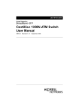
Front Panel Ports and LEDs
Figure 2-1. Front Panel Ports and Power LED
One RJ-45 Console Port
The RJ-45 labeled Console lets you connect a PC console to access the wireless
controller’s command-line interface.
Two Gigabit Option Ports
Two Gigabit Ethernet ports labeled Option let you connect the wireless controller to a
backbone (requires DWC-1000-VPN-LIC License Pack upgrade – see page 19). Each port
has an Activity LED (left) and Link LED (right) – see Table 2-1.
Table 2-1. Activity and Link LEDs
LED
Color
Description
Link LED
1000M
100M
Orange
ON = port is operating at 1000 Mbps (1 Gbps).
Green
ON = port is operating at 100 Mbps.
OFF = port is operating at 10 Mbps.
Activity LED
Green
ON = port link status is present.
Blink = port is sending or receiving data.
OFF = port has no link.
16
DWC-1000 Wireless Controller User’s Guide
Unpacking and Installation
Four Gigabit Ethernet LAN Ports
Four Gigabit Ethernet ports labeled LAN 1 through LAN 4 let you connect Ethernet devices
such as computers, switches, and hubs. Each port has an Activity LED (left) and Link LED
(right) – see Table 2-2.
Two USB 2.0 Ports
Two Universal Serial Bus (USB) 2.0 ports are provided for connecting USB flash drives, hard
drives, computers, and printers. Each port has an LED.
Table 2-2. USB LEDs
LED
USB LED
Color
Green
Description
ON = link is good.
Blink = there is activity on the port.
OFF = device is powered off.
Power LED
Facing the front of the wireless controller, the Power LED is located on the far left side. This
LED provides a visual indication of the wireless controller’s power-on or power-off state.
Table 2-3. Power LED
LED
Power LED
Color
Green
Description
ON = power-on process complete.
OFF= wireless controller is powered OFF.
Blink = system is defective and firmware upgrades have failed.
Orange
ON = power-on process in progress.
OFF= wireless controller is in recovery mode following a crash.
17
DWC-1000 Wireless Controller User’s Guide
Unpacking and Installation
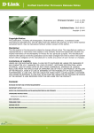
Rear Panel
Figure 2-2 and Table 2-4 describe the components on the rear panel of the wireless
controller.
Figure 2-2. Rear Panel Ports
Table 2-4. Rear Panel (Viewed from Right to Left)
Legend
Description
ON/OFF switch
AC socket
Reset button
Using the Reset Button
Using the reset button on the rear panel, you can perform a factory default reset. This
operation removes all overrides made to the wireless controller’s factory default
configuration and returns the wireless controller to its original factory default settings. To
protect against accidental resets, the reset button is recessed on the wireless controller’s
rear panel.
Note: You can also revert the wireless controller to its factory default settings from the
FIRMWARE page (see ―Restoring Factory Default Settings‖ on page 206).
To use the reset button to perform a factory default reset:
1. Leave power plugged into the wireless controller.
18
DWC-1000 Wireless Controller User’s Guide
Unpacking and Installation
2. Find the reset button on the back panel, and then use a thin object to press and hold the
reset button for at least 15 seconds.
3. Release the reset button.
Bottom Panel (Default IP Address)
The bottom of the wireless controller enclosure has a product label that shows the wireless
controller’s serial number, regulatory compliance, and other information.
Licenses
Two types of licenses are available for upgrading the wireless controller.
DWC-1000-AP6-LIC License Packs. Allow the wireless controller to manage 6 additional
access points. You can upgrade the wireless controller 3 times with these license packs,
enabling it to support a maximum of 24 access points.
DWC-1000-VPN-LIC License Pack. Allows the wireless controller to support VPN,
firewall, and routing functions via its two Gigabit Ethernet Option ports.
For more information about licenses, visit http://www.dlink.com and see ―Activating
Licenses‖ on page 211.
Installing the Wireless Controller
Rack-Mounting the Wireless Controller
The wireless controller can be mounted in a standard 19-inch equipment rack.
1. Attach the mounting brackets to each side of the chassis (see Figure 2-3) and secure them
with the supplied screws.
Figure 2-3. Attaching the Rack-Mount Brackets
19
DWC-1000 Wireless Controller User’s Guide
Unpacking and Installation
2. Use the screws provided with the equipment rack to mount the wireless controller in the
rack (see Figure 2-4).
Figure 2-4. Install the Wireless Controller in a Standard-Sized Equipment Rack
Connecting the Wireless Controller
To install the wireless controller, perform the following procedure (and see Figure 2-5 on
page 21).
1. Install the switch and access points according to the instructions in their documentation.
2. Connect one end of an Ethernet LAN cable to one of the ports labeled LAN (1-4) on the
front of the wireless controller. Connect the other end of the cable to an available RJ-45
port on the PoE switch in the LAN network segment.
3. Connect one of the wireless controller ports labeled LAN (1-4) to the network or directly to
a PC.
Your installation should resemble the one in Figure 2-5.
20
DWC-1000 Wireless Controller User’s Guide
Unpacking and Installation
Figure 2-5. Wireless Controller Installation
4. If you purchased a VPN/Firewall/Router License Pack, use the Option1 and Option2 ports
on the front of the wireless controller as follows:
–
Option1 = WAN port for connecting to a cable or DSL modem.
–
Option2 = WAN or DMZ port for dual WAN connections or internal server farm
purposes. If used as a DMZ port, the port’s IP address must be different than the IP
address of the wireless controller’s LAN interface.
5. Using the supplied power cord, connect the wireless controller to a working AC outlet.
6. Set the ON/OFF switch on the rear panel of the wireless controller to the ON position. The
green Power LED to the left of the front panel USB ports goes ON. If the LED is not ON,
see ―Power LED is OFF‖ on page 215.
21
DWC-1000 Wireless Controller User’s Guide
Unpacking and Installation
Sample Applications
The following sections describe three deployment scenarios to show how the wireless
controller can operate in a variety of network configurations.
Connecting to a Secured Network
Figure 2-6 shows a simple network with a wireless controller, Power over Ethernet (PoE)
switch, Layer 3 switch or router, and access points. This configuration allows you to send
data over the WLAN using Wired Equivalent Privacy (WEP) or Wi-Fi Protected Access
(WPA) to encrypt the data so that it becomes unreadable to outsiders.
In this configuration:
The access points and wireless controller are connected in the same subnet and use the
same IP address range assigned to that subnet.
There are no routers between the access points and the wireless controller.
The access points and wireless controller are connected to a PoE switch.
The uplink of the PoE switch provides Internet access.
The access points and wireless controller are configured for WEP or WPA.
The operating system on the computer that contains the network-interface card (NIC) is
configured with the same WEP or WPA network key settings configured on the switch and
wireless controller.
Figure 2-6. Example of Connecting to a Secured Network
22
DWC-1000 Wireless Controller User’s Guide
Unpacking and Installation
To configure the wireless controller for WPA or WPA/WPA2 security, perform the basic
configuration procedure described in Chapter 3, and then use the procedure below to
configure the wireless controller for WPA or WPA/WPA2 security.
Step
Configuration
1.
Under the SSID column, click an SSID.
2.
Change Wireless Network Configuration to desired settings,
including security.
3.
For Security, click None, WEP, or WPA/WPA2.
4.
If using WEP, enter a WEP key.
5.
If using WPA/WPA2, enter a WPA key.
6.
Click Save Settings.
Path in web Management Interface
ADVANCED > SSIDs
See
Page
36
Authenticating to an Authentication Server
Web authentication is a feature that denies a client access to the network until that client
supplies a valid username and password.
Figure 2-6 on page 22 shows an example of a network configuration that uses a wireless
controller, access points, PoE switch, and a Remote Authentication Dial In User Service
(RADIUS) for authentication. In this configuration, the RADIUS server authenticates users
before they gain access to the WLAN.
In this configuration:
The access points and wireless controller are connected in the same subnet and use the
same IP address range assigned to that subnet.
There are no routers between the access points and the wireless controller.
The access points and wireless controller are connected to a Power-over-Ethernet (PoE)
switch. The uplink of the PoE switch connects to a Layer 3 switch or router that provides
Internet access.
There is a shared secret key exchanged between the access point and RADIUS server.
User and user privileges are specified in the RADIUS database. (Servers using other
types of authentication, such as Kerberos, have other settings that must be configured.)
23
DWC-1000 Wireless Controller User’s Guide
Unpacking and Installation
To configure the wireless controller for this configuration, use the procedure below.
Step
Configuration
1.
Under the SSID column, click an SSID.
2.
Edit the SSID name, if necessary.
3.
Enter the RADIUS authentication server name.
4.
Optional: Enter the RADIUS accounting server name.
5.
Optional: Select a RADIUS use network configuration.
6.
Optional: Check RADIUS accounting.
7.
Optional: Enter a RADIUS authentication server name.
8.
Optional: Enter a RADIUS accounting server name.
9.
Click Save Settings.
Path in web Management Interface
ADVANCED > SSIDs
24
DWC-1000 Wireless Controller User’s Guide
See
Page
51
Unpacking and Installation
Logging In to a Captive Portal
The wireless controller lets you create a captive portal, which allows you to control which
web page is viewed when users first log onto a WLAN. Captive portals are used to control
Wi-Fi access at locations where users are ―captive,‖ such as hotels, apartments, business
centers, coffee houses, and restaurants.
A captive portal turns a user’s web browser into an authentication device by intercepting all
packets, regardless of address or port, when the user opens a browser and tries to access
the Internet. At that time, the browser is redirected to a web page that might require
authentication, payment, or user agreement to a use policy.
Figure 2-7 shows an example of a captive portal configuration with a wireless controller,
access points, PoE switch, and RADIUS authentication server.
In this configuration, you:
Create a group configured for captive portal users.
Add the captive portal users to the group and assign a password and idle timeout value to
it.
Select an interface for the captive portal.
Test your settings and make any necessary adjustments.
Figure 2-7. Example of a Captive Portal Configuration
25
DWC-1000 Wireless Controller User’s Guide
Unpacking and Installation
To configure an interface for captive portal access, perform the basic configuration
procedure described in Chapter 3, and then use the procedure below to configure an
interface for captive portal access. You can associate a configured captive portal with a
specific physical interface or wireless network (SSID).
Step
1.
Configuration
Create a captive portal.
Path in Web Management Interface
See
Page
ADVANCED > Users > Groups
43
ADVANCED > Users > Users
44
ADVANCE > Captive Portal > Wlan CP interface
association
47
ADVANCED > Captive Portal > Captive Portal Setup
48
ADVANCED > Captive Portal > Captive Portal Setup
50
a. Click Add.
b. Enter the name of a group and description.
c. Under User Type, check Captive Portal User.
d. Click Save Settings.
2.
Add captive portal users.
a. Click Add.
b. Enter a user name, first name, and last name.
c. Use Select Group to click the captive portal group
you created in step 1.
d. Enter a password.
e. Enter an idle timeout, in minutes.
f. Click Save Settings.
3.
Associate the captive portal group to an interface.
a. Select an interface in the Interface List.
b. Click Save Settings.
4.
a. Add a new Profile.
b. Configure the general details, header details, login
details, and footer details.
c. Click Save Settings.
5.
Test your settings.
a. Click a profile.
b. Click Show Preview.
Where to Go from Here
After installing the wireless controller, proceed to Chapter 3 to perform basic configuration
procedures.
26
DWC-1000 Wireless Controller User’s Guide
3. BASIC CONFIGURATION
After you install the wireless controller, perform the basic configuration instructions
described in this chapter. A basic configuration includes:
Logging In to the Web Management Interface (page 28)
Web Management Interface Layout (page 31)
Basic Configuration Procedures (page 32)
Using the information in this chapter, you can perform the basic information in minutes and
get your wireless controller up and running in a short period of time.
27
DWC-1000 Wireless Controller User’s Guide
Basic Configuration
Logging In to the Web Management Interface
Configuration procedures using the wireless controller’s web management interface are
performed using one of the following supported web browsers:
Browser
Version
Microsoft Internet Explorer
6.0 or higher
Mozilla Firefox
3.5 or higher
Netscape Navigator
9.0 or higher
Apple Safari
4.0
Google Chrome
5.0
Before you perform the following procedure:
Configure your PC running the web browser to use an IP address on the 192.168.10.0
network, with a subnet mask of 255.255.255.0.
Configure your web browser to accept cookies, prompt for pop-ups, and allow sites to run
JavaScript.
Upgrade the firmware for your wireless controller (see ―Upgrading Firmware‖ on page
208).
Upgrade the firmware for your access points after you upgrade the wireless controller
firmware (refer to the documentation for your access points). Firmware can be
downloaded from:
–
http://dlink.com/support/Wireless/dwl3600ap/Firmware/
–
http://dlink.com/support/Wireless/dwl6600ap/Firmware/
–
http://dlink.com/support/Wireless/dwl8600ap/Firmware/
To log in to the web management interface:
1. Launch a web browser on the PC.
2. In the address field of your web browser, type the IP address for the wireless controller
web management interface. Its default IP address is http://192.168.10.1. A login prompt
appears. If the login prompt does not appear, see ―Troubleshooting the Web Management
Interface‖ on page 216.
28
DWC-1000 Wireless Controller User’s Guide
Basic Configuration
3. If you are logging in for the first time, type the default case-sensitive user name admin and
the default case-sensitive password admin in lower-case letters.
Note: D-Link recommends that you change the password to a new, more secure
password (see ―Editing Users‖ on page 202) and record it in Appendix A.
4. Click Login. The web management interface opens, with the System Status page shown.
This page shows general, option, and LAN status information. You can return to this page
at any time by clicking STATUS > Device Info > System Status.
29
DWC-1000 Wireless Controller User’s Guide
Basic Configuration
5. To log out of the web management interface, click LOGOUT, which appears to the right of
the name of the currently displayed page.
30
DWC-1000 Wireless Controller User’s Guide
Basic Configuration
Web Management Interface Layout
A web management interface screen can include the following components (see Figure 3-1):
1st level: Main navigation menu tab. The main navigation menu tabs in the light gray bar
appear across the top of the web management interface. These tabs provide access to all
configuration menus and remain constant. The menu names appear in upper-case letters.
When you click a tab, the letters change to dark characters against a white background.
2nd level: Configuration menu tab. The configuration menu tabs appear at the left side of
the web management interface. These tabs change according to the main navigation
menu tab that you select. When you click a tab, the letters change to dark characters
against a white background.
3rd level: Submenu link. Some configuration menu tabs have one or more submenu links.
Some submenu links may have additional submenu links. A right arrow next to the menu
or submenu name indicates that there are submenu links. When you click one of these
menus or submenus, a list of submenu links appears. You can then click a submenu link
to display the configuration settings associated with it.
4th level: Workspace. The workspace shows the parameters associated with the selected
menu and submenu.
Action buttons. Action buttons change the configuration or allow you to make changes to
the configuration. Common action buttons are:
–
Save Settings. Saves all configuration changes made on the current screen. Saved
settings are retained when the wireless controller is powered off or rebooted, while
unsaved configuration changes are lost.
–
Don’t Save Settings. Resets options on the current screen to the last-applied or
last-saved settings.
–
Add. Adds a new item to the current screen.
–
Edit. Allows you to edit the configuration of the selected item.
–
Delete. Removes the selected item from the table or screen configuration.
Note: Below the Help menu on the main navigation tab is a Helpful Hints area that provides
online help for the page displayed in the workspace.
31
DWC-1000 Wireless Controller User’s Guide
Basic Configuration
Main Navigation
Menu Tab
Configuration
Menu Tab
Helpful
Hints
Workspace
Figure 3-1. Web Management Interface
Basic Configuration Procedures
To perform a basic configuration:
Basic Configuration Step #1. Enable DHCP Server (Optional) – see page 33.
Basic Configuration Step #2. Select the Access Points to be Managed – see page 34.
Basic Configuration Step #3. Change the SSID Name and Set Up Security – see page 36.
Basic Configuration Step #4. Confirm Access Point Profile is Associated – see page 42.
Basic Configuration Step #6. Use SSID with RADIUS – see page 51.
Basic Configuration Step #5. Configure Captive Portal Settings – see page 43.
32
DWC-1000 Wireless Controller User’s Guide
Basic Configuration
Basic Configuration Step #1. Enable DHCP Server (Optional)
By default, Dynamic Host Configuration Protocol (DHCP) is disabled in the wireless
controller. If you are not configuring your access points with static IP addresses, set up a
DHCP server or DHCP server relay on the network. If desired, perform the following
procedure to configure your wireless controller to act as a DHCP server.
1. Click SETUP > Network Settings > LAN Setup Configuration. The LAN SETUP page
appears.
2. Under LAN IP Address Setup, change the IP Address and Subnet Mask to values used
within your network. Record the settings below; you will refer to them later in this
procedure:
–
IP address: ___________________________________________
–
Subnet mask: _________________________________________
3. Click Save Settings.
4. Wait 60 seconds, and then start your web browser.
33
DWC-1000 Wireless Controller User’s Guide
Basic Configuration
5. In the web browser’s address field, enter the new IP address you recorded in step 2.
6. Click SETUP > Network Settings > LAN Setup Configuration.
7. In the LAN SETUP page, change DHCP Mode to DHCP Server.
8. Complete the fields in in the LAN SETUP page (see Table 3-1) and click Save Settings.
Table 3-1. DHCP Server Settings
Field
Description
DHCP
Starting IP Address
Enter the starting IP address in the IP address pool. Any new DHCP client joining the LAN is
assigned an IP address within the starting and ending IP address range. Starting and ending IP
addresses should be in the same IP address subnet as the wireless controller’s LAN IP address.
Ending IP Address
Enter the ending IP address in the IP address pool.
Default Gateway (Optional)
Enter the IP address of the gateway for your LAN.
Primary DNS Server
If configured domain name system (DNS) servers are available on the LAN, enter the IP address
of the primary DNS server.
Secondary DNS Server
If configured domain name system (DNS) servers are available on the LAN, enter the IP address
of the secondary DNS server.
Basic Configuration Step #2. Select the Access Points to be Managed
The wireless controller automatically discovers managed, unmanaged, and rogue access
points on the WLAN that are in the same IP subnet. Use the following procedure to select
the access points that the wireless controller will manage.
1. Click STATUS > Access Point Info > APs Summary. The ACCESS POINTS SUMMARY
page appears, with a list of the access points that the wireless controller has discovered.
34
DWC-1000 Wireless Controller User’s Guide
Basic Configuration
2. Under List of APs, check the first access point you want the wireless controller to manage,
click Manage, complete the fields in the VALID AP page (see Table 3-2), and click Save
Settings. When the confirmation appears, click OK.
3. Repeat step 2 for each additional access point you want the wireless controller to manage.
Table 3-2. Fields on the VALID AP Page
Field
Description
MAC Address
MAC address of the access point.
IP Address
Network address of the access point.
Age
Amount of time that has passed since the access point was last detected and the information
was last updated.
Status
Access point status. Possible values are:
Managed = access point profile configuration has been applied to the access point and the
access point operating in managed mode.
No Database Entry = access point’s MAC address does not appear in the local or RADIUS
Valid AP database.
Authentication (Failed AP) = access point failed to be authenticated by the wireless controller
or RADIUS server.
Failed = wireless controller lost contact with the access point. A failed entry will remain in the
Managed AP database unless you remove it. Note that a managed access point shows a
failed status temporarily during a reset.
Rogue = access point has not tried to contact the wireless controller and the access point’s
MAC address is not in the Valid AP database.
Radio
Wireless radio mode the access point is using.
35
DWC-1000 Wireless Controller User’s Guide
Basic Configuration
Field
Channel
Description
Operating channel for the radio.
Basic Configuration Step #3. Change the SSID Name and Set Up Security
You can configure up to 64 separate networks on the wireless controller and apply them
across multiple radio and virtual access point interfaces. By default, 16 networks are preconfigured and applied in order to the access points on each radio. In this procedure, you
will edit one of the preconfigured networks and change its SSID and security settings to suit
your requirements.
1. Click ADVANCED > SSIDs. The following NETWORKS page appears, with a list of the
wireless networks configured on the wireless controller.
2. Under the SSID column, click an SSID. The following NETWORKS page appears.
36
DWC-1000 Wireless Controller User’s Guide
Basic Configuration
3. Complete the fields on the NETWORKS page (see Table 3-3) and click Save Settings.
Table 3-3. SSID and Security Settings
Field
Description
SSID
Enter the case-sensitive name of the wireless network. Be sure the SSID is the same for all
devices in your wireless network.
Security
The default access point profile does not use any security mechanism. To protect your network,
we recommend you select a security mechanism to prevent unauthorized wireless clients from
gaining access to your network. Choices are:
None = no security mechanism is used.
WEP = enable WEP security. Complete the options in Table 3-4.
WPA/WPA2 = enable WPA/WPA2 security. Complete the options in Table 3-5.
37
DWC-1000 Wireless Controller User’s Guide
Basic Configuration
Table 3-4. WEP Page Settings
Field
Security
Description
If you select WEP for Security, the following two additional security options are displayed.
Static WEP = uses static key management. You manually configure the same keys to encrypt
data on both the wireless client and the access point. Dynamic WEP (WEP IEEE 802.1x) uses
dynamically generated keys to encrypt client-to- access point traffic.
WEP IEEE 802.1X = screen refreshes, and there are no more fields to configure. The access
point uses the global RADIUS server or the RADIUS server you specified for the wireless
network.
Authentication
Select the authentication type. Choices are:
Open System = any wireless station can request authentication. The station that needs to
authenticate with another wireless station sends an authentication management frame that
contains the identity of the sending station. The receiving station returns a frame that indicates
whether it recognizes the sending station.
Shared Key = each wireless station is assumed to have received a secret shared key over a
secure channel that is independent from the 802.11 wireless network communications
channel.
WEP Key Type
Select the key type. Choices are:
ASCII = upper- and lower-case alphabetic letters, numeric digits, and special symbols such as
@ and #.
HEX = digits 0 to 9 and letters A to F.
WEP Key Length (bits)
Select the length of the WEP key. Choices are:
64 = 64 bits
128 = 128 bits
Tx
Transfer Key Index. Indicates which WEP key the access point uses to encrypt the data it
transmits. To select a transfer key, click the button between the key number and the field where
you enter the key.
WEP Keys
You can specify four WEP keys. In each text box, enter a string of characters for each of the RC4
WEP keys shared with the stations using the access point. Use the same number of characters
for each key. The number of keys you enter depends on the WEP Key Type and WEP Key
Length selections. The following list shows the number of keys to enter in the field:
64 bit = ASCII: 5 characters; Hex: 10 characters
128 bit = ASCII: 13 characters; Hex: 26 characters
Each client station must be configured to use one of these WEP keys in the same slot as
specified here.
38
DWC-1000 Wireless Controller User’s Guide
Basic Configuration
Table 3-5. WPA/WPA/2 Page Settings
Field
Security
Description
If you select WPA for Security, the following two additional security options are displayed.
WPA/WPA2 Personal = uses static key management. You manually configure the same keys
to encrypt data on both the wireless client and the access point. WPA/WPA2 Enterprise uses a
RADIUS server and dynamically generated keys to encrypt client-to- access point traffic. WPA
Enterprise is more secure than WPA Personal, but you need a RADIUS server to manage the
keys.
WPA Enterprise = more secure than WPA Personal, but you need a RADIUS server to
manage the keys. If you click this option, the screen refreshes and the WPA Key Type and
WPA Key fields are hidden. The access point uses the global RADIUS server or the RADIUS
server you specified for the wireless network.
WPA Versions
Select the types of client stations you want to support. Choices are:
WPA = if all client stations on the network support the original WPA but none supports WPA2,
select WPA.
WPA2 = if all client stations on the network support WPA2, use WPA2, which provides the best
security per the IEEE 802.11i standard.
WPA and WPA2 = if you have a mix of clients that support WPA2 or WPA, select both boxes.
This lets both WPA and WPA2 client stations associate and authenticate, but uses the more
robust WPA2 for clients who support it. This WPA configuration allows more interoperability, at
the expense of some security.
WPA Ciphers
Select the cipher suite you want to use. Choices are:
TKIP
CCMP (AES)
TKIP and CCMP (AES)
Both TKIP and AES clients can associate with the access point. WPA clients must have a valid
TKIP key or AES-CCMP key to associate with the access point.
802.11n clients cannot use the TKIP cipher. If you enable TKIP only, 802.11 clients cannot
authenticate with the network.
WPA Key Type
Enter a WPA key type.
Range: ASCII, including upper- and lower-case alphabetic letters, numeric digits, and special
symbols such as @ and #
WPA Key
Enter the shared secret key for WPA Personal.
Range: 8 – 62 characters, including upper- and lower-case alphabetic letters, numeric digits, and
special symbols such as @ and #
Bcast Key Refresh Rate (seconds)
Enter a value to set the interval at which the broadcast (group) key is refreshed for clients
associated to this VAP.
Range: 0 - 86400 seconds (0 = broadcast key is not refreshed)
4. To add another SSID, repeat steps 1 through 3.
5. Click Advanced > AP Profile. The AP PROFILES SUMMARY page appears.
39
DWC-1000 Wireless Controller User’s Guide
Basic Configuration
6. Under Access Point Profile List, check the box to the left of the access point profile you
want to update.
7. Click Configure SSID. The AP PROFILES SUMMARY page appears.
40
DWC-1000 Wireless Controller User’s Guide
Basic Configuration
8. Click the radio button next to the Radio Mode you prefer.
9. Under List of SSID, check the box to the left of the SSID network you want to enable.
10. Click Save Settings.
41
DWC-1000 Wireless Controller User’s Guide
Basic Configuration
Basic Configuration Step #4. Confirm Access Point Profile is Associated
Use the following procedure to confirm that the access point profile is associated with the
wireless controller.
Tip: Each time you change configuration settings, perform this procedure to apply
the changes to the access point.
1. Click ADVANCED > AP Profile. The AP PROFILES SUMMARY page appears.
2. Under Access Point Profile List, check the box to the left of the access point profile you
want to update.
3. Click Apply.
4. Wait 30 seconds, and then click Refresh to verify that the profile is associated. Your
associated access point is configured and ready to authenticate wireless users.
42
DWC-1000 Wireless Controller User’s Guide
Basic Configuration
Basic Configuration Step #5. Configure Captive Portal Settings
Configuring the wireless controller’s captive portal settings is a 4-step process:
1. Create a captive portal group
a. Click ADVANCED > Users > Groups. The GROUPS page appears.
b. Click Add. The GROUP CONFIGURATION page appears.
43
DWC-1000 Wireless Controller User’s Guide
Basic Configuration
c. Complete the fields in Table 3-6 and click Save Settings.
Table 3-6. Captive Portal Settings
Field
Description
Group Configuration
Group Name
Enter a name for the group.
Description
Enter a description of the group.
User Type
Captive Portal User
Check this box.
2. Add captive portal users
a. Click ADVANCED > Users > Users. The USERS page appears.
44
DWC-1000 Wireless Controller User’s Guide
Basic Configuration
b. Click Add. The USERS CONFIGURATION page appears.
45
DWC-1000 Wireless Controller User’s Guide
Basic Configuration
c. Complete the fields in Table 3-7 and click Save Settings.
Table 3-7. Captive Portal User Settings
Field
Description
User Name
Enter a unique name for this user. The name should allow you to easily identify this user from
others you may add.
First Name
Enter the first name of the user. This is useful when the authentication domain is an external
server, such as RADIUS.
Last Name
Enter the last name of the user. This is useful when the authentication domain is an external
server, such as RADIUS.
Select Group
Select the captive portal group to which this user will belong.
Password
Enter a case-sensitive password that the user must specify before gaining access to the Internet.
For security, each typed password character is masked with a dot ().
Confirm Password
Enter the same case-sensitive password entered in the Password field. For security, each typed
password character is masked with a dot ().
Idle Timeout
Enter the number of minutes of inactivity that must occur before the user is logged out of his
session automatically. Entering an Idle Timeout value of 0 (zero) means never log out.
46
DWC-1000 Wireless Controller User’s Guide
Basic Configuration
3. Associate the captive portal group to an interface
a. Click ADVANCED > Captive Portal > Wlan CP Interface Association. The CAPTIVE
PORTAL page appears.
b. In the Interface List, click an interface.
Tip: Hold down the Shift key when clicking to select a contiguous range of
interfaces. To select non-contiguous interfaces hold down the Ctrl key and click
each interface. To deselect an interface, hold down Ctrl and click the highlighted
interface.
c. Click Add.
The captive portal is now associated to the selected interface. To test your configuration
from a client, connect to the captive portal SSID to log in to the captive portal. Enter an IP
address on the captive portal network to see the captive portal.
47
DWC-1000 Wireless Controller User’s Guide
Basic Configuration
4. Customize the captive portal login page
a. Click ADVANCED > Captive Portal > Captive Portal Setup. The CAPTIVE PORTAL
SETUP page appears.
b. Under List of Available Profiles, click Add to add a new profile or click the radio
button that corresponds to a profile name and click Edit to edit an existing profile. The
CUSTOMIZED CAPTIVE PORTAL SETUP page appears.
48
DWC-1000 Wireless Controller User’s Guide
Basic Configuration
c. Complete the fields (see Table 3-8) and click Save Settings. The message Operation
Succeeded appears and then the CAPTIVE PORTAL SETUP PAGE appears.
Table 3-8. Fields on the CUSTOMIZED CAPTIVE PORTAL SETUP Page
Field
Description
General Details
Profile Name
Enter a name for this captive portal profile. The name should allow you to differentiate this
captive profile from others you may set up.
Browser Title
Enter the text that will appear in the title of the browser during the captive portal session.
Page Background Color
Select the background color of the page that appears during the captive portal session.
49
DWC-1000 Wireless Controller User’s Guide
Basic Configuration
Field
Description
General Details
Custom Color (#)
Set the background color of the page that appears during the captive portal session.
Header Details
Background
Select whether the login page displayed during the captive portal session will show an image or
color. Choices are:
Image = show image on the page. Use the Header Background Color field to select a
background color. The maximum size of the image is 100 kb.
Color = show background color on the page. Use the radio buttons to select an image.
Header Background Color
If you set Background to Color, select a background color for the header.
Custom Color (#)
Use this field to customize the background color.
Header Caption
Enter the text that appears in the header of the login page during the captive portal session.
Caption Font
Select the font for the header text.
Font Size
Select the font size for the header text.
Font Color
Select the font color for the header text.
Login Details
Login Section Title
Enter the text that appears in the title of the login box when the user logs in to the captive portal
session. This field is optional.
Welcome Message
Enter the welcome message that appears when users log in to the captive session successfully.
This field is optional.
Error Message
Enter the error message that appears when users fail to log in to the captive session
successfully. This field is optional.
Footer Details
Change Footer Content
Enables or disables changes to the footer content on the login page. Choices are:
Checked – enable changes to the footer.
Unchecked – disable changes to the footer.
Footer Content
If Change Footer Content is checked, enter the text that appears in the footer.
Footer Font Color
If Change Footer Content is checked, select the color of the text that appears in the footer.
d. Under List of Available Profiles, click the profile and the Show Preview button for the
profile you just configured. Confirm that the appearance of the login page suits your
requirements. If not, repeat steps 5c through 5e as necessary.
e. When you are satisfied with the appearance of the custom portal page:
Under List of Available Profiles, click the profile and then click the Enable
button to enable the profile.
Under Captive Portal Policies, click a policy and then click the Enable button to
enable the policy.
50
DWC-1000 Wireless Controller User’s Guide
Basic Configuration
Basic Configuration Step #6. Use SSID with RADIUS
To use SSID with RADIUS authentication, perform the following procedure.
1. Click ADVANCED > SSIDs. The NETWORKS page appears.
2. Under the SSID column, click the SSID you want to edit.
3. At the next NETWORKS page, update the SSID name in the SSID field if needed.
4. Complete the fields in Table 3-3 and click Save Settings. Your access point is configured
to use RADIUS authentication server.
Table 3-9. RADIUS Settings
Field
RADIUS Authentication Server
Name
Description
Enter the name of the RADIUS server that the virtual access point uses for access point and
client authentication. Any RADIUS information you configure for the wireless network overrides
the global RADIUS information configured on the Wireless Global Configuration page. The
wireless controller acts as the RADIUS client and performs all RADIUS transactions on behalf of
the access points and wireless clients.
Range: 32 alpha-numeric characters, including spaces, underscores, and dashes
RADIUS Accounting Server Name
Enter the name of the RADIUS server that the virtual access point uses for reporting wireless
client associations and disassociations.
Range: 32 alpha-numeric characters, including spaces, underscores, and dashes
RADIUS Use Network
Configuration
Click Enable.
RADIUS Accounting
Click Enable.
Where to Go from Here
After installing the basic configuration procedures, the wireless controller is ready for
operation using the factory default settings in Appendix B. These settings should be suitable
for most users and most situations.
The wireless controller also provides advanced configuration settings for users who want to
take advantage of the more advanced features of the wireless controller. The following
sections list the wireless controller’s advanced settings. Users who do not understand these
features should not attempt to reconfigure their wireless controller, unless advised to do so
by the technical support staff.
For more information about advanced configuration settings, refer to the DWC-1000
Wireless Controller User Manual and the wireless controller Helpful Hints in the web
management interface (see ―Web Management Interface Layout‖ on page 31).
51
DWC-1000 Wireless Controller User’s Guide
4. ADVANCED CONFIGURATION SETTINGS
While the basic configuration described in the previous chapter is satisfactory for most
users, large wireless networks or a complex setup may require the wireless controller’s
advanced configuration settings to be configured.
This chapter covers the following commonly used advanced configuration settings.
QoS Configuration (page 53)
VLANs (page 59)
DMZ Settings (page 69)
Static Routing (page 72)
Auto-Failover Settings (page 76)
Load Balancing Settings (page 78)
For information about additional advanced configuration settings not described in this
chapter, see ―Additional Advanced Configuration ‖ on page 80.
Note: The procedures in this chapter should only be performed by expert users who
understand networking concepts and terminology.
52
DWC-1000 Wireless Controller User’s Guide
Advanced Configuration Settings
QoS Configuration
Configuring QoS settings is a 2-step process:
1. Enable QOS mode (see ―Enabling QoS Mode,‖ below), and
2. Define the DHCP or COS settings (see ―Defining DSCP and CoS Settings‖ on page 55).
Enabling QoS Mode
Path: SETUP > QoS > LAN QoS > Trust Mode Configuration
Using the LAN QOS page, you can enable Quality of Service (QoS) on the wireless
controller.
Typically, networks operate on a best-effort delivery basis, which means that all traffic has
equal priority and an equal chance of being delivered in a timely manner. When congestion
occurs, all traffic has an equal chance of being dropped.
When you configure the QoS feature, you can select specific network traffic, prioritize it
according to its relative importance, and use congestion-management and congestionavoidance techniques to provide preferential treatment. Implementing QoS in your network
makes network performance more predictable and bandwidth utilization more effective. It is
especially useful if you expect traffic congestion on the wireless controller LAN ports.
QoS classification can be applied in Layer 2 or Layer 3 frames. For this reason, you can
configure the wireless controller to use Layer 2 CoS settings or Layer 3 DSCP settings.
Note: The wireless controller also provides a CoS-to-DSCP map to map CoS values in
incoming packets to a DSCP value that QoS uses internally to represent the priority of the
traffic. To access this feature, click SETUP > QoS > Remark CoS to DSCP.
To configure QoS mode:
1. Click SETUP > QoS > LAN QoS > Trust Mode Configuration. The LAN QOS page
appears.
53
DWC-1000 Wireless Controller User’s Guide
Advanced Configuration Settings
2. Under LAN QoS, check Enable QoS for LAN ports. The fields under LAN QoS
configuration become available.
3. Under LAN QoS configuration, use the Classify Using drop-down list to select whether
DSCP or CoS will be used for the port.
4. Click Save Settings.
5. Proceed to ―Defining DSCP and CoS Settings‖ on page 55 to configure values for DSCP
and CoS and their priority.
54
DWC-1000 Wireless Controller User’s Guide
Advanced Configuration Settings
Defining DSCP and CoS Settings
After you enable QoS mode, use the procedures in the following sections to configure the
values and priorities used by DSCP and CoS.
Configuring DSCP Priorities
Path: SETUP > QoS > LAN QoS > IP DSCP Configuration
If you selected DSCP for your QoS configuration, use the following procedure to configure
and assign priority to the DSCP fields in IP packets.
1. Click SETUP > QoS > LAN QoS > IP DSCP Configuration. The PORT DSCP MAPPING
page appears. Each row corresponds to a DSCP field in an IP packet.
55
DWC-1000 Wireless Controller User’s Guide
Advanced Configuration Settings
2. On the appropriate row, use the Queue drop-down list to select one of the following
priorities:
–
Highest
–
Medium
–
Low
–
Lowest
3. Repeat step 2 for each additional DSCP field you want to prioritize.
4. When you finish, click Save Settings.
Configuring CoS Priorities
Path: SETUP > QoS > LAN QoS > 801.P Priority
If you selected CoS for your QoS configuration, use the following procedure to configure and
assign priority to the CoS fields in the IP packets.
1. Click SETUP > QoS > LAN QoS > 801.P Priority. The PORT COS MAPPING page
appears. Each row corresponds to a CoS field in an IP packet.
56
DWC-1000 Wireless Controller User’s Guide
Advanced Configuration Settings
2. On the appropriate row, use the Queue drop-down list to select one of the following
priorities:
–
Highest
–
Medium
–
Low
–
Lowest
3. Repeat step 2 for each additional CoS field you want to prioritize.
4. When you finish, click Save Settings.
57
DWC-1000 Wireless Controller User’s Guide
Advanced Configuration Settings
5. On the appropriate row, use the Queue drop-down list to select one of the following
priorities:
–
Highest
–
Medium
–
Low
–
Lowest
6. Repeat step 2 for each additional CoS field you want to prioritize.
7. When you finish, click Save Settings.
58
DWC-1000 Wireless Controller User’s Guide
Advanced Configuration Settings
VLANs
A virtual Local Area Network (VLAN) is a logical segment in a switched network. It allows
independent logical networks to be created within a single physical network. VLANs
separate devices into different broadcast domains and Layer 3 subnets. Devices within a
VLAN can communicate without routing. The primary use of VLANs is to split large switched
networks, which are large broadcast domains.
The wireless controller provides VLAN functionality for assigning unique VLAN IDs to LAN
ports so that traffic to and from that physical port can be isolated from the general LAN.
VLAN filtering is particularly useful to limit broadcast packets of a device in a large network.
Enabling VLANs
Path: SETUP > VLAN Settings > VLAN Configuration
By default, the wireless controller’s VLAN function is disabled. To enable it:
1. Click SETUP > VLAN Settings > VLAN Configuration. The VLAN CONFIGURATION
page appears.
2. Under VLAN Configuration, check Enable VLAN.
59
DWC-1000 Wireless Controller User’s Guide
Advanced Configuration Settings
3. Click Save Settings.
Creating VLANs
Path: SETUP > VLAN Settings > Available VLANs
After you enable the wireless controller’s VLAN function, use the AVAILABLE VLANS page
to create VLANs. After you create VLANs, you can use the same page to view, edit, and
delete VLANs.
To create a VLAN:
1. Click SETUP > VLAN Settings > Available VLANs. The AVAILABLE VLANs page
appears.
2. Click Add. The following page appears.
60
DWC-1000 Wireless Controller User’s Guide
Advanced Configuration Settings
3. Complete the fields in the page (see Table 4-1).
4. Click Save Settings.
Table 4-1. Fields on the AVAILABLE VLANS Page
Field
Description
Name
Enter a unique name for this VLAN. The name should allow you to easily identify this VLAN from
others you may add.
Id
Enter a unique ID to this VLAN. Range: 2 - 4093
Inter VLAN Routing Enable
Allows or denies communication between VLAN networks. Choices are:
Checked = allow communications between different VLANs.
Unchecked = deny communications between different VLANs.
61
DWC-1000 Wireless Controller User’s Guide
Advanced Configuration Settings
Editing VLANs
Path: SETUP > VLAN Settings > Available VLANs
After you add VLANs, there is only one setting you can change: inter-VLAN routing, which
allows or prevents communications between VLANs.
To edit a VLAN:
1. Click SETUP > VLAN Settings > Available VLANs. The AVAILABLE VLANs page
appears.
2. Under List of available VLANs, click the VLAN you want to edit and click Edit. The
following page appears.
62
DWC-1000 Wireless Controller User’s Guide
Advanced Configuration Settings
3. Change the Inter VLAN Routing Enable setting as desired (see Table 4-1 on page 61).
4. Click Save Settings.
63
DWC-1000 Wireless Controller User’s Guide
Advanced Configuration Settings
Deleting VLANs
Path: SETUP > VLAN Settings > Available VLANs
If you no longer need a VLAN, you can delete it.
Note: A precautionary message does not appear before you delete a VLAN. Therefore, be
sure you do not need a VLAN before you delete it.
To delete a VLAN:
1. Click SETUP > VLAN Settings > Available VLANs. The AVAILABLE VLANs page
appears.
2. Under List of available VLANs, click the VLAN you want to delete. (Or click the box next
to Name to select all VLANs.)
3. Click Delete. The selected VLAN is deleted.
64
DWC-1000 Wireless Controller User’s Guide
Advanced Configuration Settings
Port VLANs
Path: SETUP > VLAN Settings > Port VLAN
After you enable the wireless controller’s VLAN function, use the PORT VLANS page to
configure the ports participating in the VLAN.
1. Click SETUP > VLAN Settings > Port VLAN. The PORT VLAN page appears.
65
DWC-1000 Wireless Controller User’s Guide
Advanced Configuration Settings
MultiVLAN Subnets
Path: SETUP > VLAN Settings > Multiple VLAN Subnets
Each VLAN can be assigned a unique IP address and subnet mask for the virtually isolated
network. Unless you enabled inter-VLAN routing for the VLAN, the VLAN subnet determines
the network address on the LAN that can communicate with the devices that correspond to
the VLAN.
Using the MULTI VLAN SUBNETS page, you can view and edit the available multi-VLAN
subnets.
To view and edit the available multi-VLAN subnets:
1. Click SETUP > VLAN Settings > Multiple VLAN Subnets. The MULTI VLAN SUBNETS
page appears.
2. To edit a multi-subnet VLAN, check it and click Edit. The MULTI VLAN SUBNET CONFIG
page appears with the settings for the selected VLAN.
66
DWC-1000 Wireless Controller User’s Guide
Advanced Configuration Settings
3. Edit the settings as desired (see 67).
4. Click Save Settings.
Table 4-2. Fields on the MULTI VLAN SUBNET CONFIG Page
Field
Description
MULTI VLAN SUBNET
VLAN ID
Read-only field that shows the ID you assigned to the VLAN when you created it.
IP Address
Enter the IP address for the VLAN.
Subnet Mask
Enter the subnet mask for the VLAN.
DHCP
DHCP Mode
Select a DHCP mode for the VLAN. Choices are:
None = select this setting if the computers on the LAN are configured with static IP addresses
or are configured to use another DHCP server. The remaining fields become unavailable.
DHCP Server = select this setting to use the wireless controller as a DHCP server. Complete
the remaining settings on the page.
DHCP Relay = if you select this setting, you need only enter the relay gateway information.
Domain Name
Enter the domain name for the VLAN.
67
DWC-1000 Wireless Controller User’s Guide
Advanced Configuration Settings
Field
Description
MULTI VLAN SUBNET
Starting IP Address
Enter the starting IP address in the IP address pool. Any new DHCP client joining the LAN is
assigned an IP address within the starting and ending IP address range. Starting and ending IP
addresses should be in the same IP address subnet as the wireless controller’s LAN IP address.
Ending IP Address
Enter the ending IP address in the IP address pool.
Default Gateway (Optional)
Enter the IP address of the gateway for your LAN.
Primary DNS Server (Optional)
If configured domain name system (DNS) servers are available on the VLAN, enter the IP
address of the primary DNS server.
Secondary DNS Server (Optional)
If configured domain name system (DNS) servers are available on the VLAN, enter the IP
address of the secondary DNS server.
Lease Time
Enter a time interval, in hours, that a DHCP client can use the IP address that it receives from the
DHCP server. When the lease time is about to expire, the client sends a request to the DHCP
server to get a new lease.
Relay Gateway
Enter the gateway address. This is the only configuration parameter required in this section when
DHCP Mode = DHCP Relay.
LAN Proxy
Enable DNS Proxy
Enables or disables DNS proxy on this LAN. The feature is particularly useful in Auto Rollover
mode. For example, if the DNS servers for each connection are different, a link failure can render
the DNS servers inaccessible. However, when the DNS proxy is enabled, clients can make
requests to the wireless controller and the controller, in turn, sends those requests to the DNS
servers of the active connection. Choices are:
Checked = wireless controller acts as a proxy for all DNS requests and communicates with the
ISP's DNS servers (as configured in the Option settings page). All DHCP clients receive the
primary and secondary DNS IP addresses, along with the IP address where the DNS proxy is
running (i.e., the wireless controller's LAN IP).
Unchecked = all DHCP clients receive the DNS IP addresses of the ISP, excluding the DNS
proxy IP address.
68
DWC-1000 Wireless Controller User’s Guide
Advanced Configuration Settings
DMZ Settings
The wireless controller allows an Option port to be configured as a secondary Ethernet port
or dedicated Demilitarized Zone (DMZ) port. A DMZ allows one IP address (computer) to be
exposed to the Internet for activities such as Internet gaming and videoconferencing.
Configuring DMZ settings is a 2-step process:
1. Configure the wireless controller port to act as a DMZ (see ―Configuring a Port to Operate
as a DMZ,‖ below), and
2. Configure the DMZ settings for the port (see ―Configuring DMZ Settings‖ on page 70).
Configuring a Port to Operate as a DMZ
Path: SETUP > Internet Settings > Configurable Port
To configure a port to operate as a DMZ:
1. Click SETUP > Internet Settings > Configurable Port. The CONFIGURABLE PORT
page appears.
2. Under Configurable Port Status, click DMZ.
3. Click Save Settings.
69
DWC-1000 Wireless Controller User’s Guide
Advanced Configuration Settings
Configuring DMZ Settings
Path: SETUP > DMZ Setup > DMZ Setup Configuration
After you change the configurable port status to DMZ, use the following procedure to
configure DMZ settings.
Note: Your wireless controller may not display VPN-related menu options without the DWC1000-VPN-LIC License Pack (see ―Licenses‖ on page 19).
1. Click SETUP > DMZ Setup > DMZ Setup Configuration. The DMZ SETUP page
appears.
2. Complete the fields in the page (see Table 4-3).
3. Click Save Settings.
70
DWC-1000 Wireless Controller User’s Guide
Advanced Configuration Settings
Table 4-3. Fields on the DMZ SETUP Page
Field
Description
DMZ Port Setup
IP Address
Enter the IP address assigned to the wireless controller’s DMZ interface.
Subnet Mask
Enter the subnet mask assigned to the wireless controller’s DMZ interface.
DHCP for DMZ Connected Computers
DHCP Mode
Select a DHCP mode for the DMZ. Choices are:
None = select this setting if the computers on the DMZ are configured with static IP addresses
or are configured to use another DHCP server. The remaining fields become unavailable.
DHCP Server = select this setting to use the wireless controller as a DHCP server. Complete
the remaining settings on the page.
DHCP Relay = if you select this setting, you need only enter the relay gateway information.
Starting IP Address
Enter the first IP address in the range. Any new DHCP client joining the LAN will be assigned an
IP address between this address and the Ending IP Address. The Starting IP addresses should
be in the same network as the LAN TCP/IP address of the wireless controller.
Ending IP Address
Enter the last IP address in the range. Any new DHCP client joining the LAN will be assigned an
IP address between this address and the Ending IP Address. The Ending IP addresses should
be in the same network as the LAN TCP/IP address of the wireless controller.
Primary DNS Server
Enter the IP address of the primary DNS server.
Secondary DNS Server
Enter the IP address of a secondary DNS server.
WINS Server
(Optional) Windows Internet Naming Service (WINS) is equivalent to a DNS server, but uses the
NetBIOS protocol to resolve hostnames. If the network consists only of Windows-based
computers and you want to use a WINS server for name resolution, enter the IP address of the
WINS server. The router will include the WINS server IP address in the DHCP configuration
when acknowledging a DHCP request from a DHCP client.
Lease Time
Enter the duration, in hours, for which IP addresses will be leased to clients.
Relay Gateway
Enter the gateway address. This is the only configuration parameter required in this section when
DHCP Relay is selected as its DHCP mode.
DMZ Proxy
Enable DNS Proxy
Enables or disables DNS proxy on this LAN. Choices are:
Checked = enable DNS proxy on this LAN. The wireless controller acts as a proxy for all DNS
requests and communicates with the ISP's DNS servers (as configured in the Option settings
page). All DHCP clients receive the Primary/Secondary DNS IP along with the IP address,
where the DNS Proxy is running, i.e. the box's LAN IP. All DHCP clients receive the DNS IP
addresses of the ISP, excluding the DNS Proxy IP address when it is disabled. The feature is
useful in Auto Rollover mode. For example, if the DNS servers for each connection are
different, then a link failure may render the DNS servers inaccessible. However, when the
DNS proxy is enabled, then clients can make requests to the wireless controller and the
controller, in turn, sends those requests to the DNS servers of the active connection.
Unchecked = disable DNS proxy on this LAN.
71
DWC-1000 Wireless Controller User’s Guide
Advanced Configuration Settings
Static Routing
A static route tells network devices about an exact, fixed (hard-coded) destination. Static
routes can work well with small networks. Configuring your wireless controller for static
routing allows data transfers between it and a routing device without needing to use dynamic
routing protocols.
Adding a Static Route
Path: ADVANCED > Routing > Static Routing
To add a static route:
1. Click ADVANCED > Routing > Static Routing. The STATIC ROUTING page appears.
2. Click Add. The STATIC ROUTE CONFIGURATION page appears.
72
DWC-1000 Wireless Controller User’s Guide
Advanced Configuration Settings
3. Complete the fields in the page (see Table 4-4).
4. Click Save Settings.
Table 4-4. Fields on the STATIC ROUTE CONFIGURATION Page
Field
Description
Route Name
Enter a unique name for this static route. The name should allow you to easily identify this static
route from others you may add.
Active
Activates or deactivates the status route. Choices are:
Checked = activate static route.
Unchecked = deactivate static route.
Private
Designates the static route as private. Choices are:
Checked = static route is private.
Unchecked = static route is not private.
Destination IP Address
Enter the IP address of the static route’s destination.
IP Subnet Mask
Enter the subnet mask of the static route.
Interface
Select the wireless controller interface that will interface to the static route. Choices are:
Option = the wireless controller’s Option port will interface to the static route.
LAN > VLAN = the wireless controller’s LAN or VLAN port will interface to the static route.
Gateway IP Address
Enter the IP address of the gateway router, which is the next hop address for the wireless
controller.
Metric
Enter the administrative distance of the route.
73
DWC-1000 Wireless Controller User’s Guide
Advanced Configuration Settings
Editing Static Routes
Path: ADVANCED > Routing > Static Routing
After you add static routes, you can edit it if you need to change settings.
To edit a static route:
1. Click ADVANCED > Routing > Static Routing. The STATIC ROUTING page appears.
2. Under List of available static routes, click the static route you want to edit and click Edit.
3. Change the desired settings (see Table 4-4 on page 73).
4. Click Save Settings.
74
DWC-1000 Wireless Controller User’s Guide
Advanced Configuration Settings
Deleting Static Routes
Path: ADVANCED > Routing > Static Routing
If you no longer need a static route, you can delete it.
Note: A precautionary message does not appear before you delete a static route. Therefore,
be sure you do not need a static route before you delete it.
To delete a static route:
1. Click ADVANCED > Routing > Static Routing. The STATIC ROUTING page appears.
2. Under List of available Static Routes, click the static route you want to delete. (Or click
the box next to Name to select all static routes.)
3. Click Delete. The selected static route is deleted.
75
DWC-1000 Wireless Controller User’s Guide
Advanced Configuration Settings
Auto-Failover Settings
Path: SETUP > Internal Settings > Option Mode
You can configure two Option ports to form a redundancy group. You then designate one
Option port as the primary Internet link and the other as the secondary port. If the primary
port fails or is disconnected from the network, an automatic failover to the redundant port
occurs. The Option port then takes over all functions of the primary port.
The wireless controller supports auto-failover when:
A D-Link VPN license key has been installed (see ―Activating Licenses‖ on page 211).
Multiple Option ports are configured.
To configure the wireless controller for auto-failover:
1. Click SETUP > Internal Settings > Option Mode. The OPTION MODE page appears.
2. Under Port Mode, click Auto-Rollover using Option port. Then use the adjacent dropdown list to select the Option port that will be used as the failover port in case the primary
port encounters a problem
76
DWC-1000 Wireless Controller User’s Guide
Advanced Configuration Settings
3. Complete the settings under Option Failure Detection Method (see Table 4-5).
4. Click Save Settings.
Table 4-5. Option Failure Detection Method Fields
Field
Description
None
Wireless controller does not check for link failures.
DNS lookup using Option DNS
Servers
Detects failure of an Option link using the DNS servers configured in the Dedicated WAN or
Configurable Port WAN pages under the Networking menu.
DNS lookup using DNS Servers
Detects failure of an Option link using the DNS servers whose IP addresses you specify in the
Option 1 and Option 2 fields.
Option 1
If DNS lookup using DNS Servers is selected, enter the IP address of the first DNS server that
will check for link failures.
Option 2
If DNS lookup using DNS Servers is selected, enter the IP address of a second DNS server that
will check for link failures.
Ping these IP addresses
Detects Option failures by pinging the IP addresses you specify in the Option 1 and Option 2
fields.
Option 1
If Ping these IP addresses is selected, enter the first IP address to be pinged if a link failure
occurs.
Option 2
If Ping these IP addresses is selected, enter a second IP address to be pinged if a link failure
occurs.
Retry Interval is
Enter a number that tells the wireless controller how often, in seconds, to run the failure detection
method(s) configured above.
Failover after
Enter the number of retries the wireless controller attempts before initiating failover.
77
DWC-1000 Wireless Controller User’s Guide
Advanced Configuration Settings
Load Balancing Settings
Path: SETUP > Internal Settings > Option Mode
The wireless controller supports load balancing when:
A D-Link VPN license key has been installed (see ―Activating Licenses‖ on page 211).
Multiple Option ports are configured.
Protocol bindings have been configured (go to ADVANCED > Routing > Protocol
Bindings and refer to the online help).
Load balancing allows the wireless controller to distribute traffic among multiple Option
ports. The wireless controller supports the following types of load-balancing methods:
Round Robin – divides traffic equally among all Option ports. This selection is useful
when the connection speed of one Option port differs greatly from another. In this case
you can define protocol bindings to route low-latency services (such as VOIP) over the
higher-speed link and let low-volume background traffic (such as SMTP) go over the lower
speed link.
Spillover Mode – configures the Option port as a dedicated link until a user-defined load
tolerance or link bandwidth threshold is reached. If the link bandwidth exceeds the
threshold, the wireless controller directs the next connections to the secondary Option
port.
To configure the wireless controller for load balancing:
1. Click SETUP > Internal Settings > Option Mode. The OPTION MODE page appears.
78
DWC-1000 Wireless Controller User’s Guide
Advanced Configuration Settings
2. Under Port Mode, click Load Balancing. Then use the adjacent drop-down list to select
one of the following port balancing methods:
–
Round Robin – new connections to the Internet alternate between available links. If
you select this setting, complete the Option Failure Detection Method settings (see
Table 4-5 on page 77).
–
Spillover Mode – a single Option link is used for all connections until the bandwidth
threshold is reached, after which point the other Option link is used for new
connections. If you select this setting, complete the Option Failure Detection
Method settings (see Table 4-5) and SPILLOVER CONFIRMATION settings (see
Table 4-6).
3. Click Save Settings.
Table 4-6. SPILLOVER CONFIGURATION Fields
Field
Description
Load Tolerance
Enter the percentage of maximum bandwidth after which the wireless controller switches to the
secondary Option port.
Max Bandwidth
Enter the maximum bandwidth tolerable by the Primary Option. If the bandwidth falls below the
load tolerance value of configured Max Bandwidth, the wireless controller switches to the
secondary Option port.
79
DWC-1000 Wireless Controller User’s Guide
Advanced Configuration Settings
Additional Advanced Configuration Settings
The wireless controller provides more advanced configuration settings than covered in this
chapter. The following table describes these settings. For more information, go to the page
in the web management interface and then access the wireless controller online help in the
Helpful Hints area (see Figure 3-1 on page 32).
Note: Asterisks in the table below indicate advanced configuration settings that require a
DWC-1000-VPN-LIC License Pack.
Advanced Configuration Setting
Path
Advertisement prefixes
ADVANCED > IPv6 > IPv6 LAN > Advertisement Prefixes
Application rules*
ADVANCED > Application Rules > Application Rules
Application rules status*
ADVANCED > Application Rules > Application Rules Status
Auto VOIP
SETUP > QoS > LAN QoS > Auto VOIP
Configuration items
ADVANCED > Peer Controllers > Configuration Items
Configuration request status
ADVANCED > Peer Controllers > Configuration Request Status
Date and Time
TOOLS > Date and Time
DHCP v6 leased clients
ADVANCED > IPv6 > IPv6 LAN > DHCPv6 Leased Clients
Distributed tunneling
ADVANCED > Global > Distributed Tunneling
DMZ DHCP reserved leased clients
SETUP > DMZ Setup > DMZ DHCP Leased Clients
DMZ DHCP reserved IPs
SETUP > DMZ Setup > DMZ DHCP Reserved IPs
Double VLANs
SETUP > VLAN Settings > Double VLAN
Firmware via USB
TOOLS > Firmware via USB
Flow control
SETUP > QoS > LAN QoS > Flow Control
Get user database to the router
ADVANCED > Users > Get Users DB
GVRP
SETUP > GVRP
IGMP
ADVANCED > Advanced Network > IGMP Setup
IP aliasing*
SETUP > Internet Settings > IP Aliasing
IP/MAC binding
ADVANCED > IP/MAC Binding
IP mode
ADVANCED > IPv6 > IP Mode
IP option configuration
ADVANCED > IPv6 > IP Config
IP v6 LAN configuration
ADVANCED > IPv6 > IPv6 LAN > IPv6 LAN Config
IP v6 options*
ADVANCED > IPv6 > IPv6 LAN > IPv6 Option 1 Config
ADVANCED > IPv6 > IPv6 LAN > IPv6 Option 2 Config
80
DWC-1000 Wireless Controller User’s Guide
Advanced Configuration Settings
Advanced Configuration Setting
Path
LAN DHCP leased clients
SETUP > Network Settings > LAN DHCP Leased Clients
LAN DHCP reserved IPs
SETUP > Network Settings > LAN DHCP Reserved IPs
MAC-based VLANs
SETUP > VLAN Settings > MAC-based VLAN > MAC VLAN
Option mode*
SETUP > Internet Settings > Option Mode
Option port setup
SETUP > Option Port Settings > Option Setup
ADVANCED > Advanced Network > Option Port Setup*
Option port status
SETUP > Option Port Settings > Option Status
ADVANCED > Advanced Network > Option Port Setup*
Option QoS configuration
SETUP > QoS > LAN QoS > Policy based LAN QoS
OSPF
ADVANCED > Routing > OSPF
ADVANCED > IPv6 > OSPF
Peer controller configuration request status*
ADVANCED > Peer Controllers > Configuration Request Status
Peer controller configuration items*
ADVANCED > Peer Controllers > Configuration Items
Policy-based QoS
SETUP > Option Port Settings > Option Status
Port shaping
SETUP > QoS > LAN QoS > Port Shaping Rule
Protocol bindings
ADVANCED > Routing > Protocol Bindings
Protocol VLANs
SETUP > VLAN Settings > Protocol VLAN
Queue management
SETUP > QoS > LAN QoS > Queue Management
Queue scheduler
SETUP > QoS > LAN QoS > Queue Scheduler
Remark CoS to DSCP
SETUP > QoS > Remark CoS to DSCP.
Router advertisement
ADVANCED > IPv6 > IPv6 LAN > Router Advertisement
Routing mode*
SETUP > Internet Settings > Routing Mode
SNMP settings
TOOLS > Admin > SNMP
SNMP traps
ADVANCED > Global > SNMP Trap
Switch settings (including jumbo frames and power savings)
ADVANCED > Switch Settings
System check
TOOLS > System Check
Universal Plug and Play
ADVANCED > Advanced Network > UPnP
Voice VLANs
SETUP > VLAN Settings > MAC-based VLAN > Voice VLAN
WLAN global settings
SETUP > WLAN Global Settings
81
DWC-1000 Wireless Controller User’s Guide
5. SECURING YOUR NETWORK
The wireless controller supports a number of features for securing your network. This
chapter describes the following commonly used security features:
Managing Clients (page 83)
Content Filtering (page 88)
For information about additional security settings not described in this chapter, see
―Additional Security Settings‖ on page 94.
Note: The procedures in this chapter should only be performed by expert users who
understand networking concepts and terminology.
82
DWC-1000 Wireless Controller User’s Guide
Securing Your Network
Managing Clients
Using the KNOWN CLIENTS page, you can view wireless clients in the Known Client
database. The data base contains wireless client MAC addresses and names. The database
is used to retrieve descriptive client names from the RADIUS server and implement MAC
authentication.
The KNOWN CLIENTS page also lets you add, edit, and delete clients.
Viewing Known Clients and Adding Clients
Path: ADVANCED > Client
To view known clients:
1. Click ADVANCED > Client. The KNOWN CLIENTS page appears, with a list of the
wireless clients in the Known Client database.
83
DWC-1000 Wireless Controller User’s Guide
Securing Your Network
2. Click Add. The STATIC ROUTE CONFIGURATION page appears.
84
DWC-1000 Wireless Controller User’s Guide
Securing Your Network
3. Complete the fields in the page (see Table 5-1).
4. Click Save Settings.
Table 5-1. Fields on the KNOWN CLIENTS Page
Field
Description
MAC Address
Enter the MAC address for the known client.
Name
Enter the name of the known client. The name should allow you to differentiate this known client
from others you may add.
Authentication Action
If MAC authentication is enabled on the network, select the action to take on a wireless client.
Choices are:
Global Action = use the global white-list or black-list action configured on the Advanced Global
Configuration page to determine how to handle the client.
Grant = allow the client with the specified MAC address to access the network.
Deny = prohibit the client with the specified MAC address from accessing the network.
85
DWC-1000 Wireless Controller User’s Guide
Securing Your Network
Editing Clients
Path: ADVANCED > Client
After you add clients, you can edit it if you need to change settings.
To edit a client:
1. Click ADVANCED > Client. The KNOWN CLIENTS page appears.
2. Under List of Known Clients, click the client you want to edit and click Edit.
3. Change the desired settings (see Table 5-1 on page 85).
4. Click Save Settings.
86
DWC-1000 Wireless Controller User’s Guide
Securing Your Network
Deleting Clients
Path: ADVANCED > Client
If you no longer need a client, you can delete it.
Note: A precautionary message does not appear before you delete a client. Therefore, be
sure you do not need a client before you delete it.
To delete a client:
1. Click ADVANCED > Client. The KNOWN CLIENTS page appears.
2. Under List of Known Clients, click the client you want to delete. (Or click the box next to
List of Known Clients to select all clients.)
3. Click Delete. The selected client is deleted.
87
DWC-1000 Wireless Controller User’s Guide
Securing Your Network
Content Filtering
The wireless controller lets you control access to specific Web site addresses, URLs, and
keywords containing certain words or phrases. Using this feature, you can prevent
objectionable content from reaching your PCs.
Enabling Content Filtering
Path: ADVANCED > Website Filter > Content Filtering
By default, the wireless controller’s content-filtering function is disabled. Before you can
perform content-filtering tasks, enable the wireless controller’s content-filtering functions.
To enable content filtering:
1. Click ADVANCED > Website Filter > Content Filtering. The CONTENT FILTERING
page appears.
2. Under Content Filtering Configuration, check Enable Content Filtering. The fields
under Web Components become available.
88
DWC-1000 Wireless Controller User’s Guide
Securing Your Network
3. Under Web Components, check the Web components you want to subject to parental
controls.
4. Click Save Settings. Parental control settings are now enabled for the Web components
you selected. You can now use the procedures in this section to enforce parental controls.
Specifying Approved URLs
Path: ADVANCED > Website Filter > Approved URLs
With its content-filtering feature, the wireless controller prevents objectionable content from
reaching PCs by screening URLs. Using the APPPROVED URLS page, you can specify the
URLs that will not be blocked by parental controls. This page lets you create an acceptance
list for all URL domain names that are allowed in any form. For example, if you add Yahoo
to this list, examples of URLs that are permitted access from the LAN include
www.yahoo.com and yahooco.uk.
URLs can be entered individually or imported from comma-separated-value (CSV) files.
Note: The approved URLs you define here can be exported to a CSV file (see ―Exporting
Web Filters‖ on page 92).
To specify approved URLs:
1. Click ADVANCED > Website Filter > Approved URLs. The APPROVED URLS page
appears.
89
DWC-1000 Wireless Controller User’s Guide
Securing Your Network
2. To enter individual URLs, under Approved URLs List, click Add. When the APPROVED
URL CONFIGURATION page appears, enter an approved URL in the URL field and click
Save Settings. Repeat this step for each additional approved URL you want to add.
3. To import a CSV file of URLs, under Import Approved URLs, click Browse. In the
Choose File dialog box, find the file you want to import, click it, and click Open. Click
Import on the APPROVED URLs page and click Save Settings. Repeat this step for each
additional file of approved URLs you want to import.
4. To edit an approved URL, check the URL under Approved URLs List and click Edit.
When the APPROVED URL CONFIGURATION page appears, edit the URL in the URL
field and click Save Settings.
5. To delete an approved URL, check the URL under Approved URLs List and click Delete.
The URL is deleted without displaying a precautionary message.
90
DWC-1000 Wireless Controller User’s Guide
Securing Your Network
Specifying Blocked Keywords
Path: ADVANCED > Website Filter > Blocked Keywords
You can use the wireless controller to restrict access to Internet content based on keywords.
Up to 32 entries are supported. Keywords can be entered individually or imports from CSV
files.
Alternatively, you can configure the wireless controller to block all URLs.
Note: The blocked keywords you define here can be exported to a CSV file (see ―Exporting
Web Filters‖ on page 92).
To block all URLs or certain URLs based on keywords:
1. Click ADVANCED > Website Filter > Blocked Keywords. The BLOCKED KEYWORDS
page appears.
2. To block all URLs, under Blocked All URL Configuration, check Block All URLs.
91
DWC-1000 Wireless Controller User’s Guide
Securing Your Network
3. To enter individual keywords, click Add under Blocked Keywords. When the APPROVED
KEYWORD CONFIGURATION page appears, enter a keyword in the Blocked Keyword
field and click Save Settings. Repeat this step for each additional keyword you want to
add.
4. To import a CSV file of keywords, under Import Blocked Keywords, click Browse. In the
Choose File dialog box, find the file you want to import, click it, and click Open. Click
Import on the BLOCKED KEYWORDS page and click Save Settings. Repeat this step for
each additional file of blocked keywords you want to import
5. To edit a keyword, check the keyword under Blocked Keywords and click Edit. When the
APPROVED KEYWORD CONFIGURATION page appears, edit the keyword in the
Blocked Keyword field and click Save Settings.
6. To enable a keyword, check the keyword under Blocked Keywords and click Enable.
7. To disable a keyword, check the keyword under Blocked Keywords and click Disable.
8. To delete a keyword, check the keyword under Blocked Keywords and click Delete. The
keyword is deleted without displaying a precautionary message.
Exporting Web Filters
Path: ADVANCED > Website Filter > Export
Using the EXPORT WEB FILTER page, you can export the approved URLs and blocked
keywords you defined in the previous sections to a CSV file from which they can be
downloaded to a local host.
To enable Web filters:
1. Click ADVANCED > Website Filter > Export. The EXPORT WEB FILTER page appears.
92
DWC-1000 Wireless Controller User’s Guide
Securing Your Network
2. To export the approved URLs you defined under ―Specifying Approved URLs‖ on page 89,
under Export Web Filter, click the Export button next to Export Approved URLs. When
the File Download dialog box appears, click Save and save the file to a location.
3. To export the blocked keywords you defined under ―Specifying Blocked Keywords‖ on
page 91, under Export Web Filter, click the Export button next to Export Blocked
Keywords. When the File Download dialog box appears, click Save and save the file to a
location.
93
DWC-1000 Wireless Controller User’s Guide
Securing Your Network
Additional Security Settings
The wireless controller provides more security settings than those covered in this chapter.
The following table describes these settings. For more information, go to the page in the web
management interface and then access the wireless controller online help in the Helpful
Hints area (see Figure 3-1 on page 32).
Note: Asterisks in the table below indicate settings that require a DWC-1000-VPN-LIC
License Pack.
Security Setting
Path
Attack checks*
ADVANCED > Advanced Network > Attack Checks
Certificates
ADVANCED > Certificates
Firewall settings
ADVANCED > Firewall Settings
Default outbound policy
ADVANCED > Firewall Settings > Default Outbound Policy
Firewall rules
ADVANCED > Firewall Settings > Firewall Rules
Custom services
ADVANCED > Firewall Settings > Custom Services
ALGs
ADVANCED > Firewall Settings > ALGs
SMTP ALG
ADVANCED > Firewall Settings > SMTP ALG > SMTP ALG
Configuration
ADVANCED > Firewall Settings > SMTP ALG > Approved
Mail Ids
ADVANCED > Firewall Settings > SMTP ALG > Blocked Mail
Ids
ADVANCED > Firewall Settings > SMTP ALG > Subject list
Intel AMT*
ADVANCED > Intel AMT
RADIUS settings
ADVANCED > Radius Settings
USB device status
SETUP > USB Settings > USB Status
USB port sharing
SETUP > USB Settings > USB Share Port
94
DWC-1000 Wireless Controller User’s Guide
6. VPN SETTINGS
A Virtual Private Network (VPN) is a technology designed to increase the security of
information transferred over the Internet. A VPN creates a private encrypted tunnel from the
user's computer, through the local wireless network and Internet, all the way to the remote
endpoint, such as corporate servers and databases.
The wireless controller uses the Internet Protocol Security (IPSec) to secure IP traffic. IPSec
builds ―virtual tunnels‖ between a local and remote subnet for secure communication
between two networks. This connection is commonly known as a Virtual Private Network
(VPN).
Alternatively, tunneling protocols such as L2TP and PPTP can be used to achieve a secure
connection (such as to a corporate LAN) over the Internet. These tunneling protocols can
optionally be secured themselves using IPSec. The wireless controller supports a number of
features for securing your network.
This chapter describes the most commonly used VPN features:
Configuring VPN Clients (page 96)
Configuring IPsec Policies (page 98)
Mode Config Settings (page 112)
DHCP Range (page 115)
PPTP/LT2P Tunnels (page 116)
For information about additional VPN settings not described in this chapter, see ―Additional
VPN Settings‖ on page 126.
Note: The procedures in this chapter should only be performed by expert users who
understand networking concepts and terminology.
95
DWC-1000 Wireless Controller User’s Guide
VPN Settings
Configuring VPN Clients
The wireless controller supports the following types of tunnels:
Gateway-to-gateway VPN. This setup connects two or more wireless controllers to secure
traffic between remote sites. Figure 6-1 shows an example of this configuration.
Remote Client (client-to-gateway VPN tunnel). In this setup, the IP address of the remote
PC is not known. Therefore, the remote client initiates the VPN tunnel and the gateway
acts as a responder.
Remote client behind a NAT controller: In this setup, the client has a dynamic IP address
and is located behind a NAT controller. The remote PC client at the NAT controller initiates
a VPN tunnel, as the IP address of the remote NAT controller is not known in advance.
The gateway Option port acts as a responder.
Note: VPN client software is required to establish a VPN tunnel between the wireless
controller and remote endpoint. Open source software, such as OpenVPN or Openswan, as
well as Microsoft IPsec VPN software can be configured with the required IKE policy
parameters to establish an IPsec VPN tunnel. For more information, refer to the
documentation for the VPN client software.
Figure 6-1. Example of Gateway-to-Gateway IPsec VPN Tunnel
Using Two Wireless Controllers Connected to the Internet
96
DWC-1000 Wireless Controller User’s Guide
VPN Settings
Figure 6-2 shows an example of a configuration where three IPsec clients are connected to
an internal network through the wireless controller IPsec gateway.
Figure 6-2. Example of Three IPsec Client Connections to an Internal Network
through the Wireless Controller IPsec Gateway
97
DWC-1000 Wireless Controller User’s Guide
VPN Settings
Configuring IPsec Policies
IP Security (IPsec) is a suite of related protocols for cryptographically securing
communications at the IP Packet Layer. IPsec also provides methods for the manual and
automatic negotiation of security associations (SAs) and key distribution.
An IPsec tunnel consists of a pair of unidirectional SAs – one at each end of the tunnel –
that specify the security parameter index (SPI), destination IP address, and security
protocol.
IPsec routing policies allow you to specify the parameters for SAs between endpoints and
the wireless controller. You manage IPsec policies using the IPSEC POLICIES page.
Adding IPsec Policies
Path: SETUP > VPN Settings > IPsec > IPsec Policies
To add an IPsec policy:
1. Click SETUP > VPN Settings > IPsec > IPsec Policies. The IPSEC POLICIES page
appears.
2. Click Add. The IPSEC CONFIGURATION page appears.
98
DWC-1000 Wireless Controller User’s Guide
VPN Settings
3. Complete the fields in the page (see Table 6-1).
4. Click Save Settings.
Table 6-1. Fields on the IPSEC CONFIGURATION Page
Field
Description
General
Policy Name
Enter a unique name for this policy. The name should allow you to easily identify this policy from
others you may add.
Policy Type
Select a policy type. Choices are:
Auto Policy = some parameters for the VPN tunnel are generated automatically. This requires
using the Internet Key Exchange (IKE) protocol to perform negotiations between the two VPN
endpoints.
Manual Policy = all settings, including the keys, for the VPN tunnel are manually entered for
each end point. No third-party server or organization is involved.
IP Protocol Version
Select the Internet protocol version to be used. Choices are:
IPv4
IPv6
99
DWC-1000 Wireless Controller User’s Guide
VPN Settings
Field
IKE Version
Description
Select the IKE version to be used. Choices are:
IKEv1
IKEv2
IPsec Mode
Select the IPsec mode. Choices are:
Tunnel Mode = most commonly used between gateways, or at an end-station to a gateway,
the gateway acting as a proxy for the hosts behind it.
Transport Mode = used between end-stations or between an end-station and a gateway, if the
gateway is being treated as a host — for example, an encrypted Telnet session from a
workstation to a router, in which the wireless controller is the actual destination.
Select Local Gateway
If two Option ports are configured to connect to an ISP, select the gateway that will be used as
the local endpoint for this IPsec tunnel.
Remote Endpoint
Select the type of identifier that you want to provide for the gateway at the remote endpoint.
Choices are:
IP Address
FQDN
Enable Mode Config
Enables or disables the Mode Config feature. Mode Config is similar to DHCP and is used to
assign IP addresses to remote VPN clients, like iPhone VPN Client. Choices are:
Checked = enable Mode Config. If you enable Mode Config, configure the Mode Config
settings (see ―Mode Config Settings‖ on page 112).
Unchecked = disable Mode Config.
Enable NetBIOS
Determined whether NetBIOS broadcasts travel over the VPN tunnel. For client policies, the
NetBIOS feature is available by default. Choices are:
Checked = allows NetBIOS broadcasts to travel over the VPN tunnel
Unchecked = disables NetBIOS broadcasts over the VPN tunnel.
Enable RollOver
Determines whether the VPN will roll over when Option Mode is set to Auto Rollover on the
Option Mode page. Choices are:
Checked = allows the VPN to roll over when Option Mode is set to Auto Rollover on the Option
Mode page.
Unchecked = disables VPN rollover.
Protocol
Enable DHCP
Determines whether VPN clients obtain an assigned IP address using DHCP when they connect
to the wireless controller over IPsec. Choices are:
Checked = VPN clients get an IP address.
Unchecked = VPN clients do not get an IP address.
Tunnel mode IPsec policies require local and remote traffic settings to be defined. For both local and remote endpoints configure the
following settings.
100
DWC-1000 Wireless Controller User’s Guide
VPN Settings
Field
Local / Remote IP
Description
Select the type of identifier that you want to provide for the endpoint. Choices are:
Any = policy is for traffic from the given end point (local or remote). Note that selecting Any for
both local and remote end points is not valid.
Single = limits the policy to one host. Enter the IP address of the host that will be part of the
VPN in the Start IP Address field.
Range = allows computers within an IP address range to connect to the VPN. Enter the Start
IP Address and End IP Address in the provided fields.
Subnet = allows an entire subnet to connect to the VPN. Enter the network address in the
Start IP Address field and enter the Subnet Mask in the Subnet Mask field.
Local / Remote Start IP Address
Enter the first IP address in the range.
Local / Remote End IP Address
Enter the last IP address in the range. If Local / Remote IP = Single, leave the End IP Address
field blank.
Local / Remote Subnet Mask
If Local / Remote IP = Subnet, enter the Subnet Mask of the network. Do not use overlapping
subnets for remote or local traffic selectors. Otherwise, you must add static routes on the
wireless controller and the hosts to be used. Example of a combination to avoid is:
Local Traffic Selector = 192.168.75.0/24
Remote Traffic Selector = 192.168.0.0./16.
Local / Remote Prefix Length
If Local / Remote IP = Subnet and Protocol = IPv6, enter the prefix length of the network.
Enable Keepalive
Determined whether the wireless controller sends ping packets periodically to the host on the
peer side of the network to keep the tunnel alive. Choices are:
Checked = enables Keepalive.
Unchecked = disables Keepalive.
Source IP Address
If Enable Keepalive is checked, enter the IP address from which ping packet must be sent.
Destination IP Address
If Enable Keepalive is checked, enter the IP Address to which ping packet needs to be sent.
Detection Protocol
If Enable Keepalive is checked, specify how often the wireless controller sends ping packets.
Reconnect After Failure Count
If Enable Keepalive is checked, fresh negotiation starts when no acknowledgement is received
for the number of consecutive packets specified here.
Phase (IKE SA Parameters)
These settings are applicable for Auto IPsec policies that use IKE to perform negotiations between the two VPN endpoints.
Exchange Mode
IKE phase can occur in one of two exchange modes. Select an exchange mode. Choices are:
Main = negotiates the tunnel with higher security, but is slower than aggressive mode.
Aggressive = fewer exchanges are made and with fewer packets than main mode, allowing
this mode to establish a faster connection than main mode, but with lower security.
Direction / Type
Select a connection method. Choices are:
Initiator = wireless controller initiates the connection to the remote end.
Responder = wireless controller waits passively and responds to remote IKE requests.
Both = wireless controller work in either Initiator or Responder mode.
NAT Traversal
Enables or disables Network Address Translation (NAT) traversal. Choices are:
On = select this setting if you expect any NAT to occur during IPsec communication.
Off = select this setting if you do not expect NAT to occur during IPsec communication.
101
DWC-1000 Wireless Controller User’s Guide
VPN Settings
Field
Description
NAT Keep Alive Frequency
If NAT Traversal = On, use this option to control the keep-alive-frequency value. Keep-alive
packets are sent at the specified time interval and are used to keep the NAT mappings alive on
the NAT device. Setting this value to 0 disables this feature.
Local Identifier Type
Select the ISAKMP identifier for this router. Choices are:
Local WAN IP
FQDN
User-FQDN
DER ASN1 DN
Local Identifier
Enter the appropriate value for the local identifier.
If the Local or Remote Identifier is not an IP address, negotiation is only possible in aggressive
mode. If FQDN, User FQDN or DER ASN1 DN is selected, the wireless controller disables main
mode and sets the default setting to aggressive mode.
Remote Identifier Type
Select the ISAKMP identifier for this router. Choices are:
Remote WAN IP
FQDN
User-FQDN
DER ASN1 DN
Remote Identifier
Enter the appropriate value for the remote identifier.
If the Local or Remote Identifier is not an IP address, negotiation is only possible in aggressive
mode. If FQDN, User FQDN or DER ASN1 DN is selected, the wireless controller disables main
mode and sets the default setting to aggressive mode.
Encryption Algorithm
Check the algorithm used to negotiate the SA. Choices are:
DES = faster than 3DES, but less secure.
3DES = triple DES. More secure method than DES, but with lower throughput.
Advanced Encryption Standard is a block cipher that can be used at 128, 192, or 256 bits. The
higher the bit rate, the stronger the encryption but the trade-off is lower throughput. It is more
secure than DES or 3DES. The following AES choices are supported:
AES-128
AES-192
AES-256
BLOWFISH = a symmetric encryption algorithm that uses the same secret key to both encrypt
and decrypt messages. Blowfish is also a block cipher that divides a message into fixed length
blocks during encryption and decryption. Blowfish has a 64-bit block size and a key length of
anywhere from 32 bits to 448 bits, and uses 16 rounds of main algorithm.
CAST128 = a 128-bit block cipher. CAST is a strong, military-grade encryption algorithm that
has a solid reputation for its ability to withstand unauthorized access.
Authentication Algorithm
Specify the authentication algorithm for the VPN header. Ensure that the same authentication
algorithm is configured on both sides of the tunnel. Choices are:
MD5 = Message-Digest algorithm 5 (MD5). MD5 is less secure than SHA, but faster.
SHA-1 = Secure Hash Algorithm (SHA-1) hash function. SHA-1 uses a 160-bit encryption key
and is stronger than MD5.
SHA2-256 = SHA-256 hash function that uses 32-bit words.
SHA2-384 = SHA-384 hash function.
SHA2-512 = SHA-512 hash function that uses 64-bit words.
102
DWC-1000 Wireless Controller User’s Guide
VPN Settings
Field
Authentication Method
Description
Select an authentication method. Choices are:
Pre-Shared Key = simple password-based key.
RSA-Signature = disables the Pre-shared key field and uses the Active Self Certificate
uploaded in the Certificates page. A certificate must be configured in order for RSA-Signature
to work.
Pre-shared key
If Authentication Mode = Pre-Shared Key, enter an alpha-numeric key to be shared with IKE
peer. The key does not support double-quotation marks.
Diffie-Hellman (DH) Group
Determines whether the Diffie-Hellman algorithm is used when exchanging keys. The DH Group
sets the strength of the algorithm in bits. Ensure that the DH Group is configured identically on
both sides of the IKE policy.
SA-Lifetime
Enter the interval, in seconds, after which the Security Association becomes invalid.
Enable Dead Peer Detection
Determines whether dead peer detection is used to detect whether the Peer is alive or not.
Choices are:
Checked = enable dead peer detection. If a peer is detected as dead, it deletes the IPsec and
IKE Security Association.
Unchecked = disable dead peer detection.
Detection Period
Enter the interval between consecutive DPD R-U-THERE messages. DPD R-U-THERE
messages are sent only when the IPsec traffic is idle.
Reconnect after failure count
Enter the maximum number of DPD failures allowed before tearing down the connection.
Extended Authentication
Enables or disables Extended Authentication (XAUTH). Instead of configuring a unique VPN
policy for each user, you can enable the wireless controller to authenticate users from a stored
list of user accounts or with an external authentication server such as a RADIUS server. When
connecting many VPN clients to a VPN gateway router, XAUTH allows authentication of users
with methods in addition to the authentication method mentioned in the IKE SA parameters.
Choices are:
None = disable XAUTH.
IPsec Host = authentication performed by remote gateway. In the Username and Password
fields, enter the user name and password associated with the IKE policy for authenticating this
gateway by the remote gateway.
Edge Device = use this VPN firewall as a VPN concentrator, where one or more gateway
tunnels terminate. Enter the Authentication Type to be used in verifying credentials of the
remote VPN gateways.
Authentication Type
If Extended Authentication = Edge Device, select the type of authentication to be used. Choices
are:
User Database = verify against the wireless controller’s VPN user database. Users must be
added to the database.
Radius – PAP = VPN firewall checks the user database for user credentials. If the user
account is not present, the VPN firewall connects to the RADIUS server
Radius – CHAP = uses the challenge to hide the password.
Username
If Extended Authentication = IPsec Host, enter the user name associated with the IKE policy for
authenticating this gateway by the remote gateway.
Password
If Extended Authentication = IPsec Host, enter an alphanumeric password associated with the
IKE policy for authenticating this gateway by the remote gateway.
Phase 2 (Manual Policy Parameters)
This section is used when Policy Type = Manual under the General section of this page. The Manual Policy creates a Security
Association (SA) based on the following static inputs. For an example, see ―Example of a Manual Policy‖ on page 106.
103
DWC-1000 Wireless Controller User’s Guide
VPN Settings
Field
Description
SPI-Incoming
Enter a hexadecimal value from 3 and 8 characters. For example: 0x1234.
SPI-Outgoing
Enter a hexadecimal value from 3 and 8 characters. For example: 0x1234.
Encryption Algorithm
Select an algorithm to encrypt the data.
Key Length
If Encryption Algorithm = BLOWFISH or CAST12, enter a key length.
For BLOWFISH, the Key Length must be a value between 40 and 448, and a multiple of 8.
For CAST128, the Key Length must be a value between 40 and 128, and a multiple of 8.
Key-In
Enter the encryption key of the inbound policy. The length of the key depends on the algorithm
chosen:
DES = 8 characters
3DES = 24 characters
AES=128 = 16 characters
AES=192 = 24 characters
AES=256 = 32 characters
AES=CCM = 16 characters
AES=GCM = 20 characters
TWOFISH (128) = 16 characters
TWOFISH (192) = 24 characters
TWOFISH (256) = 32 characters
BLOWFISH and CAST128 are variable length algorithms
Key-Out
Enter the encryption key of the outbound policy. The length of the key depends on the algorithm
chosen, as shown for Key-In.
Integrity Algorithm
Select the algorithm used to verify the integrity of the data. Choices are:
SHA-1
SHA-224
SHA-256
SHA-384
SHA-512
MD5
Key-In
Enter the integrity key (for ESP with Integrity-mode) for the inbound policy. The length of the key
depends on the algorithm chosen:
MD5 = 16 characters
SHA=1 = 20 characters
SHA2=224 = 28 characters
SHA2=256 = 32 characters
SHA2=384 = 48 characters
SHA2=512 = 64 characters
Key-Out
Enter the integrity key (for ESP with Integrity-mode) for the outbound policy. The length of the
key depends on the algorithm chosen, as shown for Key-In.
Phase 2 (Auto Policy Parameters)
104
DWC-1000 Wireless Controller User’s Guide
VPN Settings
Field
Description
This section is used when Policy Type = Auto Policy under the General section of this page. These settings configure Phase 2
negotiations and should match the Phase 2 settings on the remote tunnel endpoint.
SA Lifetime
Enter the duration of the Security Association and select the unit (seconds or Kbytes) from the
drop-down list.
Seconds = measures the SA Lifetime in seconds. After the specified number of seconds
passes, the Security Association is renegotiated. Default value is 3600 seconds. Minimum
value is 300 seconds.
Kbytes = measures the SA Lifetime in kilobytes. After the specified number of kilobytes of data
is transferred, the SA is renegotiated. Minimum value is 1920000 KB.
When configuring a Lifetime in kilobytes (also known as lifebytes), two SAs are created for each
policy. One SA for inbound traffic and one for outbound traffic. Due to differences in the upstream
and downstream traffic flows, the SA may expire asymmetrically. For example, if the downstream
traffic is very high, the lifebyte for a download stream may expire frequently. The lifebyte of the
upload stream may not expire as frequently. Therefore, set the values reasonably to reduce the
difference in expiry frequencies of the SAs; otherwise, this asymmetry might exhaust system
resources. Lifebyte specifications are recommended for advanced users only.
Encryption Algorithm
Check the algorithm used to encrypt the data.
Integrity Algorithm
Check the algorithm used to verify the integrity of the data.
PFS Key Group
Enables or disables Perfect Forward Secrecy (PFS) to improve security. While slower, this
protocol helps to prevent eavesdroppers by ensuring that a Diffie-Hellman exchange is
performed for every phase-2 negotiation. Choices are:
Checked = enable PFS.
Unchecked = disable PFS.
105
DWC-1000 Wireless Controller User’s Guide
VPN Settings
Example of a Manual Policy
The following example shows settings on the IPSEC CONFIGURATION page for creating a
VPN tunnel between two routers:
Router 1: Option=10.0.0.1 LAN=192.168.10.1 Subnet=255.255.255.0
Policy Name: manualVPN
Policy Type: Manual Policy
Local Gateway: Option
Remote Endpoint: 10.0.0.2
Local IP: Subnet 192.168.10.0 255.255.255.0
Remote IP: Subnet 192.168.20.0 255.255.255.0
SPI-Incoming: 0x1111
Encryption Algorithm: DES
Key-In: 11112222
Key-Out: 33334444
SPI-Outgoing: 0x2222
Integrity Algorithm: MD5
Key-In: 1122334444332211
Key-Out: 5566778888776655
Router 2: Option=10.0.0.2 LAN=192.168.20.1 Subnet=255.255.255.0
Policy Name: manualVPN
Policy Type: Manual Policy
Local Gateway: Option
Remote Endpoint: 10.0.0.1
Local IP: Subnet 192.168.20.0 255.255.255.0
Remote IP: Subnet 192.168.20.0 255.255.255.0
SPI-Incoming: 0x2222
Encryption Algorithm: DES
Key-In: 33334444
Key-Out: 11112222
SPI-Outgoing: 0x1111
Integrity Algorithm: MD5
Key-In: 5566778888776655
Key-Out: 1122334444332211
106
DWC-1000 Wireless Controller User’s Guide
VPN Settings
Editing IPsec Policies
Path: SETUP > VPN Settings > IPsec > IPsec Policies
After you add IPsec policies, you may need to change their settings.
To edit an IPsec policy:
1. Click SETUP > VPN Settings > IPsec > IPsec Policies. The IPSEC POLICIES page
appears.
2. Under List of VPN Policies, check the IPsec auto policy or manual policy you want to edit
and click Edit. The IPSEC CONFIGURATION page appears.
3. Complete the fields in the page (see Table 6-1).
4. Click Save Settings.
107
DWC-1000 Wireless Controller User’s Guide
VPN Settings
Enabling IPsec Policies
Path: SETUP > VPN Settings > IPsec > IPsec Policies
To enable an IPsec policy:
1. Click SETUP > VPN Settings > IPsec > IPsec Policies. The IPSEC POLICIES page
appears.
2. Under List of VPN Policies, check the IPsec auto policy or manual policy you want to
enable and click Enable.
108
DWC-1000 Wireless Controller User’s Guide
VPN Settings
Disabling IPsec Policies
Path: SETUP > VPN Settings > IPsec > IPsec Policies
To disable an IPsec policy:
1. Click SETUP > VPN Settings > IPsec > IPsec Policies. The IPSEC POLICIES page
appears.
2. Under List of VPN Policies, check the IPsec auto policy or manual policy you want to
disable and click Disable.
109
DWC-1000 Wireless Controller User’s Guide
VPN Settings
Exporting IPsec Policies
Path: SETUP > VPN Settings > IPsec > IPsec Policies
You can export an IPsec policy to a local host.
To export an IPsec policy:
1. Click SETUP > VPN Settings > IPsec > IPsec Policies. The IPSEC POLICIES page
appears.
2. Under List of VPN Policies, check the IPsec auto policy or manual policy you want to
export and click Export. The VPN CONFIG EXPORT WIZARD FOR REMOTE DSR
appears.
3. Review and complete the settings as needed.
4. Click Export Policy at the bottom of the page to export the settings.
110
DWC-1000 Wireless Controller User’s Guide
VPN Settings
Deleting IPsec Policies
Path: SETUP > VPN Settings > IPsec > IPsec Policies
If you no longer need an IPsec policy, you can delete it.
Note: A precautionary message does not appear before you delete an IPsec policy.
Therefore, be sure you do not need an IPsec before you delete it.
1. Click SETUP > VPN Settings > IPsec > IPsec Policies. The IPSEC POLICIES page
appears.
2. Under List of VPN Policies, check the IPsec auto policy or manual policy you want to
delete and click Delete.
111
DWC-1000 Wireless Controller User’s Guide
VPN Settings
Mode Config Settings
Path: SETUP > VPN Settings > IPsec > IPsec Mode Config
If you enabled Mode Config settings on the IPSEC CONFIGURATION page, use the
following procedure to configure the Mode Config settings.
1. Click SETUP > VPN Settings > IPsec > IPsec Mode Config. The IPSEC MODE CONFIG
page appears.
2. Complete the fields in the page (see Table 6-2).
3. Click Save Settings.
4. To split DNS names, under Split DNS Names, click Add. In a split DNS infrastructure, you
create two zones for the same domain, one to be used by the internal network and the
other used by the external network. Split DNS directs internal hosts to an internal domain
name server for name resolution and external hosts are directed to an external domain
112
DWC-1000 Wireless Controller User’s Guide
VPN Settings
name server for name resolution.
When you click Add, the SPLIT DNS NAMES page appears. Enter a Domain Name in the
Domain Name field and click Save Settings.
The Split DNS Name section provides Edit and Delete buttons for changing or deleting
split DNS name configurations.
113
DWC-1000 Wireless Controller User’s Guide
VPN Settings
Table 6-2. Fields on the IPSEC MODE CONFIG Page
Field
Tunnel Mode
Description
Select a tunnel mode. Choices are:
Full Tunnel = every packet destined to the Internet or remote server goes through the tunnel.
Split Tunnel = traffic destined to the Internet does not pass through the tunnel.
Start IP Address
Enter the first address to be allocated in this pool.
End IP Address
Enter the last address to be allocated in this pool.
Primary DNS
Primary DNS server is used by clients connected to this router to resolve domain names. If
Tunnel Mode = Split Tunnel, the DNS server should be internal domain name server.
Secondary DNS
Secondary DNS Server is used by clients connected to this router to resolve domain names. If
Tunnel Mode = Split Tunnel, the DNS server should be internal domain name server.
Primary WINServer
Enter the primary Windows NetBIOS Name Server used by clients to resolve NetBIOS names.
Secondary WINServer
Enter the secondary Windows NetBIOS Name Server used by clients to resolve NetBIOS names.
Split DNS Names
In a split DNS infrastructure, you create two zones for the same domain, one to be used by the internal network and the other used by
the external network. Split DNS directs internal hosts to an internal domain name server for name resolution and external hosts are
directed to an external domain name server for name resolution.
114
DWC-1000 Wireless Controller User’s Guide
VPN Settings
DHCP Range
Path: SETUP > VPN Settings > IPsec > DHCP Range
If clients will connect to the IPsec VPN using DHCP, use the IP RANGE FOR DHCP OVER
IPSEC to configure the DHCP settings.
1. Click SETUP > VPN Settings > IPsec > SHCP Range. The IP RANGE FOR DHCP
OVER IPSEC page appears.
2. Complete the fields in the page (see Table 6-3).
3. Click Save Settings.
Table 6-3. Fields on the IP RANGE FOR DHCP OVER IPSEC Page
Field
Description
Starting IP Address
Enter the starting IP address to be allocated in this range.
Ending IP Address
Enter the last IP address to be allocated in this range.
Subnet Mask
Enter the subnet mask for the IP address range.
115
DWC-1000 Wireless Controller User’s Guide
VPN Settings
PPTP/LT2P Tunnels
The wireless controller supports VPN tunnels from either PPTP or L2TP ISP servers. In this
role, the wireless controller acts as a broker to allow the ISP's server to create a TCP control
connection between the LAN VPN client and the VPN server.
PPTP Tunnel Support
Configuring PPTP Clients
Path: SETUP > VPN Settings > PPTP > PPTP Client
PPTP VPN clients can be configured on the wireless controller. Using this client, you can
access a remote network that is local to the PPTP server. After client is enabled, you can
use the STATUS > Active VPNs page to establish a PPTP VPN tunnel.
To configure PPTP clients:
1. Click SETUP > VPN Settings > PPTP > PPTP Client. The PPTP CLIENT page appears.
2. Complete the fields in the page (see Table 6-4).
116
DWC-1000 Wireless Controller User’s Guide
VPN Settings
3. Click Save Settings.
Table 6-4. Fields on the PPTP CLIENT Page
Field
Description
PPTP Client Configuration
Enable PPTP Client
Enables or disables the PPTP client. Choices are:
Checked = enable PPTP client.
Unchecked = disable PPTP client.
PPTP Client Configuration
Server IP
Enter the IP address of the PPTP server.
Remote Network
Enter the network address of the remote network that is local to the PPTP server.
Remote Netmask
Enter the subnetmask of the remote network which is local to the PPTP server.
Username
Enter the username that the PPTP Client needs to connect to the PPTP server.
Password
Enter the password that the PPTP Client needs to connect to the PPTP server.
Mppe Encryption
Enables or disables the MPPE encryption client. MPPE is an encryption technology developed by
Microsoft to encrypt point-to-point links over a VPN tunnel. MPPE uses the RC4 algorithm with
either 40- or 128-bit keys. All keys are derived from the cleartext authentication password of the
user. RC4 is stream cipher; therefore, the sizes of the encrypted and decrypted frames are the
same size as the original frame. Choices are:
Checked = enable MPPE encryption.
Unchecked = disable MPPE encryption.
Idle Time Out
If there is no traffic from a user for more than the specified time-out, the connection is
disconnected.
Configuring PPTP Servers
117
DWC-1000 Wireless Controller User’s Guide
VPN Settings
Path: SETUP > VPN Settings > PPTP > PPTP Server
After you configure the PPTP clients for the PPTP VPN, use the following procedure to
configure the PPTP server. Once enabled, a PPTP server is available on the wireless
controller for LAN and Option PPTP client users to access. PPTP clients within range of
configured IP addresses of allowed clients can reach the wireless controller’s PPTP server.
After they are authenticated by the PPTP server (the tunnel endpoint), PPTP clients have
access to the network managed by the wireless controller.
To configure PPTP clients:
1. Click SETUP > VPN Settings > PPTP > PPTP Server. The PPTP SERVER page
appears.
2. Complete the fields in the page (see Table 6-5).
3. Click Save Settings.
118
DWC-1000 Wireless Controller User’s Guide
VPN Settings
Table 6-5. Fields on the PPTP SERVER Page
Field
Description
PPTP Client Configuration
Enable PPTP Server
Enables or disable the PPTP server. Choices are:
Checked = enable PPTP server.
Unchecked = disable PPTP server.
PPTP Routing Mode
Nat
NAT is a technique that allows several computers on a LAN to share an Internet connection. The
computers on the LAN use a "private" IP address range while the Option port on the router is
configured with a single "public" IP address. Along with connection sharing, NAT also hides
internal IP addresses from the computers on the Internet. Select NAT if your ISP has assigned
only one IP address to you. The computers that connect through the router will need to be
assigned IP addresses from a private subnet (for example:,192.168.10.0).
Classical
Enables or disables classical routing. Choices are:
Checked = enable classical routing. IP addresses on the LAN will be exposed and be in the
same subnet as the Option. If your ISP assigned an IP address for every computer you use,
select this option.
Unchecked = disable classical routing.
Enter the range of IP addresses that is allocated to PPTP Clients
Starting IP Address
Enter the starting IP address of the range of IP addresses to assign to connecting users. This IP
address is taken as the server IP address and rest of the addresses in the range are assigned to
clients.
Ending IP Address
Enter the ending IP address of the range of IP addresses to assign to connecting users.
Authentication Supported
PAP
Enables or disables support for Password Authentication Protocol (PAP) authentication method.
PAP is a 2-way handshake protocol designed for use with PPP. Password Authentication
Protocol is a plain text password used on older SLIP systems. It is not secure. Choices are:
Checked = enable support for PAP.
Unchecked = disable support for PAP.
CHAP
Enables or disables support for Challenge Handshake Authentication Protocol (CHAP)
authentication method. CHAP is a 3-way handshake protocol that is considered more secure
than PAP. Choices are:
Checked = enable support for CHAP.
Unchecked = disable support for CHAP.
MS-CHAP
Enables or disables support for MS-CHAP authentication method. MS-CHAP uses a Microsoft
version of RSA Message Digest 4 challenge-and-reply protocol. This only works on Microsoft
systems and enables data encryption. To select this authentication method causes all data to be
encrypted. Choices are:
Checked = enable support for MS-CHAP.
Unchecked = disable support for MS-CHAP.
119
DWC-1000 Wireless Controller User’s Guide
VPN Settings
Field
Description
PPTP Client Configuration
MS-CHAPv2
Enables or disables support for MS-CHAPv2 authentication method. Introduces an additional
feature not available with MSCHAP or standard CHAP authentication: the change password
feature. This feature lets the client change the account password if the RADIUS server reports
that the password has expired. Choices are:
Checked = enable support for MS-CHAPv2.
Unchecked = disable support for MS-CHAPv2.
Encryption Supported
Mppe 40 bit
Enables or disables MPPE 40-bit encryption (available only for MS-CHAP and MS-CHAPv2
authentication methods). Choices are:
Checked = enable MPPE 40-bit encryption.
Unchecked = disable MPPE 40-bit encryption.
Mppe 128 bit
Enables or disables MPPE 128-bit encryption (available only for MS-CHAP and MS-CHAPv2
authentication methods). Choices are:
Checked = enable MPPE 128-bit encryption.
Unchecked = disable MPPE 128-bit encryption.
Stateful Mppe
Enables or disables stateful MPPE encryption (available only for MS-CHAP and MS-CHAPv2
authentication methods). Stateful encryption provides the best performance, but may be
adversely affected by networks experiencing substantial packet loss. If you choose stateful
encryption, configure flow control (SETUP > QoS > LAN QoS > Flow Control ) to minimize the
detrimental effects of this lossiness. Choices are:
Checked = enable stateful MPPE encryption.
Unchecked = disable stateful MPPE encryption.
User Time-out
Idle TimeOut
If there is no traffic from a user for more than the specified time out, the connection is
disconnected. Entering an Idle TimeOut value of 0 (zero) means never log out.
120
DWC-1000 Wireless Controller User’s Guide
VPN Settings
L2TP Tunnel Support
Path: SETUP > VPN Settings > L2TP > L2TP Server
After you configure PPTP tunnel support, then configure L2TP tunnel support. Once
enabled, a L2TP server is available on the wireless controller for LAN and Option L2TP
client users to access. After the L2TP server is enabled, L2TP clients within the range of
configured IP addresses of allowed clients can reach the wireless controller’s L2TP server.
Once authenticated by the L2TP server (the tunnel endpoint), L2TP clients have access to
the network managed by the controller.
To configure L2TP tunnel support:
1. Click SETUP > VPN Settings > L2TP > L2TP Server. The L2TP SERVER page appears.
2. Complete the fields in the page (see Table 6-6).
3. Click Save Settings.
121
DWC-1000 Wireless Controller User’s Guide
VPN Settings
Table 6-6. Fields on the L2TP SERVER Page
Field
Description
L2TP Server Configuration
Enable L2TP Server
Enables or disable the L2TP server. Choices are:
Checked = enable L2TP server.
Unchecked = disable L2TP server.
L2TP Routing Mode
Nat
NAT is a technique that allows several computers on a LAN to share an Internet connection. The
computers on the LAN use a "private" IP address range while the Option port on the router is
configured with a single "public" IP address. Along with connection sharing, NAT also hides
internal IP addresses from the computers on the Internet. Select NAT if your ISP has assigned
only one IP address to you. The computers that connect through the router will need to be
assigned IP addresses from a private subnet (for example:,192.168.10.0).
Classical
Enables or disables classical routing. Choices are:
Checked = enable classical routing. IP addresses on the LAN will be exposed and be in the
same subnet as the Option. If your ISP assigned an IP address for every computer you use,
select this option.
Unchecked = disable classical routing.
Enter the range of IP addresses that is allocated to L2TP Clients
Starting IP Address
Enter the starting IP address of the range of IP addresses to assign to connecting users. This IP
address is taken as the server IP address and rest of the addresses in the range are assigned to
clients.
Ending IP Address
Enter the ending IP address of the range of IP addresses to assign to connecting users.
Authentication Supported
PAP
Enables or disables support for Password Authentication Protocol (PAP) authentication method.
PAP is a 2-way handshake protocol designed for use with PPP. Password Authentication
Protocol is a plain text password used on older SLIP systems. It is not secure. Choices are:
Checked = enable support for PAP.
Unchecked = disable support for PAP.
CHAP
Enables or disables support for Challenge Handshake Authentication Protocol (CHAP)
authentication method. CHAP is a 3-way handshake protocol that is considered more secure
than PAP. Choices are:
Checked = enable support for CHAP.
Unchecked = disable support for CHAP.
MS-CHAP
Enables or disables support for MS-CHAP authentication method. MS-CHAP uses a Microsoft
version of RSA Message Digest 4 challenge-and-reply protocol. This only works on Microsoft
systems and enables data encryption. To select this authentication method causes all data to be
encrypted. Choices are:
Checked = enable support for MS-CHAP.
Unchecked = disable support for MS-CHAP.
122
DWC-1000 Wireless Controller User’s Guide
VPN Settings
Field
Description
L2TP Server Configuration
MS-CHAPv2
Enables or disables support for MS-CHAPv2 authentication method. Introduces an additional
feature not available with MSCHAP or standard CHAP authentication, the change password
feature. This feature lets the client change the account password if the RADIUS server reports
that the password has expired. Choices are:
Checked = enable support for MS-CHAPv2.
Unchecked = disable support for MS-CHAPv2.
L2TP Secret Key
Enable L2TP Secret Key
Enables or disables the L2TP secret key. Choices are:
Checked = enable L2TP secret key.
Unchecked = disable L2TP secret key.
Secret Key
If Enable L2TP Secret Key = checked, enter the secret key required to make a L2TP connection.
User Time-out
Idle TimeOut
If there is no traffic from a user for more than the specified time out, the connection is
disconnected. Entering an Idle TimeOut value of 0 (zero) means never log out.
123
DWC-1000 Wireless Controller User’s Guide
VPN Settings
OpenVPN Support
Path: SETUP > VPN Settings > OpenVPN > Open VPN Configuration
An Open VPN session can be established through the wireless controller. OpenVPN allows
peers to authenticate each other using a pre-shared secret key, certificates, or
username/password. When used in a multiclient-server configuration, OpenVPN lets the
server release an authentication certificate for every client, using signature and Certificate
authority.
To configure OpenVPN support:
1. Click SETUP > VPN Settings > OpenVPN > Open VPN Configuration. The OPENVPN
CONFIGURATION page appears.
2. Complete the fields in the page (see Table 6-7).
3. Click Save Settings.
124
DWC-1000 Wireless Controller User’s Guide
VPN Settings
Table 6-7. Fields on the OPENVPN CONFIGURATION Page
Field
Description
OpenVPN Server/Client Configuration
Enable Openvpn
Enables or disables OpenVPN support. Choices are:
Checked = enable OpenVPN support.
Unchecked = disable OpenVPN support.
Mode
Select an OpenVPN daemon mode. Choices are:
Server = run OpenVPN daemon in server mode.
Client = run OpenVPN daemon in client mode.
Access Server Client = user must download the auto login profile from the OpenVPN Access
Server and upload the same to connect.
Server IP
If Mode = Client, enter the OpenVPN server IP address to which the client connects (Applicable
in client mode).
Vpn Network
Enter the IP address of the virtual network.
Vpn Netmask
Enter the netmask of the virtual network.
Port
Enter the port number on which OpenVPN server (or access server) runs.
Tunnel Protocol
Select the protocol used to communicate with the remote host. Choices are:
UDP
TCP
Encryption Algorithm
Select the cipher with which the packets are encrypted. Choices are:
BF-CBC
AES-128
AES-192
AES-256
Hash Algorithm
Select the message digest algorithm used to authenticate packets. Choices are:
SHA1
SHA256
SHA512
Tunnel Type
If Mode = Server, select the type of tunnel through which traffic is redirected. Choices are:
Full Tunnel = redirect all the traffic through the tunnel.
Split Tunnel = redirect traffic to only specified resources (added from openVpnClient Routes)
through the tunnel.
Enable Client to Client
Communication
Enables or disables OpenVPN clients to communicate with each other in split tunnel scenarios.
Choices are:
Checked = enable client-to-client communication.
Unchecked = disable client-to-client communication.
Updated Access Server-Client Configuration
Upload Status
Shows whether the user must download the auto-login profile and upload here to connect this
wireless controller to the OpenVPN access server.
File
Use this field and the Browse button to select the file containing the profile.
125
DWC-1000 Wireless Controller User’s Guide
VPN Settings
Certificates
Select the set of certificates OpenVPN server uses:
First Row = set of certificates and keys the server uses.
Second Row = set of newly uploaded certificates and keys.
Enable TLS Authentication Key
Enabling this option adds Transport Layer Security (TLS) authentication, which adds a layer of authentication. TLS uses public key
infrastructure (PKI) to acquire and validate digital certificates. A digital certificate is a cryptographically signed structure that guarantees
the association between at least one identifier and a public key. It is valid for a limited time period and use, subject to certificate policy
conditions. The Certificate Authority issues certificates to client and server. This option can only be checked if a TLS key is uploaded.
Additional VPN Settings
The wireless controller provides more VPN settings than those covered in this chapter. The
following table describes these settings. For more information, go to the page in the web
management interface and then access the wireless controller online help in the Helpful
Hints area (see Figure 3-1 on page 32).
Note: Asterisks in the table below indicate settings that require a DWC-1000-VPN-LIC
License Pack.
VPN Setting
L2TP active users
Path
SETUP > VPN Settings > L2TP > L2TP Active Users
OpenVPN
Local networking (split tunneling)
SETUP > VPN Settings > OpenVPN > OpenVPN Local Networks (Split
Remote networking (site to site)
SETUP > VPN Settings > OpenVPN > OpenVPN Remote Networks (Site To
OpenVPN authentication
SETUP > VPN Settings > OpenVPN > OpenVPN Authentication
PPTP active users
SETUP > VPN Settings > PPTP > PPTP Active Users
Tunneling)
Site)
SSL VPN client
SSL VPN client
SETUP > VPN Settings > SSL VPN Client > SSL VPN Client
Client routes
SETUP > VPN Settings > SSL VPN Client > Configured Client Routes
SSL VPN server
Enable SSL VPN server
SETUP > VPN Settings > SSL VPN Server > SSL VPN Server Enable
Login profiles
SETUP > VPN Settings > SSL VPN Server > Login Profiles
Portal layouts
SETUP > VPN Settings > SSL VPN Server > Portal Layouts
SSL VPN policies
SETUP > VPN Settings > SSL VPN Server > SSL VPN Policies
Resources
SETUP > VPN Settings > SSL VPN Server > Resources
Port forwarding
SETUP > VPN Settings > SSL VPN Server > Port Forwarding
126
DWC-1000 Wireless Controller User’s Guide
7. VIEWING STATUS AND STATISTICS
This chapter describes the following pages, which display wireless controller and access
point status information and statistics.
Path
Description
See
Page
STATUS > Dashboard > General
Shows CPU and memory utilization.
129
STATUS > Device Info > System Status
Summarizes the wireless controller configuration settings.
131
STATUS > Device Info > Wireless LAN AP Info
Shows details about the managed access points.
133
STATUS > Device Info > Cluster Information
Shows information about other wireless controllers in the network.
135
STATUS > Dashboard > Interface
Shows information about resources the system is using.
137
STATUS > Traffic Monitor > Device Statistics
Shows detailed transmit and receive statistics for each physical port.
139
STATUS > Traffic Monitor > Managed AP
Statistics
Shows information about traffic on the access point’s wired and wireless
interfaces.
140
STATUS > Traffic Monitor > Associated Clients
Statistics > WLAN Associated Clients
Tracks the traffic associated with the client connected to the wireless controller.
142
STATUS > Wireless Client Info > Associated
Clients > Status
Shows statistics about client traffic while the client is associated with a single
access point as well as throughout the roaming session.
144
STATUS > Active Sessions
Shows local and remote IP addresses, protocol used during the Internet sessions,
and state.
145
STATUS > Associated Clients > Status
Shows clients associated with the managed access points.
146
STATUS > LAN Clients Info > LAN Clients
Shows NetBios name (if available) and IP and MAC addresses of discovered LAN
hosts.
148
STATUS > LAN Clients Info > Detected Clients
Shows information about clients that have authenticated with an access point, and
clients that disassociate and are no longer connected to the system.
149
STATUS > Dashboard > Access Point
Shows summary information about managed, failed, and rogue access points the
wireless controller has discovered or detected.
151
STATUS > Access Points Info > APs Summary
Shows summary information about managed, failed, and rogue access points the
wireless controller has discovered or detected. Status entries can be deleted
manually.
153
Access Point Info > Managed AP Status
Shows a variety of information about each access point that the wireless
controller is managing.
155
Status > Access Point Info > Authentication
Failure Status
Shows information about access points that failed to establish communication
with the wireless controller.
157
127
DWC-1000 Wireless Controller User’s Guide
Viewing Status and Statistics
Path
Description
See
Page
Status > Access Point Info > AP RF Scan Status
Shows information about other access points and wireless clients that the
wireless controller has detected.
159
Path: STATUS > Global Info > Global Status
Shows status and statistics about the wireless controller and the objects
associated with it.
161
Status > Global Info > Peer Controller > Status
Shows information about other wireless controllers in the network.
164
Status > Global Info > Peer Controller >
Configuration
Shows information about the access points that each peer controller in the cluster
manages.
166
Status > Global Info > Peer Controller >
Managed AP
Shows information about the access points that each peer controller in the cluster
manages.
167
Status > Global Info > IP Discovery
Shows IP addresses of peer controllers and access points for the wireless
controller to discover and associate with as part of the WLAN.
169
Status > Global Info > Config Receive Status
Shows information about the configuration a controller receives from a peer.
171
Status > Global Info > AP H/W Capability
Shows information about radio hardware and IEEE mode supported by access
points, along with software images available for downloading to access points.
173
Status > Dashboard > Client
Shows information about all the clients connected through managed access
points.
174
Status > Wireless Client Info > Associated
Clients > Status
Shows a variety of information about the wireless clients that are associated with
the access points the wireless controller is managing.
176
STATUS > Wireless Client Info > Associated
Clients > SSID Status
Shows SSID information for the wireless clients on the WLAN.
178
STATUS > Wireless Client Info > Associated
Clients > VAP Status
Shows information about the virtual access points on the managed access point
that are associated wireless clients.
180
STATUS > Wireless Client Info > Associated
Clients > Controller Status
Shows information about the controller that manages the access point to which
the client is associated.
182
STATUS > Wireless Client Info > Detected
Clients
Shows information about clients that have authenticated with an access point and
clients that have disassociated and are no longer connected to the system.
184
STATUS > Wireless Client Info > Pre-Auth
History
Shows detected clients that have made pre-authentication requests and identifies
the access points that received the requests.
186
STATUS > Wireless Client Info > Roam History
Shows a client’s roaming history between access points.
187
128
DWC-1000 Wireless Controller User’s Guide
Viewing Status and Statistics
Viewing CPU and Memory Utilization
Path: STATUS > Dashboard > General
The wireless controller provides a dashboard that displays CPU and memory utilization. The
DASHBOARD page is organized into the following sections (see Table 7-1):
CPU Utilization – shows statistics for the wireless controller’s processor.
Memory Utilization – shows the system’s memory status.
Figure 7-1. DASHBOARD Page
129
DWC-1000 Wireless Controller User’s Guide
Viewing Status and Statistics
Table 7-1. Fields on the DASHBOARD Page
Field
Description
CPU Utilization
CPU usage by user
Percent of the CPU utilization currently consumed by all user space processes, such as SSL
VPN or management operations.
CPU usage by kernel
Percent of the CPU utilization currently consumed by kernel space processes, such as firewall
operations.
CPU idle
Percent of CPU cycles currently not in use.
CPU waiting for IO
Percent of CPU cycles allocated to input/output devices.
Memory Utilization
Total Memory
Total available volatile physical memory.
Used Memory
Memory used by all processes in the system.
Free Memory
Available free memory in the system.
Cached Memory
Cached memory in the system.
Buffer Memory
Buffered memory in the system.
130
DWC-1000 Wireless Controller User’s Guide
Viewing Status and Statistics
Viewing System Status
Path: STATUS > Device Info > System Status
The SYSTEM STATUS page summarizes the wireless controller configuration settings
configured in the Setup and Advanced menus. This page is organized into the following
sections:
General - shows system name, firmware and WLAN module version, and serial number.
Option Information and LAN Information – shows information based on the
administrator configuration parameters.
131
DWC-1000 Wireless Controller User’s Guide
Viewing Status and Statistics
Figure 7-2. SYSTEM STATUS Page
132
DWC-1000 Wireless Controller User’s Guide
Viewing Status and Statistics
Viewing Managed Access Point Information
Path: STATUS > Device Info > Wireless LAN AP Info
The WIRELESS LAN AP INFORMATION page shows details about the managed access
points (see Table 7-2). Checking a managed access point enables the buttons described in
Table 7-3.
Figure 7-3. WIRELESS LAN AP INFORMATION Page
133
DWC-1000 Wireless Controller User’s Guide
Viewing Status and Statistics
Table 7-2. Fields on the WIRELESS LAN AP INFORMATION Page
Field
Description
MAC Address (*) Peer Managed
Ethernet address of the managed access point. If an asterisk (*) follows the MAC address, the
access point is managed by a peer controller.
IP Address
Network IP address of the managed access point.
Age
Time since last communication occurred between the wireless controller and the access point.
Status
Current managed state of the access point. Possible values are:
Discovered = access point is discovered by the wireless controller, but not authenticated.
Authenticated = access point has been validated and authenticated (if authentication is
enabled), but it is not configured.
Managed = profile configuration has been applied to the access point and the access point is
operating in managed mode.
Failed = wireless controller lost contact with the access point. A failed entry remains in the
Managed AP database, unless you remove it. Note that a managed access point shows a
failed status temporarily during a reset.
If management connectivity is lost for a managed access point, both of its radios are turned down
and all clients associated with the access point are disassociated. The radios resume operation
when that access point is managed again by a wireless controller.
Profile
Configuration profile applied to the managed access point. The profile is assigned to the access
point in the Valid AP database.
Radio Interface
Wireless radio mode that each radio on the access point is using.
Table 7-3. Buttons on the WIRELESS LAN AP INFORMATION Page
Button
Description
View AP Details
Shows detailed status information collected from the access point.
View Radio Details
Shows detailed status for a radio interface.
View Neighbor APs
Shows the neighbor APs that the specified AP has discovered through periodic RF scans on the
selected radio interface.
View Neighbor Clients
Shows information about wireless clients associated with an access point or detected by the
access point radio.
View VAP Details
Shows summary information about the virtual access points (VAPs) for the selected access point
and the access point radio interface that the wireless controller manages.
View Distributed Tunnelling Details
Shows information about the L2 tunnels currently in use on the access point.
134
DWC-1000 Wireless Controller User’s Guide
Viewing Status and Statistics
Viewing Cluster Information
Path: STATUS > Device Info > Cluster Information
The CLUSTER INFORMATION page shows information about other wireless controllers in
the network. Peer wireless controllers within the same cluster exchange data about
themselves, their managed access points, and their clients. The wireless controller
maintains a database with this data, so you can view information about a peer, such as its IP
address and software version. If the wireless controller loses contact with a peer, all of the
data for that peer is deleted.
One wireless controller in a cluster is elected as a Cluster Controller. The Cluster Controller
collects status and statistics from the other controllers in the cluster, including information
about the access point’s peer controller and the clients associated to those access points.
Figure 7-4. CLUSTER INFORMATION Page
135
DWC-1000 Wireless Controller User’s Guide
Viewing Status and Statistics
Table 7-4. Fields on the CLUSTER Page
Field
Description
Cluster Information
Cluster Controller
Identifies whether the wireless controller is part of a cluster.
Yes = wireless controller is part of a cluster.
No = wireless controller is not part of a cluster.
Cluster Controller IP Address
IP address of the controller that controls the cluster.
Cluster Priority
Connected Peer Controllers
IP Address
IP address of the peer wireless controller in the cluster.
Vendor ID
Vendor ID of the peer controller software.
Software Version
Software version for the given peer controllers.
Protocol Version
Protocol version supported by the software on the peer wireless controllers.
Discovery Reason
Discovery method of the given peer wireless controller, either through an L2 Poll or IP Poll.
Managed AP Count
Number of access points that the wireless controller manages currently.
Age
Time since last communication with the wireless controller, in hours, minutes, and seconds.
136
DWC-1000 Wireless Controller User’s Guide
Viewing Status and Statistics
Viewing Hardware and Usage Statistics
Path: STATUS > Dashboard > Interface
The wireless controller provides a dashboard that displays information about the resources
the system is using.
Bandwidth usage and application usage are shown as graphs. A drop-down list lets you
filter the graphs to show all, LAN, or option interfaces.
Interface statistics for wired connections (LAN, Option1, Option 2/DMZ, and VLANs) show
information about packets through and packets dropped by the interface. Click refresh to
have this page retrieve the most current statistics (see Table 7-1):
137
DWC-1000 Wireless Controller User’s Guide
Viewing Status and Statistics
Figure 7-5. DASHBOARD Page
138
DWC-1000 Wireless Controller User’s Guide
Viewing Status and Statistics
Wired Port Statistics
Path: STATUS > Traffic Monitor > Device Statistics
The DEVICE STATISTICS page shows detailed transmit and receive statistics for each
physical port. This includes:
Port-specific packet-level information for each interface (Option1, Option 2/DMZ, LAN, and
VLANs)
Transmitted and received packets
Port collisions
Cumulating bytes/sec for transmit/receive directions for each interface
Port up time
If you suspect issues with any of the wired ports, use this table to identify uptime or transmit
level issues with the port. The statistics table has an auto-refresh control for displaying the
most current port level data at each page refresh. The default auto-refresh for this page is 10
seconds.
Figure 7-6. DEVICE STATISTICS Page
139
DWC-1000 Wireless Controller User’s Guide
Viewing Status and Statistics
Managed Access Points and Associated Clients Statistics
Path: STATUS > Traffic Monitor > Managed AP Statistics
The MANAGED AP STATISTICS page shows information about traffic on the access point’s
wired and wireless interfaces. This information can help diagnose network issues, such as
throughput problems.
Figure 7-7. MANAGED AP STATISTICS Page
Table 7-5. Fields on the MANAGED AP STATISTICS Page
Field
Description
MAC Address
MAC address of the client station.
Interface
Interface type (WLAN or Ethernet.).
Packets Transmitted
Number of packets transmitted to the client station.
Packets Received
Number of packets received by the client station.
Bytes Transmitted
Number of bytes transmitted to the client station.
Bytes Received
Number of bytes received by the client station.
140
DWC-1000 Wireless Controller User’s Guide
Viewing Status and Statistics
Table 7-6. Buttons on the MANAGED AP STATISTICS Information
Button
Description
View Details
Shows detailed status information collected from the access point
View Radio Details
Shows detailed status for a radio interface.
View VAP Details
Shows summary information about the virtual access points (VAPs) for the selected access point
and radio interface on the access points that the wireless controller manages.
View Distributed Tunneling Details
Shows information about access points that the client detects. The access point-access point
tunnelling mode is used to support L3 roaming for wireless clients without forwarding any data
traffic to the wireless controller.
Refresh
Updates the information shown on the page.
141
DWC-1000 Wireless Controller User’s Guide
Viewing Status and Statistics
LAN-Associated Clients
Path: STATUS > Traffic Monitor > Associated Clients Statistics > WLAN Associated
Clients
The ASSOCIATED CLIENTS STATISTICS page tracks the traffic associated with the client
connected to the wireless controller. A Refresh button lets you update the information
shown on the page. Checking a client and clicking the View Details button displays detailed
information about the selected client.
After clicking next to the MAC address, the View Details page shows the fields in Table 7-7.
This page shows information about the traffic a wireless client receives and transmits while it
is associated with a single access point. Use the menu above the table to view details about
an associated client. Each client is identified by its MAC address.
Figure 7-8. ASSOCIATED CLIENTS STATISTICS Page
142
DWC-1000 Wireless Controller User’s Guide
Viewing Status and Statistics
Table 7-7. Fields on the ASSOCIATED CLIENTS STATISTICS Page
Field
Description
Packets Received
Total number of packets received from the client station.
Bytes Received
Total number of bytes received from the client station.
Packets Transmitted
Total number of packets transmitted to the client station.
Bytes Transmitted
Total number of bytes transmitted to the client station.
Packets Receive Dropped
Number of packets received from the client station that were dropped.
Bytes Receive Dropped
Number of bytes received from the client station that were dropped.
Packets Transmit Dropped
Number of packets transmitted to the client station that were dropped.
Bytes Transmit Dropped
Number of bytes transmitted to the client station that were dropped.
Fragments Received
Total number of fragmented packets received from the client station.
Fragments Transmitted
Total number of fragmented packets transmitted to the client station.
Transmit Retries
Number of times transmits to client station succeeded after one or more retries.
Transmit Retries Failed
Number of times transmits to client station failed after one or more retries.
TS Violate Packets Received
Count of packets received by an access point from a wireless client for the specified access
category.
TS Violate Packets Transmitted
Count of packets transmitted by an access point to a wireless client for the specified access
category.
Duplicates Received
Total number of duplicate packets received from the client station.
Table 7-8. Buttons on the ASSOCIATED CLIENTS STATISTICS Page
Field
Description
Refresh
Updates the information shown on the page.
View Details
Shows detailed status associated client.
143
DWC-1000 Wireless Controller User’s Guide
Viewing Status and Statistics
WLAN-Associated Clients
Path: STATUS > Wireless Client Info > Associated Clients > Status
The wireless client can roam among access points without interruption in WLAN service.
The wireless controller tracks the traffic the client sends and receives during the entire
wireless session while the client roams among access points being managed by the wireless
controller.
Using the ASSOCIATED CLIENTS STATUS page, you can view statistics stored by the
wireless controller about client traffic while the client is associated with a single access point
as well as throughout the roaming session.
Figure 7-9. ASSOCIATED CLIENTS STATISTICS Page
Table 7-9. Fields on the ASSOCIATED CLIENTS STATISTICS Page
Field
Description
MAC Address
MAC address of the client station.
Packets Transmitted
Number of packets transmitted to the client station.
Packet Received
Number of packets received by the client station.
144
DWC-1000 Wireless Controller User’s Guide
Viewing Status and Statistics
Field
Description
Bytes Transmitted
Number of bytes transmitted to the client station.
Bytes Received
Number of bytes received by the client station.
Sessions through the Wireless Controller
Path: STATUS > Active Sessions
The ACTIVE SESSIONS page shows the following information about the active Internet
sessions through the wireless controller:
Local and remote IP addresses
Protocol used during the Internet sessions
State
Figure 7-10. ACTIVE SESSIONS Page
145
DWC-1000 Wireless Controller User’s Guide
Viewing Status and Statistics
Associated Clients
Path: STATUS > Associated Clients > Status
The ASSOCIATED CLIENTS STATUS page shows clients that are associated with the
access points being managed by the wireless controller.
Figure 7-11. ASSOCIATED CLIENTS STATUS Page
Table 7-10. Fields on the ASSOCIATED CLIENTS STATUS Page
Field
Description
MAC Address
Ethernet address of the client station. If the MAC address is followed by an asterisk (*), the client
is associated with an access point managed by a peer controller.
AP MAC Address
Ethernet address of the access point.
SSID
Name of the network on which the client is connected.
BSSID
Ethernet MAC address for the managed access point/virtual access point where this client is
associated.
Detected IP Address
IPv4 address of the client, if available.
146
DWC-1000 Wireless Controller User’s Guide
Viewing Status and Statistics
Field
Status
Description
Indicates whether the client is associated and/or authenticated. The valid values are:
Associated = client is currently associated to the managed access point.
Authenticated = client is currently associated and authenticated to the managed access point.
Disassociated = client has disassociated from the managed access point. If the client does not
roam to another managed access point within the client roam timeout, it is deleted.
Table 7-11. Buttons on the ASSOCIATED CLIENTS STATUS Page
Button
Description
Disassociate
Disassociates the client from the managed access point.
View Details
For each client associated with an access point that the wireless controller manages, you can
view detailed status information about the client and its association with the access point.
View Neighbor Status
Shows information about access points that the client detects. The information on this page can
help you determine the managed access point an associated client might use for roaming.
View Distributed Tunneling Status
Shows information about access points that the client detects. The tunnelling mode is used to
support L3 roaming for wireless clients without forwarding any data traffic to the wireless
controller.
View SSID Details
Each managed access point can be from different networks that each have a unique SSID.
Although several wireless clients might be connected to the same physical AP, they might not
connect by using the same SSID. The WLAN > Monitoring > Client > Associated Clients >
SSID Status page lists the SSIDs of the networks that each wireless client associated with a
managed access point has used for WLAN access.
View VAP Details
Each access point has a set of Virtual Access Points (VAPs) per radio, and every VAP has a
unique MAC address (BSSID). This displays the VAP Associated Client Status page, which
shows information about the VAPs on the managed AP that have associated wireless clients.
147
DWC-1000 Wireless Controller User’s Guide
Viewing Status and Statistics
LAN Clients
Path: STATUS > LAN Clients Info > LAN Clients
LAN clients to the wireless controller are identified by an address resolution protocol (ARP)
scan through the LAN controller. The LAN CLIENTS page shows the:
NetBios name (if available)
IP address of discovered LAN hosts
MAC address of discovered LAN hosts
Figure 7-12. LAN CLIENTS Page
148
DWC-1000 Wireless Controller User’s Guide
Viewing Status and Statistics
Detected Clients
Path: STATUS > LAN Clients Info > Detected Clients
Wireless clients are detected by the wireless system either when the clients attempt to
interact with the system or when the system detects traffic from the clients. The Detected
Client Status page shows information about clients that have authenticated with an access
point as well information about clients that disassociate and are no longer connected to the
system.
Figure 7-13. DETECTED CLIENT STATUS Page
149
DWC-1000 Wireless Controller User’s Guide
Viewing Status and Statistics
Table 7-12. Fields on the DETECTED CLIENT STATUS Page
Field
Description
MAC Address
Ethernet MAC address of the client.
Client Name
Name of the client, if available, from the Known Client Database. If the client is not in the
database, the field is blank.
Client Status
Client status, which can be one of the following values:
Authenticated = wireless client is authenticated with the wireless system.
Detected = wireless client is detected by the wireless system, but is not a security threat.
Black-Listed = client with this MAC address is specifically denied access via MAC
authentication.
Rogue = client is classified as a threat by one of the threat-detection algorithms.
Age
Time since any event has been received for this client that updated the detected client database
entry.
Create Time
Time since this entry was first added to the detected client database.
150
DWC-1000 Wireless Controller User’s Guide
Viewing Status and Statistics
Access Point Status
Path: STATUS > Dashboard > Access Point
The ACCESS POINT page shows summary information about managed, failed, and rogue
access points the wireless controller has discovered or detected. A pie chart at the bottom of
the page provides a graphical representation of the total access point utilization.
Figure 7-14. ACCESS POINT Page
151
DWC-1000 Wireless Controller User’s Guide
Viewing Status and Statistics
Table 7-13. Fields on the ACCESS POINT Page
Field
Description
Total Access Points Utilization - Data
Total Access Points
Total number of managed access points in the database. This value equals the sum of Managed
Access Points, Connection Failed Access Points, and Discovered Access Points.
Managed Access Points
Number of access points in the Managed AP database that are authenticated, configured, and
have an active connection with the controller.
Discovered Access Points
Access points that have a connection with the controller, but have not been configured
completely. This value includes all managed access points with a Discovered or Authenticated
status.
Connection Failed Access Points
Number of access points that were previously authenticated and managed, but currently don't
have connection with the wireless controller.
Access Points Utilization
Standalone Access Points
Number of trusted access points in Standalone mode. Access points in Standalone mode are not
managed by a wireless controller.
Rogue Access Points
Number of rogue access points currently detected on the WLAN. When an access point performs
an RF scan and detects access points that have not been validated, it reports them as rogues.
Authentication Failed Access
Points
Number of access points that failed to establish communication with the controller.
Unknown Access Points
Number of Unknown access points currently detected on the WLAN. If an access point
configured to be managed by the controller is detected through an RF scan at any time that it is
not actively managed it is classified as an Unknown access point.
Rogue access point Mitigation
Limit
Maximum number of access points for which the system can send de-authentication frames.
Rogue access point Mitigation
Count
Number of access points to which the wireless system is currently sending de-authentication
messages to mitigate against rogue access points. A value of 0 indicates that mitigation is not in
progress.
Maximum Managed access points
in Peer Group
Maximum number of access points that can be managed by the cluster.
WLAN Utilization
Total network utilization across all access points managed by this controller. This value is based
on global statistics.
152
DWC-1000 Wireless Controller User’s Guide
Viewing Status and Statistics
Access Point Summary
Path: STATUS > Access Points Info > APs Summary
The ACCESS POINTS SUMMARY page shows summary information about managed,
failed, and rogue access points the wireless controller has discovered or detected. Status
entries can be deleted manually.
Figure 7-15. ACCESS POINTS SUMMARY Page
153
DWC-1000 Wireless Controller User’s Guide
Viewing Status and Statistics
Table 7-14. Fields on the ACCESS POINTS SUMMARY Page
Field
Description
MAC Address
MAC address of the access point.
IP Address
Network address of the access point.
Age
Amount of time that has passed since the access point was last detected and the information
was last updated.
Status
Access point status. Possible values are:
Managed = access point profile configuration has been applied to the access point and the
access point is operating in managed mode.
No Database Entry = access point’s MAC address does not appear in the local or RADIUS
Valid AP database.
Authentication (Failed AP) = access point failed to be authenticated by the wireless controller
or RADIUS server.
Failed = wireless controller lost contact with the access point. A failed entry will remain in the
Managed AP database unless you remove it. Note: a managed access point shows a failed
status temporarily during a reset.
Rogue = access point has not tried to contact the wireless controller and the access point’s
MAC address is not in the Valid AP database.
Radio
Wireless radio mode the access point is using.
Channel
Operating channel for the radio.
Table 7-15. Buttons on the ACCESS POINTS SUMMARY Page
Button
Description
Delete All
Clears all access points, except Managed Access Points, from the page. You do not have to
check the access points before clicking this button. After you click this button, a confirmation
page asks to you to confirm the deletion.
Manage
Configures an access point with a status of Authentication Failed to be managed by the wireless
controller the next time the access point is discovered. Check the box next to the MAC address
of the access point and click Manage. The VALID AP page appears, where you can configure the
access point (see Table 3-2 on page 35). You can then configure the access point and click
Submit to save it in the local Valid AP database. If you use a RADIUS server to validate access
points, add the access point’s MAC address to the access point database on the RADIUS server.
Acknowledge
Identifies an access point as an Acknowledged Rogue. Check the box next to the MAC address
of the access point and click Acknowledge. The wireless controller adds the access point to the
Valid Access Point database as an Acknowledged Rogue.
View Details
To view details for a configured access point, check its box next to the MAC address and then
click View Details. The AP RF SCAN STATUS page appears, with detailed information about the
access point (see ―AP RF Scan Status‖ on page 159).
Refresh
Updates the information shown on the page.
154
DWC-1000 Wireless Controller User’s Guide
Viewing Status and Statistics
Managed Access Point
Path: STATUS > Access Point Info > Managed AP Status
The MANAGED AP STATUS page shows a variety of information about each access point
that the wireless controller is managing.
Figure 7-16. MANAGED AP STATUS Page
155
DWC-1000 Wireless Controller User’s Guide
Viewing Status and Statistics
Table 7-16. Fields on the MANAGED AP STATUS Page
Field
Description
MAC Address
Ethernet address of the access point being managed by the wireless controller.
IP Address
Network IP address of the managed access point.
Age
Time of the last communication between the wireless controller and the access point.
Status
Current managed state of the access point. Possible values are:
Discovered = access point is discovered by the wireless controller, but is not yet
authenticated.
Authenticated = access point has been validated and authenticated (if authentication is
enabled), but it is not configured.
Managed = access point profile configuration has been applied to the access point and the
access point is operating in managed mode.
Failed = wireless controller lost contact with the access point. A failed entry will remain in the
Managed AP database unless you remove it. Note: a managed access point shows a failed
status temporarily during a reset.
Profile
Access point profile configuration currently applied to the managed access point. The profile is
assigned to the access point in the Valid AP database.
Radio Interface
Wireless radio mode that each radio on the access point is using.
Table 7-17. Buttons on the MANAGED AP STATUS Page
Button
Description
Delete
Clears existing access point.
View AP Details
Shows detailed status information collected from the access point.
View Radio Details
Shows detailed status for a radio interface.
View Neighbor Details
Shows the neighbor access points that the specified access point has discovered through
periodic RF scans on the selected radio interface.
View Neighbor Clients
Shows information about wireless clients associated with an AP or detected by the access point
radio.
View VAP Details
Shows summary information about the virtual access points (VAPs) for the selected access point
and radio interface on the access points that the controller manages.
156
DWC-1000 Wireless Controller User’s Guide
Viewing Status and Statistics
Authentication Failure Status
Path: STATUS > Access Point Info > Authentication Failure Status
An access point might fail to associate to the wireless controller due to errors such as invalid
packet format or vendor ID, or because the access point is not configured as a valid access
point with the correct local or RADIUS authentication information. The AP
AUTHENTICATION FAILURE STATUS page shows information about access points that
failed to establish communication with the wireless controller.
Figure 7-17. AP AUTHENTICATION FAILURE STATUS Page
An access point can fail due to any of the reasons in Table 7-18.
157
DWC-1000 Wireless Controller User’s Guide
Viewing Status and Statistics
Table 7-18. Reasons for Access Point Failures
Failure
Description
No Database Entry
MAC address of the access point is not in the local Valid AP database or the external RADIUS
server database, so the access point has not been validated.
Local Authorization
Authentication password configured in the access point did not match the password configured in
the local database.
Not Managed
Access point is in the Valid AP database, but the access point Mode in the local database is not
set to Managed.
RADIUS Authentication
The password configured in the RADIUS client for the RADIUS server was rejected by the
server.
RADIUS Challenged
The RADIUS server is configured to use the Challenge-Response authentication mode, which is
incompatible with the access point.
RADIUS Unreachable
The RADIUS server that the access point is configured to use is unreachable.
Invalid RADIUS Response
The access point received a response packet from the RADIUS server that was not recognized
or invalid.
Invalid Profile ID
The profile ID specified in the RADIUS database may not exist on the controller. This can also
happen with the local database when the configuration has been received from a peer controller.
Profile Mismatch
Hardware Type: The access point hardware type specified in the access point Profile is not
compatible with the actual access point hardware.
Table 7-19. Fields on the AP AUTHENTICATION FAILURE STATUS Page
Field
Description
MAC Address
Ethernet address of the AP. If the MAC address of the access point is followed by an asterisk (*),
it was reported by a peer controller.
IP Address
IP address of the access point.
Last Failure Type
Last type of failure that occurred. Possible values are:
Local Authentication
No Database Entry
Not Managed
RADIUS Authentication
RADIUS Challenged
RADIUS Unreachable
Invalid RADIUS Response
Invalid Profile ID
Profile Mismatch-Hardware Type
Age
Time since failure occurred.
158
DWC-1000 Wireless Controller User’s Guide
Viewing Status and Statistics
AP RF Scan Status
Path: STATUS > Access Point Info > AP RF Scan Status
The radios on each access point can scan the radio frequency periodically to collect
information about other access points and wireless clients that are within range. In normal
operating mode, the access point always scans on the operational channel for the radio. The
AP RF SCAN STATUS page shows information about other access points and wireless
clients that the wireless controller has detected.
Figure 7-18. AP RF SCAN STATUS Page
159
DWC-1000 Wireless Controller User’s Guide
Viewing Status and Statistics
Table 7-20. Fields on the AP RF SCAN STATUS Page
Field
Description
MAC Address
Ethernet MAC address of the detected access point. This could be a physical radio interface or
VAP MAC.
SSID
Service Set ID of the network, which is broadcast in the detected beacon frame.
Physical Mode
802.11 mode used on the access point.
Channel
Transmit channel of the access point.
Status
Managed status of the access point. The valid values are:
Managed = neighbor access point is managed by the wireless system.
Standalone = access point is managed in standalone mode and configured as a valid AP entry
(local or RADIUS).
Rogue = access point is classified as a threat by one of the threat detection algorithms.
Unknown = access point is detected in the network but is not classified as a threat by the
threat detection algorithms.
Age
Time since this access point was last detected in an RF scan. Status entries for this page are
collected at a point in time and eventually age out. The age value for each entry shows how long
ago the wireless controller recorded the entry.
160
DWC-1000 Wireless Controller User’s Guide
Viewing Status and Statistics
Global Status
Path: STATUS > Global Info > Global Status
The wireless controller collects information periodically from the access points it manages
and from the associated peer controller. The SUMMARY page shows status and statistics
about the wireless controller and the objects associated with it.
Figure 7-19. SUMMARY Page
161
DWC-1000 Wireless Controller User’s Guide
Viewing Status and Statistics
Table 7-21. Fields on the SUMMARY Page
Field
Description
General
WLAN Controller Operational
Status
Operational status of this wireless (WLAN) controller. The controller might be configured as
enabled, but is operationally disabled due to configuration dependencies. If the operational status
is disabled, the reason appears in the following status field.
IP Address
IP address of the wireless controller.
Peer Controllers
Number of peer WLAN controllers detected on the network.
Cluster
Cluster Controller
Indicates whether this controller is the Cluster Controller for the cluster.
Cluster Controller IP Address
IP address of the peer controller that is the Cluster Controller.
Access Points
Total Access Points
Total number of Managed access points in the database. This value equals the sum of Managed
Access Points, Connection Failed Access Points, and Discovered Access Points.
Managed Access Points
Number of access points in the managed access point database that are authenticated,
configured, and have an active connection with the controller.
Standalone Access Points
Number of trusted access points in standalone mode. Access points in Standalone mode are not
managed by a controller.
Rogue Access Points
Number of rogue access points currently detected on the WLAN. When an access point performs
an RF scan, it might detect access points that have not been validated. It reports these access
points as rogues.
Discovered Access Points
Access points that have a connection with the wireless controller, but have not been configured
completely. This value includes all managed access points with a Discovered or Authenticated
status.
Connection Failed Access Points
Number of access points that were previously authenticated and managed, but currently do not
have connection with the wireless controller.
Authentication Failed Access
Points
Number of access points that failed to establish communication with the wireless controller.
Unknown Access Points
Number of Unknown access points currently detected on the WLAN. If an access point
configured to be managed by the wireless controller is detected through an RF scan when it is
not actively managed, it is classified as an Unknown access point.
Rogue AP Mitigation List
Maximum number of access points for which the system can send de-authentication frames.
Rogue AP Mitigation Count
Number of access points to which the wireless system is currently sending the authentication
messages to mitigate against rogue access points.
0 = mitigation is not in progress.
Maximum Managed APs in Peer
Group
Maximum number of access points that can be managed by the cluster.
WLAN Utilization
Total network utilization across all access points managed by this controller. This is based on
global statistics.
Clients
Total Clients
Total number of clients in the database. This total includes clients with an Associated,
Authenticated, or Disassociated status.
Authenticated Clients
Total number of clients in the associated client database with an Authenticated status.
802.11a Clients
Total number of IEEE 802.11a only clients that are authenticated.
162
DWC-1000 Wireless Controller User’s Guide
Viewing Status and Statistics
Field
Description
802.11b/g Clients
Total number of IEEE 802.11b/g-only clients that are authenticated.
802.11n Clients
Total number of clients that are IEEE 802.11n-capable and are authenticated. These include
IEEE 802.11a/n, IEEE 802.11b/g/n, 5 GHz IEEE 802.11n, and 2.4GHz IEEE 802.11n.
Maximum Associated Clients
Maximum number of clients that can associate with the wireless system. This is the maximum
number of entries allowed in the Associated Client database.
Detected Clients
Number of wireless clients detected in the wireless network environment.
Maximum Detected Clients
Maximum number of clients that can be detected by the wireless controller. The number is limited
by the size of the Detected Client Database.
Maximum Pre-authentication
History Entries
Maximum number of Client Pre-authentication events that can be recorded by the system.
Total Pre-authentication History
Entries
Current number of Pre-authentication history entries in use by the system.
Maximum Roam History Entries
Maximum number of entries that can be recorded in the roam history for all detected clients.
Total Roam History Entries
Current number of roam history entries in use by the system.
WLAN Statistics
Packets Transmitted
Total packets transmitted across all access points managed by the wireless controller.
Packets Received
Total packets received across all access points managed by the wireless controller.
Packets Transmit Dropped
Total packets transmitted across all access points managed by the wireless controller that were
dropped.
Packets Receive Dropped
Total bytes received across all access points managed by the wireless controller that were
dropped.
Bytes Transmitted
Total bytes transmitted across all access points managed by the wireless controller.
Bytes Received
Total bytes received across all access points managed by the wireless controller.
Bytes Transmit Dropped
Total bytes transmitted across all access points managed by the wireless controller that were
dropped.
Bytes Receive Dropped
Total bytes received across all access points managed by the wireless controller that were
dropped.
Distributed Tunneling
Distributed Tunneling Packets
Transmitted
Total number of packets sent by all access points via distributed tunnels.
Distributed Tunnel Roamed Clients
Total number of clients that successfully roamed away from Home access point using distributed
tunneling.
Distributed Tunnel Clients
Total number of clients that are associated with an access point that are using distributed
tunneling.
Distributed Tunnel Client Details
Total number of clients for which the system was unable to set up a distributed tunnel when client
roamed.
Table 7-22. Buttons on the SUMMARY Page
Button
Description
Refresh
Updates the information shown on the page.
Clear Statistics
Reset all counters on the page to zero.
163
DWC-1000 Wireless Controller User’s Guide
Viewing Status and Statistics
Peer Controller Status
Path: STATUS > Global Info > Peer Controller > Status
The PEER CONTROLLER STATUS page provides information about other wireless
controllers in the network. Peer wireless controllers in the same cluster exchange data about
themselves, their managed access points, and clients. The controller maintains a database
with this data so you can view information about a peer, such as its IP address and software
version.
If the wireless controller loses contact with a peer, all of the data for that peer is deleted.
One wireless controller in a cluster is elected as a Cluster Controller. The Cluster Controller
collects status and statistics from the other wireless controllers in the cluster, including
information about the access point peer controllers and the clients associated to those
access points.
164
DWC-1000 Wireless Controller User’s Guide
Viewing Status and Statistics
Table 7-23. Fields on the PEER CONTROLLER STATUS Page
Field
Description
Peer Controller Status
Cluster Controller IP Address
IP address of the wireless controller that controls the cluster.
Peer Controllers
Number of peer controllers in the cluster.
List of Peer Controllers
IP Address
IP address of the peer wireless controller in the cluster.
Vendor ID
Vendor ID of the peer controller software.
Software Version
Software version for the given peer controller.
Protocol Version
Protocol version supported by the software on the peer controller.
Discovery Reason
Discovery method of the given peer controller, which can be through an L2 Poll or IP Poll.
Managed AP Count
Number of access points that the wireless controller manages currently.
Age
Time since last communication with the controller in hours, minutes, and seconds.
165
DWC-1000 Wireless Controller User’s Guide
Viewing Status and Statistics
Peer Controller Configuration Status
Path: STATUS > Global Info > Peer Controller > Configuration
The PEER CONTROLLER CONFIGURATION STATUS page provides information about the
access points that each peer controller in the cluster manages. Use the menu above the
table to select the peer controller with the access point information to display. Each peer
controller is identified by its IP address.
Table 7-24. Fields on the PEER CONTROLLER CONFIGURATION Page
Field
Description
Peer IP Address
IP address of each peer wireless controller in the cluster that received configuration information.
Configuration Controller IP Address
IP address of the wireless controller that sent the configuration information.
Configuration
Identifies which parts of the configuration the controller received from the peer controller.
Timestamp
Day and time when the configuration was applied to the wireless controller. The time is displayed
as Coordinated Universal Time (UTC). This information is only useful if the administrator has
configured each peer controller to use the network time protocol (NTP).
166
DWC-1000 Wireless Controller User’s Guide
Viewing Status and Statistics
Peer Controller Managed AP Status
Path: STATUS > Global Info > Peer Controller > Managed AP
The PEER CONTROLLER MANAGED AP STATUS page provides information about the
access points that each peer controller in the cluster manages. Use the drop-down list at the
top of this page to select the peer controller associated with the access point whose
information you want to display. Each peer controller is identified by its IP address.
167
DWC-1000 Wireless Controller User’s Guide
Viewing Status and Statistics
Table 7-25. Fields on the PEER CONTROLLER MANAGED AP STATUS Page
Field
Description
MAC Address
MAC address of each access point managed by the peer controller.
Peer Controller IP
IP address of the peer controller that manages the access point. This field appears when All is
selected from the drop-down menu.
Location
Descriptive location configured for the managed access point.
AP IP Address
IP address of the access point.
Profile
Access point profile that the wireless controller applies to the access point.
Hardware ID
Hardware ID associated with the access point hardware platform.
168
DWC-1000 Wireless Controller User’s Guide
Viewing Status and Statistics
IP Discovery
Path: STATUS > Global Info > IP Discovery
The IP DISCOVERY page shows IP addresses of peer controllers and access points for the
wireless controller to discover and associate with as part of the WLAN.
169
DWC-1000 Wireless Controller User’s Guide
Viewing Status and Statistics
Table 7-26. Fields on the IP DISCOVERY Page
Field
Description
IP Address
IP address of the device configured in the IP discovery list.
Status
One of the following states:
Not Polled = wireless controller has not tried to contact the IP address in the L3/IP discovery
list.
Polled = wireless controller tried to contact the IP address.
Discovered = wireless controller contacted the peer controller or the AP in the L3/IP discovery
list and has authenticated or validated the device.
Discovered – Failed = wireless controller contacted the peer controller or access point with IP
address in the L3/IP discovery list and was unable to authenticate or validate the device.
If the device is an access point, an entry and a failure reason appear in the AP failure list.
170
DWC-1000 Wireless Controller User’s Guide
Viewing Status and Statistics
Configuration Receive Status
Path: STATUS > Global Info > Config Receive Status
The Peer Controller Configuration feature lets you send a wireless configuration from one
wireless controller to all other controllers. In addition to keeping the controllers synchronized,
this function lets you manage all wireless controllers in the cluster from one controller. The
CONFIGURATION RECEIVE STATUS page provides information about the configuration a
controller has received from one of its peers.
171
DWC-1000 Wireless Controller User’s Guide
Viewing Status and Statistics
Table 7-27. Fields on the CONFIGURATION RECEIVE STATUS Page
Field
Description
Current Receive Status
Current Receive Status
Global status when wireless configuration is received from a peer controller. Possible status
values are:
Not Started
Receiving Configuration
Saving Configuration
Applying AP Profile Configuration
Success
Failure - Invalid Code Version
Failure - Invalid Hardware Version
Failure - Invalid Configuration
Last Configuration Received
Peer Controller IP Address
Peer controller IP address of the last wireless controller from which this controller received any
wireless configuration data.
Configuration
Shows which portions of configuration were last received from a peer controller. Possible values
are:
Global
Discovery
Channel/Power
AP Database
AP Profiles
Known Client
Captive Portal
RADIUS Client
QoS ACL
QoS DiffServ
None = wireless controller has not received any configuration for another controller
Timestamp
Shows the last time this wireless controller received any configuration data from a peer controller.
The Peer Controller Managed AP Status page shows information about the access points that
each peer controller in the cluster manages. Use the drop-down list at the top of this page to
select a peer controller whose access point information you want to view. Each peer controller is
identified by its IP address.
172
DWC-1000 Wireless Controller User’s Guide
Viewing Status and Statistics
AP Hardware Capability
Path: STATUS > Global Info > AP H/W Capability
The wireless controller supports access points that have different hardware capabilities,
such as number of radios, supported IEEE 802.11 modes, and software images. Using the
AP HARDWARE CAPABILITY page, you view information about the radio hardware and
IEEE modes supported by access points, as well as software images that are available for
download to the access point.
Table 7-28. Fields on the AP HARDWARE CAPABILITY Page
Field
Description
Hardware Type
Shows ID number assigned to each access point hardware type. The wireless controller supports
six different types of access point hardware.
Hardware Type Description
Describes the platform and the supported IEEE 802.11 modes.
Radio Count
Shows whether the hardware supports one radio or two radios.
Image Type
Shows the type of software the hardware requires.
173
DWC-1000 Wireless Controller User’s Guide
Viewing Status and Statistics
Client Status
Path: STATUS > Dashboard > Client
The CLIENT STATISTICS page shows information about all the clients connected through
managed access points.
174
DWC-1000 Wireless Controller User’s Guide
Viewing Status and Statistics
Table 7-29. Fields on the CLIENT STATISTICS Page
Field
Description
802.11 Clients BAR Graph
The bar graph provides a graphical representation of clients connected through access points managed by the wireless controller.
802.11 Clients - Data
802.11a Clients
Total number of IEEE 802.11a only clients that are authenticated.
802.11b/g Clients
Total number of IEEE 802.11b/g only clients that are authenticated.
802.11n Clients
Total number of clients that are IEEE 802.11n capable and authenticated. These include IEEE
802.11a/n, IEEE 802.11b/g/n, 5 GHz IEEE 802.11n, and 2.4GHz IEEE 802.11n.
Clients - Data
Total Clients
Total number of clients in the database. This total includes clients with an Associated,
Authenticated, or Disassociated status.
Authenticated Clients
Total number of clients in the associated client database with an Authenticated status.
Maximum Associated Clients
Maximum number of clients that can associate with the wireless system. This is the maximum
number of entries allowed in the Associated Client database.
Detected Clients
Number of wireless clients detected in the WLAN.
Maximum Detected Clients
Maximum number of clients that can be detected by the wireless controller. This number is
limited by the size of the Detected Client Database.
Maximum Pre-authentication
History Entries
Maximum number of Client Pre-authentication events that can be recorded by the system.
Total Pre-authentication History
Entries
Current number of Pre-authentication history entries the system is using.
Maximum Roam History Entries
Maximum number of entries that can be recorded in the roam history for all detected clients.
Total Roam History Entries
Number of Pre-authentication history entries the system is using.
175
DWC-1000 Wireless Controller User’s Guide
Viewing Status and Statistics
Associated Client Status
Path: STATUS > Wireless Client Info > Associated Clients > Status
The ASSOCIATED CLIENT STATUS page shows a variety of information about the wireless
clients that are associated with the access points the wireless controller is managing.
Table 7-30. Fields on the ASSOCIATED CLIENT STATUS Page
Field
Description
MAC Address
Ethernet address of the client station. If the MAC address is followed by an asterisk (*), the client
is associated with an access point managed by a peer controller.
AP MAC Address
Ethernet address of the access point.
SSID
Network on which the client is connected.
BSSID
Ethernet MAC address for the managed access point Virtual Access Point where this client is
associated.
Detected IP Address
IPv4 address of the client, if available.
176
DWC-1000 Wireless Controller User’s Guide
Viewing Status and Statistics
Table 7-31. Buttons on the ASSOCIATED CLIENT STATUS Page
Field
Description
Disassociate
Disassociates the selected client from the managed access point.
View Details
Shows associated client details.
View AP Details
Shows associated access point details.
View SSID Details
Lists the SSIDs of the networks that each wireless client associated with a managed access point
has used for WLAN access.
View VAP Details
Shows information about the VAPs on the managed access point that have associated wireless
clients.
View Neighbor AP Details
Shows information about access points that the client detects.
177
DWC-1000 Wireless Controller User’s Guide
Viewing Status and Statistics
Associated Client SSID Status
Path: STATUS > Wireless Client Info > Associated Clients > SSID Status
The SSID ASSOCIATED CLIENT STATUS page shows SSID information for the wireless
clients on the WLAN.
Table 7-32. Fields on the SSID ASSOCIATED CLIENT STATUS Page
Field
Description
SSID
Network on which the client is connected.
Client MAC Address
Ethernet address of the client station.
178
DWC-1000 Wireless Controller User’s Guide
Viewing Status and Statistics
Table 7-33. Buttons on the SSID ASSOCIATED CLIENT STATUS Page
Field
Description
Disassociate
Disassociates the selected client from the managed access point.
View Client Details
Shows associated client details.
Refresh
Updates the information on the page.
179
DWC-1000 Wireless Controller User’s Guide
Viewing Status and Statistics
Associated Client VAP Status
Path: STATUS > Wireless Client Info > Associated Clients > VAP Status
Each AP has 16 virtual access points (VAPs) per radio, and every VAP has a unique MAC
address (BSSID). The VAP ASSOCIATED CLIENT STATUS page shows information about
the VAPs on the managed access point that have associated wireless clients. To disconnect
a client from an access point, check the box next to the BSSID and click Disassociate.
180
DWC-1000 Wireless Controller User’s Guide
Viewing Status and Statistics
Table 7-34. Fields on the VAP ASSOCIATED CLIENT STATUS Page
Field
Description
BSSID
Ethernet MAC address for the managed access point VAP where this client is associated.
SSID
SSID for the managed access point VAP where this client is associated.
AP MAC Address
Base access point Ethernet MAC address for the managed access point.
Radio
Managed access point radio interface with which the client is associated and its configured
mode.
Client MAC Address
Ethernet address of the client station.
Client IP Address
IP address of the client station.
Table 7-35. Buttons on the VAP ASSOCIATED CLIENT STATUS Page
Field
Description
Disassociate
Disassociates the selected client from the managed access point.
Refresh
Updates the information on the page.
181
DWC-1000 Wireless Controller User’s Guide
Viewing Status and Statistics
Controller Associated Client Status
Path: STATUS > Wireless Client Info > Associated Clients > Controller Status
The CONTROLLER ASSOCIATED CLIENT STATUS page shows information about the
controller that manages the access point to which the client is associated.
Table 7-36. Fields on the CONTROLLER ASSOCIATED CLIENT STATUS Page
Field
Description
Controller IP Address
IP address of the controller that manages the access point to which the client is associated.
Client MAC Address
MAC address of the associated client.
182
DWC-1000 Wireless Controller User’s Guide
Viewing Status and Statistics
Table 7-37. Buttons on the CONTROLLER ASSOCIATED CLIENT STATUS Page
Field
Description
Disassociate
Disassociates the selected client from the managed access point.
View Client Details
Displays associated client details.
Refresh
Updates the information on the page.
183
DWC-1000 Wireless Controller User’s Guide
Viewing Status and Statistics
Detected Client Status
Path: STATUS > Wireless Client Info > Detected Clients
Wireless clients are detected by the wireless system when the clients attempt to interact with
the system or when the system detects traffic from the clients. The DETECTED CLIENT
STATUS page shows information about clients that have authenticated with an access point,
as well information about clients that disassociate and are no longer connected to the
system.
184
DWC-1000 Wireless Controller User’s Guide
Viewing Status and Statistics
Table 7-38. Fields on the DETECTED CLIENT STATUS Page
Field
Description
MAC Address
Ethernet address of the client.
Client Name
Name of the client, if available, from the Known Client Database. If client is not in the database,
this field is blank.
Client Status
Client status, which can be one of the following:
Authenticated = wireless client is authenticated with the wireless system.
Detected = wireless client is detected by the wireless system but is not a security threat.
Black-Listed = client with this MAC address is specifically denied access via MAC
authentication.
Rogue = client is classified as a threat by one of the threat-detection algorithms.
Age
Time since any event has been received for this client that updated the detected client database
entry.
Create Time
Time since this entry was first added to the detected client’s database.
Table 7-39. Buttons on the DETECTED CLIENT STATUS Page
Field
Description
Delete
Deletes the selected client from the list. If the client is detected again, it will be added to the list.
Delete All
Deletes all non-authenticated clients from the Detected Client database. As clients are detected,
they are added to the database and appear in the list.
Acknowledge All Rogues
Clears the rogue status of all clients listed as rogues in the Detected Client database. The status
of an acknowledged client returns to the status it had when it was first detected. If the detected
client fails any of the tests that classify it as a threat, it appears as a Rogue again.
Refresh
Updates the information on the page.
185
DWC-1000 Wireless Controller User’s Guide
Viewing Status and Statistics
Pre-Authorization History
Path: STATUS > Wireless Client Info > Pre-Auth History
To help authenticated clients roam without losing sessions and needing to re-authenticate,
wireless clients can try to authenticate to other access points within range of the client. For
successful pre-authentication, the target access point must have a VAP with an SSID and
security configuration that match the client, including MAC authentication, encryption
method, and pre-shared key or RADIUS parameters. The access point that the client is
associated with captures all pre-authentication requests and sends them to the controller.
The DETECTED CLIENT PRE-AUTHENTICATION HISTORY SUMMARY page shows
detected clients that have made pre-authentication requests and identifies the access points
that received the requests.
Table 7-40. Fields on the DETECTED CLIENT PRE-AUTHENTICATION HISTORY
SUMMARY Page
Field
Description
MAC Address
MAC address of the client.
AP MAC Address
MAC address of the managed access point to which the client has pre-authenticated.
Radio Interface Number
Radio number to which the client is authenticated (Radio 1 or Radio 2).
VAP MAC Address
VAP MAC address to which the client roamed.
SSID
SSID name used by the VAP.
Age
Time since the history entry was added.
User Name
User name of client that authenticated via 802.1X.
Pre-Authorization Status
Indicates whether the client successfully authenticated. Shows a status of Success or Failure.
Table 7-41. Button on the DETECTED CLIENT STATUS Page
Field
Refresh
Description
Updates the information on the page.
186
DWC-1000 Wireless Controller User’s Guide
Viewing Status and Statistics
Detected Client Roam History
Path: STATUS > Wireless Client Info > Roam History
The wireless system keeps a record of clients as they roam from one managed access point
to another, and displays this information on the ROAM HISTORY page.
Table 7-42. Fields on the ROAM HISTORY Page
Field
Description
MAC Address
MAC address of the detected client.
AP MAC Address
MAC address of the managed access point to which the client has pre-authenticated.
Radio Interface Number
Radio number to which the client is authenticated.
VAP MAC Address
VAP MAC address to which the client roamed.
SSID
SSID name used by the VAP.
New Authentication
Shows whether the history entry represents a new authentication or a roam event.
Age
Time since the history entry was added.
Table 7-43. Buttons on the ROAM HISTORY Page
Field
Description
Refresh
Updates the information on the page.
Purge History
Purges the history when the list of entries is full.
View Details
Shows details about the detected clients.
187
DWC-1000 Wireless Controller User’s Guide
8. MAINTENANCE
This chapter describes the following maintenance activities:
Group Management (page 189)
User Management (page 199)
Backing Up Configuration Settings (page 204)
Restoring Configuration Settings (page 205)
Restoring Factory Default Settings (page 206)
Rebooting the Wireless Controller (page 207)
Upgrading Firmware (page 208)
Activating Licenses (page 211)
Using the Command Line Interface (page 213)
188
DWC-1000 Wireless Controller User’s Guide
Maintenance
Group Management
A user group is a collection of users who share the same privileges. The following section
describes how to add user groups. After you add a user group, you can configure its login
policies, policies for browsers, and policies by IP. You can also edit user groups when
changes are required and delete user groups you no longer need.
Adding User Groups
Path: ADVANCED > Users > Groups
When you add a user group, you assign:
A name that identifies the user group
An optional user group description
At least one privilege (or ―user type‖)
An idle timeout value
After you define user groups, you can use the procedure under ―User Management‖ on page
199 to populate the groups with users.
To add a user group:
1. Click ADVANCED > Users > Groups. The GROUPS page appears.
189
DWC-1000 Wireless Controller User’s Guide
Maintenance
2. Click the Add button. The GROUP CONFIGURATION page appears.
3. Complete the fields in the page (see Table 8-1) and click Save Settings.
190
DWC-1000 Wireless Controller User’s Guide
Maintenance
Table 8-1. GROUP CONFIGURATION Page Settings
Field
Description
Group Configuration
Group Name
Enter a unique name for this group. The name should allow you to easily identify this group from
others you may add.
Description
Enter an optional description for this user group.
User Type
Admin
Check this box to grant all users in this group super-user privileges. These include managing the
wireless controller, using SSL VPN to access network resources, and logging in to L2TP/PPTP
servers on the Option port. By default, there is one admin user.
Guest User (read-only)
Check this box to grant all members in this group read-only access to the web management
interface. Guest users cannot change configuration settings or access to SSL VPN functions.
Captive Portal
Check this box to grant all members in this group captive portal access. Wireless controller
access for captive portal users is based on the captive portal policies you configured (see ―4.
Customize the captive portal login page‖ on page 48)
Idle Timeout
Enter the number of minutes of inactivity that must occur before the users in this user group are
logged out of their web management session automatically. Entering an Idle Timeout value of 0
(zero) means never log out.
191
DWC-1000 Wireless Controller User’s Guide
Maintenance
Editing User Groups
Path: ADVANCED > Users > Groups
There may be times when you need to edit a user group. For example, you might want to
change the privileges for the user group or idle timeout.
To edit a user group:
1. Click ADVANCED > Users > Groups. The GROUPS page appears.
2. Check the box next to the user group you want to edit.
3. Click the Edit button. The GROUP CONFIGURATION page appears.
Complete the fields in the page (see Table 8-1) and click Save Settings.
Deleting User Groups
Path: ADVANCED > Users > Groups
If you no longer need a user group, you can delete it. Before you delete a user group, you
must delete all users in it (see ―Deleting Users‖ on page 203).
Note: A precautionary message does not appear before you delete a user group. Therefore,
be sure you do not need a user group before you delete it.
To delete a user group:
1. Click ADVANCED > Users > Groups. The GROUPS page appears.
2. Check the box next to each user group you want to delete. (Or click the box next to Group
to select all user groups.)
3. Click the Delete button.
192
DWC-1000 Wireless Controller User’s Guide
Maintenance
Configuring Login Policies
Path: ADVANCED > Users > Groups
Using the following procedure, you can grant or deny a user group log in access to the web
management interface and to the wireless controller Option port.
1. Click ADVANCED > Users > Groups. The GROUPS page appears.
2. Check the box next to a user group.
3. Click the Login Policies button. The GROUPS page appears.
4. Complete the fields in the page (see Table 8-2) and click Save Settings.
193
DWC-1000 Wireless Controller User’s Guide
Maintenance
Table 8-2. GROUPS Page Settings
Field
Description
Group Name
Name of the group.
Disable Login
Grants or denies login access to the web management interface for all users in this user group.
Choices are:
Checked = disable login access.
Unchecked = enable login access.
Deny Login from Option Interface
Grants or denies login access from the wireless controller’s Option port. Choices are:
Checked = disable login access.
Unchecked = enable login access.
Configuring Browser Policies
Path: ADVANCED > Users > Groups
The following procedure describes how to configure browser-specific policies for user
groups. Using this procedure, you can allow or deny the users in a user group from using
particular web browsers to log in to the wireless controllers’ web management interface.
1. Click ADVANCED > Users > Groups. The GROUPS page appears.
2. Check the box next to a user group.
3. Click the Policies by Browsers button. The GROUPS page appears.
194
DWC-1000 Wireless Controller User’s Guide
Maintenance
4. To prevent the users in this user group from using a browser to access the web
management interface:
a. Under Group Policy By Client Browser, click Deny Login from Defined Browser.
b. Under Add Defined Browser, click a browser from the Client Browser dropdown list,
and then click Add. The selected browser appears in the Defined Browsers area.
c. To prevent additional browsers from logging in to the web management interface,
repeat the previous step.
d. When you finish, click Save Settings.
5. To allow the users in this user group to use a browser to access the web management
interface:
a. Under Group Policy By Client Browser, click Allow Login from Defined Browser.
b. Under Add Defined Browser, click a browser from the Client Browser dropdown list,
and then click Add. The selected browser appears in the Defined Browsers area.
c. To allow additional browsers to log in to the web management interface, repeat the
previous step.
195
DWC-1000 Wireless Controller User’s Guide
Maintenance
d. When you finish, click Save Settings.
6. To remove browsers from the Defined Browsers area:
a. Click each browser. (Or click the box next to Added Client Browser to select all
browsers.)
b. Click Delete. A precautionary message does not appear prior to deleting the browsers.
Configuring IP Policies
Path: ADVANCED > Users > Groups
The following procedure describes how to configure IP-specific policies for user groups.
Using this procedure, you can allow or deny the users in a user group to log in to the
wireless controllers’ web management interface from a particular network or IP address.
1. Click ADVANCED > Users > Groups. The GROUPS page appears.
2. Check the box next to a user group.
3. Click the Policies by IP button. The GROUPS page appears.
4. To prevent the users in this user group from logging in to the web management interface
using a particular network or IP address:
196
DWC-1000 Wireless Controller User’s Guide
Maintenance
a. Under Group Policy By Source IP Address, click Deny Login from Defined
Addresses.
b. Click the Add button. The DEFINED ADDRESSES page appears.
c. Complete the fields in the page (see Table 8-3) and click Save Settings. The address
you defined appears in the Defined Addresses area.
5. To allow the users in this user group to log in to the web management interface using a
particular network or IP address:
a. Under Group Policy By Source IP Address, click Allow Login from Defined
Addresses.
b. Click the Add button. The DEFINED ADDRESSES page appears.
c. Complete the fields in the page (see Table 8-3) and click Save Settings. The address
you defined appears in the Defined Addresses area.
6. To remove addresses from the Defined Addresses area:
a. Click each address. (Or click the box next to Added Client Browser to select all
addresses.)
b. Click Delete. A precautionary message does not appear prior to deleting the
addresses.
197
DWC-1000 Wireless Controller User’s Guide
Maintenance
Table 8-3. DEFINED ADDRESSES Page Settings
Field
Source Address Type
Description
Name of the group. Choices are:
IP Address = specifies a particular IP address.
IP Network = specifies an entire IP network.
Network Address / IP Address
Enter the network or IP address.
Mask Length
Enter a subnet mask.
198
DWC-1000 Wireless Controller User’s Guide
Maintenance
User Management
After you add user groups, you can add users to the user groups. Users can be added
individually, or they can be imported from a comma-separated-value (CSV) formatted file.
After you add users, you can edit them when changes are required and delete users when
you no longer need them.
Adding Users Manually
Path: ADVANCED > Users > Users
One way of adding users is to add users individually.
1. Click ADVANCED > Users > Users. The USERS page appears.
2. Click the Add button. The USERS CONFIGURATION page appears.
199
DWC-1000 Wireless Controller User’s Guide
Maintenance
3. Complete the fields in the page (see Table 8-4) and click Save Settings.
Table 8-4. USERS CONFIGURATION Page Settings
Field
Description
User Name
Enter a unique name for this user. The name should allow you to easily identify this user from
others you may add.
First Name
Enter the first name of the user. This is useful when the authentication domain is an external
server, such as RADIUS.
Last Name
Enter the last name of the user. This is useful when the authentication domain is an external
server, such as RADIUS.
Select Group
Select the captive portal group to which this user will belong.
Password
Enter a case-sensitive login password that the user must specify at the log in prompt to access
the web management interface. For security, each typed password character is masked with a
dot ().
Confirm Password
Enter the same case-sensitive password entered in the Password field. For security, each typed
password character is masked with a dot ().
Idle Timeout
Enter the number of minutes of inactivity that must occur before the user is logged out of his
session automatically. Entering an Idle Timeout value of 0 (zero) means never log out.
200
DWC-1000 Wireless Controller User’s Guide
Maintenance
Importing Users
Path: ADVANCED > Users > Get Users DB
A faster alternative to adding individual users is to import users from a CSV-formatted file.
1. Click ADVANCED > Users > Get Users DB. The GET USERS DB page appears.
2. Click the Browse button.
3. In the Choose File dialog box, navigate to the location of the CSV file, and then click the
file and click Open.
4. Click Upload.
201
DWC-1000 Wireless Controller User’s Guide
Maintenance
Editing Users
Path: ADVANCED > Users > Users
There may be times when you need to edit a user. For example, you might want to change
the user’s login password or idle timeout.
To edit a user:
1. Click ADVANCED > Users > Users. The USERS page appears.
2. Check the box next to the user you want to edit.
3. Click the Edit button. The USERS CONFIGURATION page appears.
4. Complete the fields in the page (see Table 8-5) and click Save Settings.
202
DWC-1000 Wireless Controller User’s Guide
Maintenance
Table 8-5. USERS CONFIGURATION Page Settings
Field
Description
User Name
Enter a unique name for this user. The name should allow you to easily identify this user from
others you may add.
First Name
Enter the first name of the user. This is useful when the authentication domain is an external
server, such as RADIUS.
Last Name
Enter the last name of the user. This is useful when the authentication domain is an external
server, such as RADIUS.
Select Group
Select the group to which this user will belong.
Check to Edit Password
Check this box to change the password used by this user to log in to the web management
interface.
Enter Current Logged in
Administrator Password
Enter the current case-sensitive login password. For security, each typed password character is
masked with a dot ().
New Password
Enter the new case-sensitive login password. For security, each typed password character is
masked with a dot (). Record the new password in Appendix A.
Confirm Password
Enter the same case-sensitive password entered in the New Password field. For security, each
typed password character is masked with a dot ().
Idle Timeout
Enter the number of minutes of inactivity that must occur before the user is logged out of his
session automatically. Entering an Idle Timeout value of 0 (zero) means never log out.
Deleting Users
Path: ADVANCED > Users > Users
If you no longer a user, you can delete the user.
Note: A precautionary message does not appear before you delete a user. Therefore, be sure
you do not need a user before you delete it.
To delete a user:
1. Click ADVANCED > Users > Users. The USERS page appears.
2. Check the box next to each user you want to delete. (Or click the box next to List of Users
to select all users.)
3. Click the Delete button.
203
DWC-1000 Wireless Controller User’s Guide
Maintenance
Backing Up Configuration Settings
Path: TOOLS > System
After you configure the wireless controller as desired, back up the configuration settings.
When you back up the settings, they are saved as a file. You can then use the file to restore
the settings on the same wireless controller if something goes wrong or on a different
wireless controller that will replace or work with other wireless controllers.
1. Click TOOLS > System. The SYSTEM page appears.
2. Click the Backup button. A message appears.
3. Click OK to close the message. A File Download dialog box appears.
4. Click Save. The Save As dialog box appears.
5. In the Save As dialog box, go to the location where you want to save the settings, and then
click Save.
204
DWC-1000 Wireless Controller User’s Guide
Maintenance
Restoring Configuration Settings
Path: TOOLS > System
After you use the procedure on the previous page to back up a wireless controller’s
configuration settings, you can restore the settings using the following procedure.
1. Click TOOLS > System. The SYSTEM page appears.
2. In the Restore Saved Settings field, either:
–
Enter the complete path where the backup file is located.
–
Click the Browse button. Use the Choose file dialog box to find the backup file. Then
click the file and click Open.
3. Click the Restore button. A message appears.
4. Click OK to close the message and restore the configuration settings from the selected file.
205
DWC-1000 Wireless Controller User’s Guide
Maintenance
Restoring Factory Default Settings
Path: TOOLS > System
If you reset a wireless controller to its factory default settings, it returns to the state when it
was new — all changes you made to the default configuration are lost. Examples of settings
that get restored include critical things you need to get online, such as login password,
SSID, IP addresses, and wireless security keys.
There are two ways to restore a wireless controller to its original factory default settings:
Use the reset button on the back of the wireless controller (see ―Using the Reset Button‖
on page 18).
Use the web management interface instructions below.
1. Click TOOLS > System. The SYSTEM page appears.
2. Next to Factory Default settings, click the Default message.
3. At the confirmation message, click OK to restore factory default settings. (Or click Cancel
to retain your current settings.)
Note: After restoring the factory default configuration, the wireless controller’s default LAN IP
address is 192.168.10.1, the default login user name is admin, and the default login
password is admin.
206
DWC-1000 Wireless Controller User’s Guide
Maintenance
Rebooting the Wireless Controller
Path: TOOLS > System
You can reboot the wireless controller. Rebooting performs a power cycle and keeps any
customized overrides you made to the default settings.
1. Click TOOLS > System. The SYSTEM page appears.
2. Next to Reboot, click the Reboot message.
3. At the confirmation message, click OK to reboot the wireless controller. (Or click Cancel to
not reboot.)
207
DWC-1000 Wireless Controller User’s Guide
Maintenance
Upgrading Firmware
Access Point Firmware Upgrade
As new versions of the access point firmware become available, you can upgrade the
firmware on your devices to take advantage of new features and enhancements. The access
point uses the Hypertext Transfer Protocol (HTTP) to perform firmware upgrades. You can
also use a Trivial File Transfer Protocol (TFTP) client or USB to perform firmware upgrades.
This guide covers the HTTP upgrade procedure.
After you upload new firmware and the system reboots, the newly added firmware becomes
the primary image. If the upgrade fails, the original firmware remains as the primary image.
If the access point has not been assigned an IP address using DHCP, configure your PC
running the web browser to use the IP address 10.90.90.0 network, with the subnet mask
255.0.0.0. You must log in to the access point default IP address 10.90.90.91. After the
access point is managed by the wireless controller, firmware upgrades are performed on the
wireless controller. For more information, refer to the wireless controller user manual.
Before upgrading firmware, observe the following guidelines:
Upgrade the access point firmware before you upgrade the firmware for the wireless
controller. Otherwise, the wireless controller might not discover the access point.
After the access point is managed by the wireless controller you must upgrade the access
point firmware from the wireless controller.
To upgrade the firmware on an access point by using HTTP:
1. Log in to the access point http://10.90.90.91. Default username and password is ―admin‖.
2. Click Tools > Upgrade.
3. For Upload Method, select HTTP.
4. If you know the path to the new firmware image file, enter it in the Image Filename field.
Otherwise, click the Browse button and locate the firmware image file.
The firmware upgrade file supplied must be a tar file. Do not try to use binary (bin) files or
files of other formats for the upgrade, as these types of files will not work.
5. Click Upgrade to apply the new firmware image. A popup confirmation window describes
the upgrade process.
6. Click OK to confirm the upgrade and start the process.
Note: The firmware upgrade process begins after you click Upgrade and then OK in the
popup confirmation window.
208
DWC-1000 Wireless Controller User’s Guide
Maintenance
The upgrade process may take several minutes during which time the access point will be
unavailable. Do not interrupt the upgrade or turn off the system; otherwise, you can damage
the firmware. Wait for the upgrade to complete before browsing any sites from your browser.
The access point resumes normal operation with the same configuration settings it had
before the upgrade.
7. To verify that the firmware upgrade completed successfully, check the firmware version on
the Upgrade page or Basic Settings page. If the upgrade was successful, the updated
version name or number is shown.
Wireless Controller Firmware Upgrade
Path: TOOLS > Firmware
D-Link is constantly improving the operation and performance of the wireless controller.
When improvements are available, they are offered to customers as firmware upgrade
releases.
After you install the wireless controller, check that it has the latest firmware. Thereafter,
check for firmware releases and install them as they become available.
1. Go to http://www.dlink.com/support to find the latest firmware version available for the
wireless controller.
2. In the wireless controller web management interface, click TOOLS > Firmware. The
FIRMWARE page appears.
209
DWC-1000 Wireless Controller User’s Guide
Maintenance
3. If the firmware version on the D-Link support website has a higher number than the
firmware version shown under Firmware Information, continue with this procedure.
4. Download the new firmware from the D-Link website.
5. Under Firmware Upgrade, click the Browse button.
6. In the Choose File dialog box, navigate to the firmware file, and then click the file and click
Open.
7. Click Upgrade.
8. At the confirmation message, click OK to start the firmware upgrade. A progress bar shows
the progress of the upgrade.
Note: The upgrade process takes a few minutes. Do not interrupt the upgrade or turn off the
system; otherwise, you can damage the firmware. Wait for the upgrade to complete before
browsing any sites from your browser.
9. When the upgrade completes, log in to the wireless controller web management interface,
click TOOLS > Firmware, and confirm that the new firmware appears next to Firmware on
the FIRMWARE page.
10. Record the firmware level in Appendix A.
210
DWC-1000 Wireless Controller User’s Guide
Maintenance
Activating Licenses
Path: TOOLS > License
The LICENSES page lets you activate licenses for additional access points and VPN,
firewall, and routing functions on the wireless controller.
1. Obtain an Activation Key from D-Link:
a. Find the wireless controller serial number on the bottom of the device.
b. Obtain a license key from D-Link via e-mail after purchasing the license.
c. Open a Web browser and go https://register.dlink.com to register with D-Link.
d. If you do not have an account, register for a new account.
e. Log in with your username and password.
f. Click License key Activation.
g. Follow the directions to receive an Activation key.
2. After obtaining the Activation Key, click TOOLS > License. The LICENSES page appears.
3. Under License Activation, click in the Activation Code field and enter the D-Linksupplied code for the license you want to activate.
211
DWC-1000 Wireless Controller User’s Guide
Maintenance
4. Click Activate. The activation code appears under List of Available Licenses.
Sample Activated
License
5. In the Activation Code text box, enter the Activation Key.
6. Click Activate. After the license is activated, a page similar to the following shows the
activated license.
7. Reboot the wireless controller to have the license take effect (see‖Rebooting the Wireless
Controller‖ on page 207).
212
DWC-1000 Wireless Controller User’s Guide
Maintenance
Using the Command Line Interface
The wireless controller supports a command-line interface (CLI). The CLI lets you use a VT100 terminal-emulation program to locally or remotely configure, monitor, and control the
wireless controller and its managed access points via a simple text-based, tree-structured
interface. The wireless controller supports SSH and Telnet management for command-line
interaction.
The following procedure describes how to access the CLI
Tip: A separately purchased USB-to-DB9Fserial adapter will be helpful when connecting a
PC or Linux workstation to the console. An RJ-45-to-DB9M cable is included with the wireless
controller.
1. Connect a PC with a VT-100 terminal-emulation program to the Console port on the front
panel of the wireless controller (see Figure 2-1 on page 16).
2. CLI login credentials are shared with the GUI for administrator users. When prompted, type
cli in the SSH or console prompt and login with administrator user credentials.
For more information, refer to the Wireless Controller CLI Reference Guide: DWC-1000.
213
DWC-1000 Wireless Controller User’s Guide
9. TROUBLESHOOTING
In the unlikely event you encounter a problem using the wireless controller, refer to the
troubleshooting suggestions in this chapter to identify and resolve the problem.
The topics covered in this chapter are:
LED Troubleshooting (page 215)
Troubleshooting the Web Management Interface (page 216)
Using the Reset Button to Restore Default Settings (page 216)
Problems with Date and Time (page 217)
Discovery Problems with Access Points (page 217)
Connection Problems (page 217)
Network Performance and Rogue Access Point Detection (page 218)
Using Diagnostic Tools on the Wireless Controller (page 218)
214
DWC-1000 Wireless Controller User’s Guide
Troubleshooting
LED Troubleshooting
After you apply power and turn on the wireless controller, the following sequence of events
should occur:
1. When power is first applied, verify that the front panel (green) Power LED to the left of the
USB ports is ON.
2. After approximately 2 minutes, verify that the right LAN port LED is ON for any local ports
that are connected. This indicates that a link has been established to the connected
device.
3. If a port is connected to a 1000 Mbps device, verify that the port’s right LED is orange. If a
port is connected to a 100 Mbps device, verify that the port’s right LED is green. If a port is
connected to a 10 Mbps device, verify that the port’s right LED is OFF.
If any of these conditions do not occur, see the appropriate section below.
Power LED is OFF
If the Power and other LEDs are off when your wireless controller is turned on, confirm that
the power cord is connected properly to the wireless controller and that the power cord is
connected to a functioning power outlet that is not controlled by a wall switch.
If the error persists, please contact D-Link technical support.
LAN Port LEDs Not ON
If the LAN LEDs do not go ON when the Ethernet connection is made:
1. Check that the Ethernet cable connections are secure at the wireless controller and at the
switch.
2. Be sure power is applied to the connected switch and that the switch is turned on.
3. Be sure you are using the correct cables (straight-through or crossover).
215
DWC-1000 Wireless Controller User’s Guide
Troubleshooting
Troubleshooting the Web Management Interface
If you cannot access the wireless controller’s web management interface from a PC on your
local network:
Check the Ethernet connection between the PC and the wireless controller.
Be sure your PC’s IP address is on the same subnet as the wireless controller. If you are
using the recommended addressing scheme, be sure your PC is configured to use a static
IP v4 address of 192.168.10.nnn (where nnn is the number 0 or a number from 2 to 255)
and a subnet of 255.255.255.0.
If the wireless controller’s IP address has been changed and you do not know the current
IP address, reset the wireless controller’s configuration to factory default settings. This
sets the wireless controller’s IP address to 192.168.10.1 (see ―Restoring Factory Default
Settings‖ on page 206), but it also loses any changes you made to the factory default
settings.
If you do not want to revert to the factory default settings and lose your configuration
settings, you can reboot the wireless controller and use a sniffer to capture packets sent
during the reboot. Look at the ARP packets to find the wireless controller’s LAN interface
address.
Using the Reset Button to Restore Default Settings
If you cannot access the wireless controller’s management interface for some reason, press
the reset button on the rear panel to restore the factory default settings (see ―Using the
Reset Button‖ on page 18).
To clear all settings and restore the factory default values:
1. Press and hold the reset button for at least 15 seconds.
2. Release the reset button. The reboot process is complete after several minutes.
Note: After restoring the factory default configuration, the wireless controller’s default LAN IP
address is 192.168.10.1, the default login user name is admin, and the default login
password is admin.
216
DWC-1000 Wireless Controller User’s Guide
Troubleshooting
Problems with Date and Time
The DATE AND TIME page shows the current date and time of day. The wireless controller
uses the Network Time Protocol (NTP) to obtain the current time from one of several
network time servers on the Internet. Each entry in the log is stamped with the date and time
of day.
If you find that the date and time stamps are not accurate, confirm that the wireless
controller can reach the Internet.
Discovery Problems with Access Points
If the wireless controller does not discover any or all access points:
Be sure the wireless controller is connected to the LAN (see ―LAN Port LEDs Not ON‖ on
page 215).
Be sure you entered the appropriate IP address range if the access points operate in
different VLANs, reside behind an IP subnet, or operate in standalone mode (see ―Basic
Configuration Step #1. Enable DHCP Server (Optional)‖ on page 33).
If you are using a firewall, unblock the UDP port number for each access port in the
firewall.
Be sure each access point is using a unique IP address (see ―IP Discovery‖ on page 169).
If more than one access point has the same IP address, only one of them is discovered. In
this case, add the access point to the managed list, change its IP address, and then run
discovery again to discover the next access point with that IP address (see ―Basic
Configuration Step #2. Select the Access Points to be Managed‖ on page 34.
Connection Problems
When an access point is converted from standalone mode to managed mode, its static IP
address changes to an IP address that is issued by the DHCP server, either one in the
network or one that is configured on the wireless controller. This occurs to ensure that each
managed access point has a unique IP address.
If there is no DHCP server or if the access point cannot reach the DHCP server, the access
point remains in the Connecting state as it tries to obtain an IP address. If there is no DHCP
server in the network, configure one on the wireless controller (see ―Basic Configuration
Step #1. Enable DHCP Server (Optional)‖ on page 33). When a DHCP server becomes
available, the access point can transition from the Connecting state to the Connected state.
If you added a new SSID, but the SSID does not appear under Wi-Fi Networks within 5
minutes, use the following procedure to reboot the Wireless Controller.
217
DWC-1000 Wireless Controller User’s Guide
Troubleshooting
1. Click Tools > System. The SYSTEM page appears.
2. Click Reboot.
Network Performance and Rogue Access Point Detection
When rogue access point detection is enabled, access points intermittently go off channel
for short periods, which can affect network performance. If security concerns are more
important than network performance, you can enable rogue access point detection. If
network performance is more important than security concerns, you can temporarily disable
rogue access point detection.
Using Diagnostic Tools on the Wireless Controller
Pinging an IP Address
Path: TOOLS > System Check
As part of the diagnostics functions on the wireless controller, you can ping an IP address.
You can use this function to test connectivity between the wireless controller and another
device on the network connected to the wireless controller.
1. Click TOOLS > System Check. The SYSTEM CHECK page appears.
218
DWC-1000 Wireless Controller User’s Guide
Troubleshooting
2. Under Ping or Trace an IP Address, in the IP Address / Domain Name field, enter an IP
address to be pinged.
3. Click Ping. The results appear in the Command Output page.
4. Click Back to return to the SYSTEM CHECK page.
Using Traceroute
Path: TOOLS > System Check
The wireless controller provides a Traceroute function that lets you map the network path to
a public host. Up to 30 intermediate controllers (or ―hops‖) between this wireless controller
and the destination will be displayed.
1. Click TOOLS > System Check. The SYSTEM CHECK page appears.
219
DWC-1000 Wireless Controller User’s Guide
Troubleshooting
2. Under Ping or Trace an IP Address, in the IP Address / Domain Name field, enter an IP
address.
3. Click Traceroute. The results appear in the Command Output page.
4. Click Back to return to the SYSTEM CHECK page.
220
DWC-1000 Wireless Controller User’s Guide
Troubleshooting
Performing DNS Lookups
Path: TOOLS > System Check
The wireless controller provides a DNS lookup function that lets you retrieve the IP address
of a Web, FTP, Mail, or any other server on the Internet.
1. Click TOOLS > System Check. The SYSTEM CHECK page appears.
2. Under Perform a DMS Lookup, in the Internet Name field, enter an Internet name.
3. Click Lookup. The results appear in the Command Output page. If the host or domain
entry exists, a response appears with the IP address. If the message Host Unknown
appears, the Internet name does not exist.
4. Click Back to return to the SYSTEM CHECK page.
221
DWC-1000 Wireless Controller User’s Guide
Troubleshooting
Capturing Log Packets
Path: TOOLS > System Check
The wireless controller lets you capture all packets that pass through the LAN or Option
interface. The packet trace is limited to 1 MB of data per capture session. If the capture file
size exceeds 1MB, it is deleted automatically and a new capture file is created.
To capture packets:
1. Click TOOLS > System Check. The SYSTEM CHECK page appears.
2. Under Router Options, in the Capture Packets field, enter an Internet name.
3. Click Lookup. The results are shown in the Command Output page. If the host or domain
entry exists, a response appears with the IP address. If the message Host Unknown
appears, the Internet name does not exist.
4. Click Back to return to the SYSTEM CHECK page.
222
DWC-1000 Wireless Controller User’s Guide
Troubleshooting
Checking Log Settings
The wireless controller lets you capture log messages for traffic through the firewall, VPN,
and over the wireless access point. You can monitor the type of traffic that goes through the
wireless controller and be notified of potential attacks or errors when they are detected by
the controller. The following sections describe the log configuration settings and the ways
you can access these logs.
Defining What to Log
Path: TOOLS > Log Settings > Logs Facility
The LOGS FACILITY page lets you determine the granularity of logs to receive from the
wireless controller. Using the Facility drop-down list, you can select one of the following
facilities:
Kernel = the Linux kernel. Log messages that correspond to this facility would correspond
to traffic through the firewall or network stack.
System = application- and management-level features available on this wireless
controller, including SSL VPN and administrator changes, for managing the unit.
223
DWC-1000 Wireless Controller User’s Guide
Troubleshooting
For each facility, the following events (in order of severity) can be logged:
Severity
Description
Emergency
System is unusable
Alert
Action must be taken immediately
Critical
Critical conditions
Error
Error conditions
Warning
Warning conditions
Notification
Normal but significant condition
Information
Informational
Debugging
Debug-level messages
The display for logging can be customized based on whether the logs are sent to the Event
Log viewer in the web management interface (the Event Log viewer is in the Status > Logs
> View All Logs) or a remote Syslog server for later review. E-mail logs, discussed in a
subsequent section, follow the same configuration as logs configured for a Syslog server.
224
DWC-1000 Wireless Controller User’s Guide
Troubleshooting
Tracking Traffic
TOOLS > Log Settings > Logs Configuration
The LOGS CONFIGURATION page lets you select the type of traffic passing through the
wireless controller that you want to log for display in Syslog, E-mailed logs, or the Event
Viewer. This page helps you capture suspicious activity such as denial-of-service attacks,
general attack information, login attempts, dropped packets, and similar events. Traffic
through each network segment (LAN, Option, and DMZ) can be tracked based on whether
the packet was accepted or dropped by the firewall.
The following table describes the logging options.
225
DWC-1000 Wireless Controller User’s Guide
Troubleshooting
Option
Accepted Packets
Description
If checked, tracks packets that were transferred through the segment successfully. This option is
useful when the Default Outbound Policy is set to Block Always, so traffic that passes through the
firewall can be monitored using the Firewall Rules page (ADVANCED > Firewall Settings >
Firewall Rules). Also, see ―Accepted Packets Example‖ on page 226.
Enabling accepted packet logging through the firewall can generate a significant volume of log
messages depending on typical network traffic. This is recommended for debugging purposes
only.
Dropped Packets
If checked, tracks packets that were blocked from being transferred through the segment. This
option is useful when the Default Outbound Policy is set to Allow Always on the Firewall Rules
page (ADVANCED > Firewall Settings > Firewall Rules). Also, see ―Dropped Packets Example‖
on page 226.
Routing Logs
LAN to Option
If checked, tracks traffic from the LAN port to the Option port.
Option to LAN
If checked, tracks traffic from the Option port to the LAN port.
System Logs
All Unicast Traffic
If checked, tracks packets directed to the wireless controller.
All Broadcast / Multicast Traffic
If checked, tracks all broadcast or multicast packets directed to the wireless controller.
FTP Logs
If checked, logged information is sent to FTP logs.
Redirected ICMP Packets
If checked, tracks the number of redirected Internet Control Message Protocol (ICMP) packets.
Invalid Packets
If checked, tracks the number of invalid packets received.
Other Events Logs
Bandwidth Limit
If checked, tracks logs related to packets dropped due to Bandwidth Limiting. By logging packets
that are dropped due to configured bandwidth profiles over a particular interface, you can decide
whether the bandwidth profile must be changed to account for the desired Internet traffic of LAN
users.
Accepted Packets Example
If a LAN machine tries to make an SSH connection when the option Accept Packets from
LAN to Option is enabled and there is a firewall rule to allow SSH traffic from a LAN, those
packets are accepted and a message is logged if the log option is set to Allow for the SSH
firewall rule .
Dropped Packets Example
If a LAN machine tries to make an SSH connection when the option Drop Packets from
LAN to Option is enabled and there is a firewall rule to block SSH traffic from a LAN, those
packets are dropped and a message is logged. (Be sure the log option is set to allow for this
firewall rule.)
After making your selections on this page, click Save Settings to save your changes or click
Don't Save Settings to revert to the previous settings.
226
DWC-1000 Wireless Controller User’s Guide
Troubleshooting
Remote Logging
TOOLS > Log Settings > Remote Logging
An external Syslog server is often used by network administrator to collect and store logs
from the wireless controller. This remote device typically has less memory constraints than
the local Event Viewer on the wireless controller’s web management interface (see ―Wireless
Controller Event Log‖ on page 230). Therefore, a number of logs can be collected over a
sustained period. This is useful for debugging network issues or to monitor controller traffic
over a long duration.
The wireless controller supports 8 concurrent Syslog servers. Each server can be configured
to receive different log facility messages of varying severity using the REMOTE LOGGING
CONFIGURATION page. This page also lets you send configuration logs to 3 email
recipients.
227
DWC-1000 Wireless Controller User’s Guide
Troubleshooting
The following table describes the options on this page.
Option
Description
Log Options
Remote Log Identifier
Enter a prefix used to identify the source of the message. This identifier is prefixed to both e-mail
and Syslog messages.
Routing Logs
Enable E-Mail Logs
Enables or disables email logs. Choices are:
Checked = enable email logs. Complete the remaining fields on this page.
Unchecked = disable email logs. The remaining fields on this page are unavailable.
E-Mail Server Address
If Enable E-Mail Logs is checked, enter the IP address or Internet Name of a Simple Mail
Transfer Protocol (SMTP) server. The wireless controller will connect to this server to send e-mail
logs when required. The SMTP server must be operational for email notifications to be received.
SMTP Port
If Enable E-Mail Logs is checked, enter the SMTP port of the e-mail server.
Return E-Mail Address
If Enable E-Mail Logs is checked, enter the e-mail address where replies from the SMTP server
are to be sent (required for failure messages).
Send to E-mail Address(1) (2) (3)
If Enable E-Mail Logs is checked, enter up to three email addresses where logs and alerts are to
be sent.
Authentication with SMTP Server
If Enable E-Mail Logs is checked, select an authentication if the SMTP server requires
authentication before accepting connections. Choices are:
None = no authentication is used. The User Name and Password fields are not available.
Login Plain = authentication used to log in using Base64-encoded passwords over non-
encrypted communication session. Base64-encoded passwords offer no cryptographic
protection, making them vulnerable.
CRAM-MD5 = a challenge-response authentication mechanism defined in RFC 2195 based on
the HMAC-MD5 MAC algorithm. CRAM-MD5 offers a higher level of authentication than Login
Plain.
User Name
If Authentication with SMTP Server is set to Login Plain or CRAM-MD5, enter the user name to
be used for authentication.
Password
If Authentication with SMTP Server is set to Login Plain or CRAM-MD5, enter the case-sensitive
password to be used for authentication.
Respond to Identd from SMTP
Server
If Enable E-Mail Logs is checked, this option determines whether the wireless controller responds
to IDENT requests from the SMTP server. Choices are:
Checked = wireless controller responds to an IDENT request from the SMTP server.
Unchecked = wireless controller ignores IDENT requests from the SMTP server.
Send E-Mail Logs by Schedule
To receive e-mail logs according to a schedule, configure the appropriate schedule settings. Scheduling options are enabled when the
Enable E-Mail Logs option is checked.
228
DWC-1000 Wireless Controller User’s Guide
Troubleshooting
Option
Unit
Description
Select the period of time that you need to send the log. This option is useful when you do not
want to receive logs by e-mail, but want to keep e-mail options configured, so you can use the
Send Log function Event Log viewer pages. Choices are:
Never = disable sending of logs.
Hourly = send logs every hour.
Daily = send logs every day at the Time specified.
Weekly = send logs weekly, at the Day and Time specified.
Day
If Unit is set to Weekly, select the day when logs will be sent.
Time
If Unit is set to Daily or Weekly, select the time when logs will be sent.
SYSLOG SERVER CONFIGURATION
To enable a Syslog server, check the box next to an empty Syslog server field and enter an IP address or FQDN in the Name field. The
selected facility and severity level messages are sent to the configured (and enabled) Syslog server after you save the settings on this
page.
Check box
To have the wireless controller send logs to a Syslog server, check one or more boxes. You can
check up to 8 Syslog servers and use them concurrently.
Name
Enter the IP address or Internet Name of the Syslog server.
Syslog Facility
For each syslog server, select a unique facility for logging. Facility values are defined in RFC
3164. Choices are:
All
Kernel
System
Syslog Severity
Select the appropriate Syslog severity. When a severity is selected, all Syslogs with severity
equal to or greater than the chosen severity are logged on the configured Syslog Server.
229
DWC-1000 Wireless Controller User’s Guide
Troubleshooting
Wireless Controller Event Log
STATUS > Logs > View All Logs
The wireless controller’s web management interface displays configured log messages from
the Status menu. When traffic through or to the wireless controller matches the settings in
the TOOLS > Log Settings > Logs Facility page (see ―Defining What to Log‖ on page 223)
or TOOLS > Log Settings > Logs Configuration page (see ―Tracking Traffic‖ on page
225), the corresponding log message appears in this window with a timestamp:
Note: To understand log messages, it is very important to have accurate system time that has
been set manually or from a NTP server.
230
DWC-1000 Wireless Controller User’s Guide
Troubleshooting
IPsec VPN Log Messages
STATUS > Logs > VPN Logs
If you activated the VPN / Firewall license for the wireless controller, you can use the VPN
VPN LOGS page to view IPsec VPN log messages based on the facility and severity
configuration settings. This data is useful when evaluating IPsec VPN traffic and tunnel
health.
231
DWC-1000 Wireless Controller User’s Guide
APPENDIX A. BASIC PLANNING WORKSHEET
RF planning enables you to specify how Wi-Fi coverage will be provided. It provides
coverage maps and locations prone to weak signals or dead spots that might require
additional access points to provide adequate Wi-Fi coverage.
A Basic Planning Worksheet similar to the one in this appendix allows you to collect the
following critical information to expedite your planning efforts.
Building dimensions
Walls and possible obstructions to wireless coverage
Number of floors
Distance between floors
Total number of users and number of users per access point
Radio type(s)
Desired access point data rates
Areas where you want to deploy access points
Areas where you cannot deploy an access point
Areas where you do not want coverage
Check each step that applies in the Worksheet after the step is completed.
Step
Task
Completed?
Site Planning
1.
Height of building:
2.
Width of building:
3.
Number of floors:
4.
Floor dimensions:
5.
Distance between floors:
6.
Visual obstructions:
7.
Possible causes of interference:
232
DWC-1000 Wireless Controller User’s Guide
Basic Planning Worksheet
Access Point Planning
1.
Frequency band:
2.
Expected signal quality:
3.
Number of clients per access point:
4.
Total number of clients per floor:
5.
Desired access point data rate:
Wireless Controller Planning
1.
Change the wireless controller default password and record it here:
2.
Configure your timezone and record it here: ___________________________________
3.
Use default radio configuration?
Profile Name: __________________________________________________________
Clients (200 is maximum) ________________________________________________
Modes Available _______________________________________________________
802.11 b/g ____________________________________________________________
802.11 n ______________________________________________________________
802.11 b/g/n ___________________________________________________________
802.11 a – 5 GHz Only __________________________________________________
802.11 a/n – 5 GHz Only _________________________________________________
4.
SSID information:
Service Set Identifier (SSID) name:_________________________________________
Security (None, WEP, WPA, or WPA2): _____________________________________
5.
Use wireless controller as a DHCP server?
Yes = host name and IP address should be assigned dynamically.
No = use DHCP relay, or configure static IP addresses and record them below.
IP address: __________________________________________________________
IP subnet mask: ______________________________________________________
Gateway IP address: __________________________________________________
Primary DNS server: __________________________________________________
Secondary DNS server: ________________________________________________
6.
LAN IP address:_________________________________________________________
7.
Subnet mask: ___________________________________________________________
8.
IP address range:
Starting IP address range: _______________________________________________
Ending IP address range: _______________________________________________
9.
Default gateway (optional): ________________________________________________
10.
11.
12.
DNS server
Primary DNS server: ____________________________________________________
Secondary DNS server: _________________________________________________
Domain: _______________________________________________________________
233
DWC-1000 Wireless Controller User’s Guide
Basic Planning Worksheet
13.
WINS server: __________________________________________________________
14.
Are you connected to the Internet:
15.
Yes
No
Confirm and record firmware levels for the wireless controller and all access points:
DWC-1000 wireless controller: ___________________________________________
DWL-8600AP access point: ______________________________________________
DWL-6600AP access point: ______________________________________________
DWL-3600AP access point: ______________________________________________
DWL-2600AP access point: ______________________________________________
16.
Record MAC addresses fort the wireless controller and all access points:
DWC-1000 wireless controller: ____________________________________________
DWL-8600AP access point: ______________________________________________
DWL-8600AP access point: ______________________________________________
DWL-8600AP access point: ______________________________________________
DWL-8600AP access point: ______________________________________________
DWL-6600AP access point: ______________________________________________
DWL-6600AP access point: ______________________________________________
DWL-6600AP access point: ______________________________________________
DWL-6600AP access point: ______________________________________________
DWL-3600AP access point: ______________________________________________
DWL-3600AP access point: ______________________________________________
DWL-3600AP access point: ______________________________________________
DWL-3600AP access point: ______________________________________________
DWL-2600AP access point: ______________________________________________
DWL-2600AP access point: ______________________________________________
DWL-2600AP access point: ______________________________________________
234
DWC-1000 Wireless Controller User’s Guide
APPENDIX B. FACTORY DEFAULT SETTINGS
Feature
Device login
Internet
Connection
Local area
network (LAN)
Description
Default Setting
User login URL
http://192.168.10.1
User name (case sensitive)
admin
Login password (case sensitive)
admin
Option MAC address
Use default address
Option MTU size
1500
Port speed
Autosense
IP address
192.168.10.1
IPv4 subnet mask
255.255.255.0
RIP direction
None
RIP version
Disabled
RIP authentication
Disabled
DHCP server
Enabled
DHCP starting IP address
192.168.10.2
DHCP ending IP address
192.168.10.100
Time zone
GMT
Time zone adjusted for Daylight Savings Time
Disabled
SNMP
Disabled
Remote management
Disabled
Inbound communications from the Internet
Disabled (except traffic on port 80,
the HTTP port)
Outbound communications to the Internet
Enabled (all)
Firewall
235
DWC-1000 Wireless Controller User’s Guide
Factory Default Settings
Feature
Description
Default Setting
Source MAC filtering
Disabled
Stealth mode
Enabled
236
DWC-1000 Wireless Controller User’s Guide
APPENDIX C. GLOSSARY
Term
Definition
Access point
A device that provides network access to wireless devices.
ARP
Address Resolution Protocol. Broadcast protocol for mapping IP addresses to MAC addresses.
CHAP
Challenge-Handshake Authentication Protocol. Protocol for authenticating users to an ISP.
DDNS
Dynamic DNS. System for updating domain names in real time. Allows a domain name to be
assigned to a device with a dynamic IP address.
DHCP
Dynamic Host Configuration Protocol. Protocol for allocating IP addresses dynamically so that
addresses can be reused when hosts no longer need them.
DNS
Domain Name System. A hierarchical distributed naming system for computers, services, or any
resource connected to the Internet or a private network.
FQDN
Fully qualified domain name. Complete domain name, including the host portion. Example:
serverA.companyA.com.
FTP
File Transfer Protocol. Protocol for transferring files between network nodes.
HTTP
Hypertext Transfer Protocol. Protocol used by web browsers and web servers to transfer files.
IKE
Internet Key Exchange. Mode for securely exchanging encryption keys in ISAKMP as part of building
a VPN tunnel.
IP
Internet Protocol. The principal communications protocol used for relaying datagrams known as
network packets across an internetwork using the Internet Protocol Suite. IP is responsible for routing
packets across network boundaries. It is the primary protocol that establishes the Internet
IPsec
IP security. Suite of protocols for securing VPN tunnels by authenticating or encrypting IP packets in
a data stream. IPsec operates in either transport mode (encrypts payload but not packet headers) or
tunnel mode (encrypts both payload and packet headers).
ISAKMP
Internet Key Exchange Security Protocol. Protocol for establishing security associations and
cryptographic keys on the Internet.
ISP
Internet service provider.
MAC Address
Media-access-control address. Unique physical-address identifier attached to a network adapter.
MTU
Maximum transmission unit. Size, in bytes, of the largest packet that can be passed on. The MTU for
Ethernet is a 1500-byte packet.
NAT
Network Address Translation. Process of rewriting IP addresses as a packet passes through a
controller or firewall. NAT enables multiple hosts on a LAN to access the Internet using the single
public IP address of the LAN’s gateway controller.
NetBIOS
Microsoft Windows protocol for file sharing, printer sharing, messaging, authentication, and name
resolution.
NTP
Network Time Protocol. Protocol for synchronizing a controller to a single clock on the network,
known as the clock master.
PAP
Password Authentication Protocol. Protocol for authenticating users to a remote access server or
ISP.
PPPoE
Point-to-Point Protocol over Ethernet. Protocol for connecting a network of hosts to an ISP without
the ISP having to manage the allocation of IP addresses.
PPTP
Point-to-Point Tunneling Protocol. Protocol for creation of VPNs for the secure transfer of data from
remote clients to private servers over the Internet.
237
DWC-1000 Wireless Controller User’s Guide
Glossary
Term
Definition
RADIUS
Remote Authentication Dial-In User Service. Protocol for remote user authentication and accounting.
Provides centralized management of usernames and passwords.
RSA
Rivest-Shamir-Adleman. Public key encryption algorithm.
SSID
Service Set Identifier. A case-sensitive, 32-alphanumeric character unique identifier used for naming
wireless networks. The SSID differentiates one wireless network from another. All access points and
devices trying to connect to a specific wireless network must use the same SSID to enable effective
roaming.
Subnet
A portion of a network that shares a common address component. On TCP/IP networks, subnets are
defined as all devices whose IP addresses have the same prefix. For example, all devices with IP
addresses that start with 100.100.100 belong to the same subnet.
TCP
Transmission Control Protocol. Protocol for transmitting data over the Internet with guaranteed
reliability and in-order delivery.
UDP
User Data Protocol. Protocol for transmitting data over the Internet quickly but with no guarantee of
reliability or in-order delivery.
VPN
Virtual private network. Network that enables IP traffic to travel securely over a public TCP/IP network
by encrypting all traffic from one network to another. Uses tunneling to encrypt all information at the
IP level.
WINS
Windows Internet Name Service. Service for name resolution. Allows clients on different IP subnets
to dynamically resolve addresses, register themselves, and browse the network without sending
broadcasts.
Wireless controller
D-Link device that centralizes and simplifies network management of a wireless LAN by consolidating
individually managed access points into a single, unified solution.
238
DWC-1000 Wireless Controller User’s Guide
APPENDIX D. LIMITED LIFETIME WARRANTY
(USA and Canada Only)
Subject to the terms and conditions set forth herein, D-Link provides this Limited Lifetime Warranty:
Only to the person or entity that originally purchased the product from D-Link or its authorized reseller or distributor, and
Only for products purchased and delivered within the fifty states of the United States, the District of Columbia, Canada, U.S.
Possessions or Protectorates, U.S. Military Installations, or addresses with an APO or FPO.
Limited Warranty: D-Link warrants that the hardware portion of the D-Link product (―Hardware‖) will be free from material defects in
workmanship and materials under normal use from the date of original purchase of the product for the period set forth below (―Warranty
Period‖), except as otherwise stated herein.
Limited Lifetime Warranty for the product is defined as follows:
Hardware: For as long as the original customer/end user owns the product, or five (5) years after product discontinuance, whichever
occurs first
Power supplies and fans: Five (5) years
Spare parts and spare kits: Ninety (90) days
The customer's sole and exclusive remedy and the entire liability of D-Link and its suppliers under this Limited Lifetime Warranty will be, at
D-Link’s option, to repair or replace the defective product with the same or a functionally equivalent product or refund the actual purchase
price paid, less a reasonable usage charge. Replacement products may be refurbished or contain refurbished materials. Repaired or
replacement products will be warranted for the remainder of the original Warranty Period or ninety (90) days, whichever is longer, and is
subject to the same limitations and exclusions. All Hardware or part thereof that is replaced by D-Link, or for which the purchase price is
refunded, shall become the property of D-Link upon replacement or refund.
Limited Software Warranty: D-Link warrants that the software portion of the product (―Software‖) will substantially conform to D-Link’s
then current functional specifications for the Software as set forth in the applicable documentation, from the date of original purchase of
the Software for a period of ninety (90) days (―Software Warranty Period‖), provided that the Software is properly installed on approved
hardware and operated as contemplated in its documentation. D-Link further warrants that, during the Software Warranty Period, the
media on which D-Link delivers the Software will be free of physical defects. The customer's sole and exclusive remedy and the entire
liability of D-Link and its suppliers under this Limited Lifetime Warranty will be, at D-Link’s option, to replace the non-conforming Software
(or defective media) with software that substantially conforms to D-Link’s functional specifications for the Software or to refund the portion
of the actual purchase price paid that is attributable to the Software. The replacement Software is provided only to the original licensee,
and is subject to the terms and conditions of the license granted by D-Link for the Software. Replacement Software will be warranted for
the remainder of the original Software Warranty Period and is subject to the same limitations and exclusions. The license granted with
respect to any Software for which a refund is given automatically terminates.
Non-Applicability of Warranty: The Limited Lifetime Warranty is not applicable to any refurbished product and any product purchased as
part of an inventory clearance or liquidation sale or other sale in which D-Link, the sellers, or the liquidators expressly disclaim their
warranty obligations pertaining to the product and in that case, the product is being sold "As-Is" and without any warranty whatsoever
including, without limitation, the Limited Lifetime Warranty as described herein, notwithstanding anything stated herein to the contrary.
Submitting A Claim: The customer shall return the product to the original purchase point in accordance with its return policy. In the event
the return policy period has expired and the product is within warranty, the customer shall submit a claim to D-Link in accordance with the
process described at our website as indicated below:
For D-Link products purchased in the United States, its territories and military installations: http://www.dlink.com/support/submitting-
RMA-claim
For D-Link products purchased in Canada: http://www.dlink.ca/support/submitting-RMA-claim
The customer is responsible for all in-bound shipping charges to D-Link. No Cash on Delivery (―COD‖) is allowed. Products sent COD will
either be rejected by D-Link or become the property of D-Link. Products shall be fully insured by the customer, and D-Link will not be held
responsible for any packages that are lost in transit to D-Link. Return shipping charges shall be prepaid by D-Link for addresses within the
United States (for US warranty returns) or Canada (for Canadian warranty returns), otherwise the product will be sent freight collect.
Expedited shipping may be available upon request provided shipping charges are prepaid by the customer.
239
DWC-1000 Wireless Controller User’s Guide
Limited Lifetime Warranty
D-Link may reject or return any product that is not packaged and shipped in strict compliance with the foregoing requirements, or for
which an RMA number is not visible from the outside of the package. The customer agrees to pay D-Link’s reasonable handling and
return shipping charges for any product that is not packaged and shipped in accordance with the foregoing requirements, or that is
determined by D-Link not to be defective or non-conforming.
What Is Not Covered: The Limited Lifetime Warranty does not: (i) apply to products that, in D-Link’s reasonable opinion, have been
subjected to abuse, accident, alteration, modification, tampering, negligence, misuse, faulty installation, lack of reasonable care, repair or
service in any way that is not contemplated in the documentation for the product, or if the model or serial number has been altered,
tampered with, defaced or removed; (ii) cover costs of initial installation, removal of the product for repair and shipping; (iii) apply to
damage that occurs in shipment or due to acts of God, failures due to power surge, or cosmetic damage; and (iv) apply to any hardware,
software, firmware or other products or services provided by anyone other than D-Link. Improper or incorrectly performed maintenance or
repair voids this Limited Lifetime Warranty.
Disclaimer of Other Warranties: EXCEPT FOR THE LIMITED WARRANTY SPECIFIED HEREIN, THE PRODUCT IS PROVIDED ―ASIS‖ WITHOUT ANY WARRANTY OF ANY KIND WHATSOEVER INCLUDING, WITHOUT LIMITATION, ANY WARRANTY OF
MERCHANTABILITY, FITNESS FOR A PARTICULAR PURPOSE AND NON-INFRINGEMENT. IF AN IMPLIED WARRANTY CANNOT
BE DISCLAIMED IN ANY TERRITORY WHERE A PRODUCT IS SOLD, THE DURATION OF SUCH IMPLIED WARRANTY SHALL BE
LIMITED TO NINETY (90) DAYS. EXCEPT AS EXPRESSLY COVERED UNDER THE LIMITED WARRANTY PROVIDED HEREIN, THE
ENTIRE RISK AS TO THE QUALITY, SELECTION AND PERFORMANCE OF THE PRODUCT IS WITH THE PURCHASER OF THE
PRODUCT.
Limitation of Liability: TO THE MAXIMUM EXTENT PERMITTED BY LAW, D-LINK IS NOT LIABLE UNDER ANY CONTRACT,
NEGLIGENCE, STRICT LIABILITY OR OTHER LEGAL OR EQUITABLE THEORY FOR ANY LOSS OF USE OF THE PRODUCT,
INCONVENIENCE OR DAMAGES OF ANY CHARACTER, WHETHER DIRECT, SPECIAL, INCIDENTAL OR CONSEQUENTIAL
(INCLUDING, BUT NOT LIMITED TO, DAMAGES FOR LOSS OF GOODWILL, LOSS OF REVENUE OR PROFIT, WORK STOPPAGE,
COMPUTER FAILURE OR MALFUNCTION, LOSS OF INFORMATION OR DATA CONTAINED IN, STORED ON, OR INTEGRATED
WITH ANY PRODUCT RETURNED TO D-LINK FOR WARRANTY SERVICE) RESULTING FROM THE USE OF THE PRODUCT,
RELATING TO WARRANTY SERVICE, OR ARISING OUT OF ANY BREACH OF THIS LIMITED WARRANTY, EVEN IF D-LINK HAS
BEEN ADVISED OF THE POSSIBILITY OF SUCH DAMAGES. THE SOLE REMEDY FOR A BREACH OF THE FOREGOING LIMITED
WARRANTY IS REPAIR, REPLACEMENT OR REFUND OF THE DEFECTIVE OR NON-CONFORMING PRODUCT AS STATED
HEREIN. THE MAXIMUM LIABILITY OF D-LINK UNDER THIS WARRANTY IS LIMITED TO THE PURCHASE PRICE ACTUALLY PAID
BY THE CUSTOMER FOR THE PRODUCT COVERED BY THIS WARRANTY. THE FOREGOING EXPRESS WRITTEN WARRANTIES
AND REMEDIES ARE EXCLUSIVE AND ARE IN LIEU OF ANY OTHER WARRANTIES OR REMEDIES, EXPRESS, IMPLIED OR
STATUTORY.
Some states and provinces do not allow the exclusion or limitation of incidental or consequential damages, or exclusions or limitations on
the duration of implied warranties, so the foregoing limitations and exclusions may not apply to you. This Limited Lifetime Warranty
provides specific legal rights and you may also have other rights that vary by state or province.
FCC Statements:
The following information is for FCC compliance of Class A devices: This equipment has been tested and found to comply with the limits
for a Class A digital device, pursuant to part 15 of the FCC Rules. These limits are designed to provide reasonable protection against
harmful interference when the equipment is operated in a commercial environment. This equipment generates, uses, and can radiate
radio frequency energy and, if not installed and used in accordance with the instructions, may cause harmful interference to radio
communications. However, there is no guarantee that interference will not occur in a particular installation.
The following information is for FCC compliance of Class B devices: This equipment has been tested and found to comply with the limits
for a Class B digital device, pursuant to part 15 of the FCC Rules. These limits are designed to provide reasonable protection against
harmful interference when the equipment is operated in a residential environment. This equipment generates, uses, and can radiate radio
frequency energy and, if not installed and used in accordance with the instructions, may cause harmful interference to radio
communications. However, there is no guarantee that interference will not occur in a particular installation.
If the equipment causes interference to radio or television reception, which can be determined by turning the equipment off and on, the
user is encouraged to try to correct the interference by implementing one or more of the following measures:
Reorient or relocate the receiving antenna.
Increase the separation between the equipment and receiver.
Connect the equipment into an outlet on a circuit different from that to which the receiver is connected.
Consult the dealer or an experienced radio/TV technician for help.
Modifications to the equipment not authorized by D-Link could void the FCC approval and negate your authority to operate the equipment.
For detailed warranty information applicable to products purchased outside the United States and Canada, please contact the
corresponding local D-Link office.
240
DWC-1000 Wireless Controller User’s Guide
INDEX
A
Access points
Authenticating to an authentication server, 22
Authentication failure status, 156
Auto-failover, 75
AP RF scan status, 158
B
firmware upgrade, 207
hardware capability, 172
Backing up configuration settings, 203
managed, 132, 154
Basic configuration
management, 33
access point management, 33
peer controller
access point profile, 41
managed AP status, 166
captive portal, 42
profile, 41
DHCP server, 32
rogue detection, 217
SSID and RADIUS, 50
statistics, 139
SSID name and security, 35
status, 150
Benefits, 11
summary, 152
Blocked keywords, 90
supported, vii, 13
Browser policies for user groups, 193
Adding
C
user groups, 188
users manually, 198
AP hardware capability, 172
AP RF scan status, 158
Applications
authenticating, 22
captive portal, 24
secured network, 21
Approved URLs, 88
Associated
access point profiles, 41
clients, 145
Associated client
LAN, 141
SSID status, 177
statistics, 139
status, 175
VAP status, 179
WLAN, 143
Captive portal, 24, 42
Client associated VAP status, 179
Clients
associated, 145
associated on LAN, 141, 147
associated on WLAN, 143
controller associated status, 181
detected, 148
detected status, 183
managing, 82
roam history, 186
statistics, 139
status, 173
Clusters, vii, 134
Command-line interface, 212
Configuration receive status, 170
Configuration settings
backing up, 203
241
DWC-1000 Wireless Controller User’s Guide
Index
F
restoring, 204
restoring factory default, 205
Factory defaults
Connections, 19
restoring, 17, 205
troubleshooting, 216
Features, 11
Content filtering, 87
Controller associated client status, 181
Filtering, 87
Firmware upgrade
Conventions in this document, ix
access points, 207
CoS
wireless controller, 208
priorities, 55
G
CoS settings, 54
CPU utilization, 128
Global status, 160
D
H
Date and time troubleshooting, 216
Default IP address, 18
Hardware capability, 172
Deleting
Hardware statistics, 136
user groups, 191
History
users, 202
detected client roaming, 186
Detected client
pre-authorization, 185
roam history, 186
I
status, 183
Detected clients, 148
Importing users, 200
DHCP range, 114
Installation
DHCP server, 32
Discovery troubleshooting, 216
Discovery, IP, 168
connections, 19
rack-mounting, 18
IP discovery, 168
DMZ, 68
IP policies for user groups, 195
DNS lookups, 220
Document conventions, ix
IPsec policies, 97
K
DSCP
priorities, 54
Keyword, blocked, 90
settings, 54
L
E
Editing
L2RP tunnel, 120
user groups, 191
LAN associated clients, 141
users, 201
LAN clients, 147
Event log, 229
Layout of Web management interface, 30
Exporting Web filters, 91
LEDs, 15
troubleshooting, 214
Licenses, 18, 210
Limited warranty, 238
242
DWC-1000 Wireless Controller User’s Guide
Index
Load balancing, 77
DSCP, 54
Log packets, 221
Profiles, 10, 41
Log settings, 222
Q
Logging, 226
Logging in to web management interface, 27
QoS, 52
Login policies for user groups, 192
R
M
Rack-mounting, 18
Managed access points, 132, 154
RADIUS and SSID, 50
Managed access points and associated clients
statistics, 139
Rear panel, 17
Rebooting, 206
Managing access points, 33
Managing clients, 82
Related documents, viii
Remote logging, 226
Memory utilization, 128
Required tools, 13
Mode config, 111
Reset button, 17, 215
MultiVLAN subnets, 65
Restoring
N
Network performance, 217
O
configuration settings, 204
factory default settings, 205
Restoring factory defaults, 17, 205, 215
Roam history, 186
Rogue detection, 217
S
OpenVPN, 123
P
Package contents, 13
Peer controller
configuration status, 165
managed AP status, 166
status, 163
Ping, 217
Policies
browser, 193
IP, 195
login, 192
Port statistics, 138
Port VLANs, 64
Ports, 15
PPTP/LT2P policies, 115
Pre-authorization history, 185
Priorities
CoS, 55
Sample applications
authenticating, 22
captive portal, 24
secured network, 21
Secured network application, 21
Security, 35
Selecting a location, 14
Sessions, 144
SSID and RADIUS, 50
SSID name, 35
Static routing, 71
Statistics
clients, 173
hardware and usage, 136
managed access points and associated clients,
139
wired port, 138
Status
243
DWC-1000 Wireless Controller User’s Guide
Index
access points, 150
access point firmware, 207
AP RF scan, 158
wireless controller firmware, 208
associated client, 175
URLs, appoved, 88
associated client SSID, 177
Usage statistics, 136
associated client VAP, 179
User groups
authentication failure, 156
adding, 188
client, 173
browser policies, 193
confiiguration receive, 170
deleting, 191
controller associated client, 181
editing, 191
detected clients, 183
IP policies, 195
global, 160
login policies, 192
peer controller, 163, 166
Users
peer controller configuration, 165
adding, 198
peer controller managed AP, 166
deleting, 202
system, 130
editing, 201
Summary of access points, 152
importing, 200
System status, 130
V
T
VLAN, 58
Traceroute, 218
creating, 59
Traffic, 224
deleting, 63
Troubleshooting
editing, 61
connections, 216
enabling, 58
date and time, 216
multiVLAN subnets, 65
discovery, 216
port VLANs, 64
DNS lookups, 220
VPN logs, 230
event log, 229
VPN settings, 94
LEDs, 214
W
log packets, 221
log settings, 222
Web filters, 91
network performance, 217
Web management interface
ping, 217
layout, 30
remote logging, 226
logging in, 27
rogue detection, 217
troubleshooting, 215
traceroute, 218
Wired port statistics, 138
tracking traffic, 224
Wireless controller
VPN logs, 230
basic configuration, 31
web management interface, 215
U
command-line interface, 212
connection troubleshooting, 216
connections, 19
Unpacking, 13
contents, 13
Upgrading
default IP address, 18
244
DWC-1000 Wireless Controller User’s Guide
Index
event log, 229
rear panel, 17
features and benefits, 11
rebooting, 206
firmware upgrade, 208
sample applications, 21
installation, 18
selecting a location, 14
LEDs, 15
sessions, 144
licenses, 18, 210
troubleshooting, 213
overview, 10
unpacking, 13
ports, 15
WLAN associated clients, 143
245
DWC-1000 Wireless Controller User’s Guide
D-Link Corporation
17595 Mount Hermann Street
Fountain Valley, CA. 92708
Phone: 714.885.6000
www.dlink.com
D-Link has made a good faith effort to ensure the accuracy of the information in this document and
disclaims the implied warranties of merchantability and fitness for a particular purpose and makes no
express warranties, except as may be stated in its written agreement with and for its customers.
D-Link shall not be held liable to anyone for any indirect, special or consequential damages due to
omissions or errors. The information and specifications in this document are subject to change
without notice.
Copyright © 2012. All Rights Reserved.
All trademarks and registered trademarks are the property of their respective owners.
D-Link DWC-1000 Wireless Controller User's Guide
September 27th, 2012
Document version: Version 2