1
查询ASM741S供应商
ASM741S User's Manual
W741XXXX ASSEMBLER
GENERAL DESCRIPTION
The program design tools of the W741xxxx single-chip microcontroller include an assembler that can
translate W741xxxx microcontroller assembly language program to machine code and set mask
options. For more information on the instructions in the W741xxxx microcontroller assembly
language, consult the assembly language user's manual.
W741xxxx Assembly Language Assembler Program Architecture
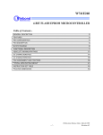
1. Assembly language development flow
Begin
Edit
.ASM File
ASM741S
.OBJ File
OK !
Mask Option Settings
OK !
Save
The procedure for preparing a program in assembly language includes editing, assembly, setting
mask options, debugging, and once the program is completely correct, generation of an .OBJ file.
-1-
Publication Release Date: August 1996
Revision A1
W741S User's Manual
2. Editing
To use ASM741S to develop a program in assembly language, one must first use a text editor to edit
the program source file with the extension .ASM. Commonly used editors include MS-DOS Edit and
PE II.
3. Assembler
The main task of the assembler is to transform the contents of the source file into machine code that
can be accepted by the W741xxxx microcontroller. A program will be translated into machine code if
it has no any syntax and semantic error.
Basis Structure of W741xxxx Microcontroller Programs
The following is a simple program for the W741xxxx microcontroller.
; CONSTANT DEFINITION
;*********************
; * Constant area
ç Constant definition area begins here.
;*********************
; CODE
; *********************
; * Code area
ç Instruction code area begins here.
; *********************
; TABLE
; *********************
; * Look-up table area
ç Look-up table code definition begins here.
; *********************
END
ç The termination of program.
Most programs comprise four main areas: the constant area, code area, look-up table area, and END.
These are described below.
1. Constant Area
Commonly used values include RAM, WR, LCD RAM, and immediate values. These can be assigned
names to make the program easier to read.
Syntax: Constant name EQU value
Constant name: The first letter in the name must be an English letter from A to Z (in upper- or
lowercase letters; no distinction is made between the two), and the name must not
exceed 16 letters in length.
Value: Three types of values may be used: numbers, immediate values, and internally defined
constants.
-2-
W741S User's Manual
(i) Numbers: Four formats may be used:
Binary: Only 0's and 1's may be used; a "B" is added at the end of the value.
Example: "010100B" represents a value of 20.
Octal: Digits from 0 to 7 may be used; an "O" is added at the end of the value.
Example: "70O" represents 56.
Decimal: Digits from 0 to 9 may be used; no letter is added at the end of the value.
Example: "023" or "23" represents 23.
Hexadecimal: Digits from 0 to 9 and letters from A to F may be used; an "H" is added at the end of
the value. (The first place in the value must be a number, not a letter.)
Example:
"3FH" represents 63
"0A3H" represents 163; a "0" must be added before the "A".
(ii) Immediate values: The format for immediate values is the same as that for numbers, except that
the value must be preceded by a "#" symbol.
(iii) Internally defined constants: Since constant names are typically used to simplify identification of
RAM, WR, LCD RAM, and immediate values, the system provides three types of internally
defined constant names.
. RAM constant names: A total of 128 names, from RAM00 to RAM7F.
. WR constant names: A total of 16 names, from WR0 to WRF.
. LCD RAM constant names: A total of 32 names, from LCDR00 to LCDR1F.
Examples:
Buffer1
Buffer2
Buffer3
Buffer4
FLAG1
FLAG2
EQU
EQU
EQU
EQU
EQU
EQU
32H
RAM33H
WR3
LCDR05
#3FH
#01011011B
à Define value of Buffer1 as RAM address 32H
à Define value of Buffer2 as the RAM address 33H
à Define value of Buffer3 as WR address 3
à Define value of Buffer4 as LCDRAM address 5
à Define value of FLAG1 as immediate data 3FH
à Define value of FLAG2 as immediate data 1011011B
2. Code Area
A typical program in the W741xxxx microcontroller assembly language includes the following items:
; Comment
Label: Mnemonic Operand
(i) Label: The label is optional. This is a mark for the program to enter, jump, or branch. After the
program is assembled, all labels will be changed into address values.
(ii) Mnemonic: These are actual instructions. For a list of the mnemonics used with the W741xxxx
microcontroller, see the W741xxxx user's manual.
(iii) Operand: This provides necessary parameter or data used by the microcontroller during
processing.
-3-
Publication Release Date: August 1996
Revision A1
W741S User's Manual
(iv) Comment: An explanation of the significance of a particular line of code. The assembler ignores
any information included after the semicolon (";") in each line.
1. Label: An address label represents a memory address.
Example: We assign the label "Begin" to the address 010H. Then in any instruction that refers to the
address 010H, such as "JMP Begin", the "Begin" can be used to stand for 010H.
Program labels are symbolic addresses in the program, so JMP, CALL, or JXX can be used to jump
or call an address. Note that the first place in a label must be a letter, and the maximum length of a
label is 16 letters or numbers.
Example:
ORG
BEGIN: MOV
010H
03H, ACC
|
JMP
BEGIN
2. Operand
Operand type:
RAM/WR:
RAM: 128 RAM operands, including 16 WR
In the program, users can directly write one of the following:
− a number 03FH to represent RAM address 3FH
− Define a constant in the constant area
− Use an internally defined constant, such as RAM3F
Examples:
MOV
3FH, ACC
à Loads current content of ACC into RAM address 3FH.
MOV
RAM3F, ACC
à Loads current content of ACC into RAM address 3FH.
BUF1
EQU
MOV
BUF1, ACC
3FH
à Loads current content of ACC into RAM address 3FH.
LCD RAM (LCDR): A total of 32 LCD RAM addresses.
In the program, users may not write a number as LCD RAM directly. Instead, they can only define a
constant in the constant area or use an internally defined constant (LCDR00 to LCDR1F).
Examples:
à This is read as MOV RAM03, ACC and not as MOV LCDR03, ACC
MOV
03H, ACC
MOV
LCDR03, ACC à Moves content of ACC to the third LCD RAM address.
-4-
W741S User's Manual
Immediate values:
In the program, if users wish to directly define the value of a particular register or RAM address, they
must add a "#" symbol at the beginning of the value or constant.
Examples:
MOV
MR0, #07H
Others:
For indirect addressing instructions, the "@" symbol must be added before the RAM address.
Examples:
MOV
@RAM3F, WR3
MOV
WR3, @RAM3F
3. Directives
END: END is a directive used at the end of a W741xxxx microcontroller program. It is used to
indicate to the ASM741S that the end of the program has been reached, and that any data that follow
are not part of the program.
";": The semicolon is a directive that indicates to the ASM741S that all data to the right of the
semicolon are not part of the program and should be ignored. Notes or comments inserted in the
program should be placed after a semicolon.
ORG: This directive is used to indicate from what address storage of the following instructions should
begin.
Example:
START:
ORG
010H
MOV
RAM03, ACC
à This instruction will be stored beginning at address 010H.
3. Look-up Table
Two directives, TABLE_START and TABLE_END, are used to define the look-up table code. The
code is expressed in nibbles, which are set off by commas.
Syntax:
TABLE_START 00H
1, 2, 5, 7, A, B
3, 4, 6, 8, C, D
TABLE_END
Note that the parameter after TABLE_START is a ROM address offset value that begins from the
ROM address at which look-up table data begin. Note that this offset value must be a multiple of 4.
The range of the value of each code, expressed in nibbles, is 0 to F.
-5-
Publication Release Date: August 1996
Revision A1
W741S User's Manual
Users can divide the look-up table area into any number of blocks of any size. Note that the size of
the look-up table must also be defined in light of the amount of ROM taken up by the code area.
W741xxxx Assembly Language Assembler File System
1. Assembly Language Files
ASM741S.EXE
Main assembler program
W741S.VER
Version check file
2. Files Created During Assembly
While assembling an *.ASM file, the ASM741S program creates a number of reference files before
finally creating the target file. The reference files, which are listed below, can be used for debugging
or for checking the results of different stages of the assembly process.
.LST File:
The program printout is divided into four columns: Line number, ROM address, machine code, and
original program. If an error is generated during assembly, then an error message will appear before
the line number in which the error is found. When an error occurs, the machine code column is not
generated.
.ERR File:
If an error occurs during assembly, then this file will indicate the line number in which the error
occurred and the appropriate error message. If no errors occur, then the contents of this file will be
blank.
.FRM File:
After assembly has been successfully completed, a request form will be generated. This file is to
enable users to check whether the data in the completed *.ASM file, such as the mask options, are
correct. Once the user confirms that the content of this file is correct, the file becomes an important
reference document between Winbond and the customer. Hence once the correctness of the data in
this file is confirmed, the file cannot be modified.
.LBL File:
This is a label file used to disassemble the *.OBJ file when customers wish to simulate their programs
through the WHC4403 emulation system.
3. Mask Option Selections
The W741xxxx microcontroller offers a selection of eight mask options, as described below:
(i) Crystal frequency option
1. Low-frequency clock
2. High-frequency clock
-6-
W741S User's Manual
(ii) LCD power input
1. Mode1
2. Mode2
(iii) LCD frequency
1. Fw/64
2. Fw/128
3. Fw/256
4. Fw/512
(iv) LCD Duty & Bias
1. 1/4 Duty, 1/3 Bias
2. 1/3 Duty, 1/3 Bias
3. Static
4. 1/3 Duty, 1/2 Bias
5. 1/2 Duty, 1/2 Bias
(v) LCD driver mode selection
I0 to I7 = 0 : LCD driver output mode
I0 to I7 = 1 : DC output mode
(vi) Oscillator type
1. RC oscillator type
2. Crystal oscillator type
(vii) Operation mode selection
1. Dual clock operation
2. Single clock operation
(viii) Watchdog timer
1. Disabled
2. Enabled
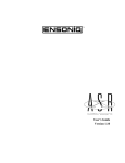
4. Operation
To run the assembly program, you can execute the command ASM741S.EXE at the DOS prompt.
The display shown in Figure 1 will appear on screen. Select the microcontroller body for which you
wish to assemble a program, or select "Q" to exit the ASM741S program. The assembly program can
also be called up from within the ICE741S ICE system by selecting the "Assemble" function. If the
program is run from within the ICE741S ICE system, it will not prompt you to select a microcontroller
body, but will proceed directly to assemble the program currently loaded into the ICE741S ICE
system.
-7-
Publication Release Date: August 1996
Revision A1
W741S User's Manual
Figure 1. Winbond 4-bit Microcontroller W741xxxx Series Assembler Copyright Message
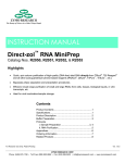
Once you have selected the type of microcontroller body, the assembler will ask you to input the
name of the file to be assembled. If the filename extension of the file is .ASM, then you can omit the
extension when typing the filename. If an incorrect name is entered or if the assembler cannot open
the file specified, then the error message shown in Figure 2 will appear.
Figure 2. Error Message Indicating Incorrect Filename
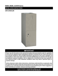
As soon as the filename is entered correctly, program assembly will begin. If an error occurs during
assembly, the assembler will display an error message on screen and place a copy of the error
message in a file with the extension .ERR. If assembly is completed without any errors, the assembler
will proceed to set the mask options. If this is the first time the current program has been assembled
or if the assembler cannot find a file with the main filename and the extension .OPT (i.e.,
Filename.OPT), then the assembler will display relevant messages and the default mask options for
confirmation or modification, as shown in Figure 3. At this time, you may select items from this
display and modify them if necessary.
-8-
W741S User's Manual
Figure 3. Mask Option Selections Displayed after Completion of Program Assembly
(the file Filename.OPT does not yet exist)
If the file Filename.OPT already exists, then the assembler will display the mask options and other
information contained in this file, as shown in Figure 4. You may use the display shown in Figure 4 to
modify the mask options, if necessary.
Figure 4. Mask Option Selections Displayed after Completion of Program Assembly
(the file Filename.OPT already exists)
-9-
Publication Release Date: August 1996
Revision A1
W741S User's Manual
If you do not wish to modify the mask options further, select "Q" from the display shown in Figure 3 or
4, and the assembler will complete the program assembly. The supplementary files described in
section 2 above will be created, and then the assembler will return to the screen shown in Figure 1.
You may then assemble another program or select "Q" to exit the assembler.
Error Messages
1. Number Errors
"Binary number overflow": Binary number exceeds 216.
"Octal number overflow": Octal number exceeds 216.
"Decimal number overflow": Decimal number exceeds 216.
"Hexadecimal number overflow": Hexadecimal number exceeds 216.
"Illegal binary digit": Error in the format of binary number, e.g., 01201B.
"Illegal octal digit": Error in the format of octal number, e.g., 0589O.
"Illegal decimal digit": Error in the format of decimal number, e.g., 012F.
"Illegal hexadecimal digit": Error in the format of hexadecimal number, e.g., 013FGH.
2. Symbol Errors
"Illegal character": Incorrect character, such as !ABC.
"Illegal token": Unable to recognize symbol.
"Symbol name is reserved word": Symbol is reserved word, such as "MOV ADD, ACC".
3. Syntax Errors
"No symbol in front of colon(:)": A label must precede the colon, such as "Label:".
"Duplicate label": This label has already been used in the same *.ASM file.
"Misplaced label": The label has been placed in an incorrect location, such as "MOV ACC, Label:".
"Undefined label": The label used in a JMP, Call, or JXX instruction has not been defined in this file.
"Label and constant can not share the same name": A label and a constant cannot share the same
name.
"Label should not be in front of ORG": A label may not be placed before the ORG directive, as in
"Begin: ORG 010H".
"Consecutive comma(,)": A line may not contain two consecutive commas, as in "MOV 03H, ACC".
"Consecutive constant": A line may not contain two consecutive constants,as in "BUF1 BUF2 EQU
20H".
"Consecutive operand": A line may not contain two consecutive operands, as in "MOV 03H ACC".
"Comma(,) should locate between operands": A comma has been placed incorrectly, as in
"MOV, 03H, ACC".
"No operand after comma(,)": An operand must follow a comma; "MOV 03H,"
for example, is incorrect.
- 10 -
W741S User's Manual
"Too many directive on the line": Only one directive may appear on one line; for example,
"MOV MOV, EQU" is incorrect.
"No instruction before operand": An operand must be preceded by an instruction. The following is
incorrect: "ACC, 03H."
"Constant should not be in front of instruction": An instruction should not be preceded by a constant,
as in "TEST MOV ACC, 03H".
"EQU directive missing constant value": The EQU directive must be followed by a constant value.
The following, for example, is incorrect: "TEST EQU".
"EQU directive missing constant": The EQU directive must be preceded by a constant name. The
following, for example, is incorrect: "EQU 03H".
"Duplicate constant": The same constant has already been defined in the same *.ASM file.
"ORG directive missing offset": The ORG directive must be followed by an offset value, as in "ORG
015H".
4. Instruction Syntax Errors
"Operand type mismatch": The operand is not the correct type for the instruction.
For example: "MOV IEF, ACC".
"Instruction missing first operand": The instruction must be followed by an operand.
For example, "CLR" is incorrect.
"Instruction missing second operand": The instruction must be followed by two operands.
For example, "MOV ACC" is incorrect.
"First operand overflow": The value of the first operand exceeds the permitted range.
"Second operand overflow": The value of the second operand exceeds the permitted range.
"Undefined constant": A constant name has been specified as the operand, but this constant has not
been defined.
"Jump or call instruction missing label": JMP, CALL, and JXX instructions must be followed by a label.
"Program terminates without END directive": An END directive must be included at the end of the
program.
"Offset overflow": The storage address of the instruction is beyond the ROM size of 2048 lines.
"Overwrite ROM address": There is a repetition in the ROM address of the instructions; the ORG
location may overlap or the instruction program may exceed 2048 lines.
"Extra token on line" Too many operands appear on the line, as in "MOV 03H, ACC, 04H, ACC."
5. Look-up Table Errors
"TABLE_START missing start address value": TABLE_START must be followed by an offset address.
"Look-up table missing TABLE_END": A look-up table must be followed by TABLE_END before a new
look-up table may be defined.
- 11 -
Publication Release Date: August 1996
Revision A1
W741S User's Manual
"Misplaced TABLE_END": A TABLE_END directive has been misplaced; it must be preceded by a
TABLE_START directive.
"Look-up table start address must be multiple of 4": The offset address defined by a look-up table
must be a multiple of 4.
"Look-up table without code": At least one nibble code must be defined within a look-up table area.
"Look-up table code must be 0−15": The value of the nibble codes in a look-up table must fall
between 0 and 15.
"Look-up table starting address overwrite instructions": The offset address of the look-up table
overlaps the preceding instruction area.
"Look-up tables" code overlap each other": The ROM addresses of two look-up tables overlap.
6. Other Errors
"The IC body cannot accept this instruction": The IC body does not provide this instruction.
"The 3, 5, 6th bit of IEF register is reserved": The 3, 5, 6th bit of IEF register is reserved, so these bits
cannot set "1".
"The 3, 5, 6th bit of HEF register is reserved": The 3, 5, 6th bit of HEF register is reserved, so these
bits cannot set "1".
"The 3, 5, 6th bit of EVF register is reserved": The 3, 5, 6th bit of EVF register is reserved, so these
bits cannot set "1".
"The 3rd bit of PAGE register is reserved": The 3rd bit of PAGE register is reserved, so the bit cannot
set "1".
"The first and 2nd bit of MR0 register is reserved": The first and 2nd bit of MR0 register is reserved,
so these bits cannot set "1".
Headquarters
Winbond Electronics (H.K.) Ltd.
Rm. 803, World Trade Square, Tower II,
No. 4, Creation Rd. III,
123 Hoi Bun Rd., Kwun Tong,
Science-Based Industrial Park,
Kowloon, Hong Kong
Hsinchu, Taiwan
TEL: 852-27513100
TEL: 886-3-5770066
FAX: 852-27552064
FAX: 886-3-5792766
http://www.winbond.com.tw/
Voice & Fax-on-demand: 886-2-27197006
Taipei Office
11F, No. 115, Sec. 3, Min-Sheng East Rd.,
Taipei, Taiwan
TEL: 886-2-27190505
FAX: 886-2-27197502
Note: All data and specifications are subject to change without notice.
- 12 -
Winbond Electronics North America Corp.
Winbond Memory Lab.
Winbond Microelectronics Corp.
Winbond Systems Lab.
2727 N. First Street, San Jose,
CA 95134, U.S.A.
TEL: 408-9436666
FAX: 408-5441798