1
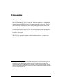
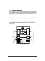
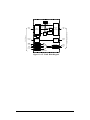
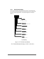
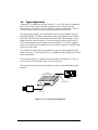
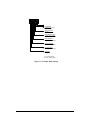
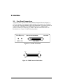
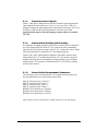
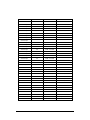
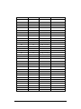
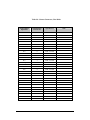
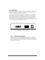
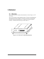
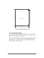
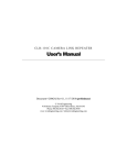
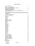
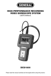
C LT- 3 0 3 R & C LT- 3 0 3 L C A M E R A L I N K T R A N S L ATO R User’s Manual Document # 201087, Rev 0.1, 2/10/2012 preliminary Vivid Engineering 159 Memorial Drive, Suite F • Shrewsbury, MA 01545 Phone 508.842.0165 • Fax 508.842.8930 Table of Contents 1. Introduction 1 1.1. Overview 1 1.2. Features 3 1.3. Functional Description 4 1.3.1. Mode Switch Settings 9 1.4. Typical Application 10 1.5. Specifications 12 2. Interface 13 2.1. Front Panel Connections 13 2.1.1. Camera Connector Signals 14 2.1.2. Camera Cable Shielding and Grounding 14 2.1.3. Camera Cable Recommended Connectors 14 2.2. Rear Panel 42 2.2.1. Video Connector Signals 42 3. Mechanical 43 3.1. Dimensions 43 3.2. External Power Supply 44 4. Revision History 45 1. Introduction 1.1. Overview The CLT-303R and CLT-303L Camera Link 1 Translators enable the use of traditional RS-422 and LVDS digital cameras with Camera Link frame grabbers. The “R” and “L” versions support parallel RS-422 and LVDS digital camera data, respectively. The CLT303’s can convert a wide range of cameras from parallel digital output to Camera Link base configuration with up-to 24-bit data. Cameras with pixel clock rates as low as 2.5 MHz and as high as 85 MHz are supported. Features include RS-232 communication support, a camera signal detect indicator, and isolated DC power input. The CLT-303’s are housed in sturdy, compact aluminum enclosures. A locking-plug power supply is optional. The Camera Link interface standard enables the interoperability of cameras and frame grabbers, regardless of vendor. The Automated Imaging Association (AIA) sponsors the Camera Link program including the oversight Camera Link Committee, the self-certification program, and the product registry. The Camera Link specification may be downloaded from the AIA website, found at www.machinevisiononline.org 1 1 Vivid Engineering POWER LINK Vivid Engineering POWER LINK Camera Link Translator CLT-303L LVDS CAMERA Camera Link Translator RS-422 CAMERA 2 CLT-303R 1.2. Features • Enable use of RS-422 and LVDS cameras with Camera Link frame grabbers • Also useful for converting parallel video from FPGA and imaging development boards • Camera Link “base” configuration interface, supports up-to 24-bit data • “R” version supports RS-422 cameras • “L” version supports LVDS cameras • 2.5 MHz to 85 MHz camera pixel clock range for “L” version • 2.5 MHz to 32 MHz camera pixel clock range for “R” version • RS-232 camera communication support • Selectable camera clock and timing signal polarities • Link indicator • Isolated DC power input • Minimal data pass-through latency • Flow-through connector placement • Sturdy, compact aluminum enclosure with mounting flange • Multi-nation power supply included, locking-plug power supply optional • 3-year warrantee 3 1.3. Functional Description The CLT-303L & CLT-303R Camera Link Translators enable the use of traditional RS422 and LVDS digital cameras with Camera Link frame grabbers. Block diagrams of the CLT-303R and CLT-303L are provided in Figures 1-1 and 1-2, respectively. The CLT303R is intended for use with RS-422 digital cameras and the CLT-303L for use with LVDS (EIA-644) digital cameras. The camera interface receives video data in parallel digital format using RS-422 or LVDS, depending on CLT-303 version. The camera interface incorporates a 68-pin SCSI-style connector. The CLT-303 frame grabber interfaces incorporates the connector, signals, pinout, and chipset in compliance with the Camera Link specification. The CLT-303 incorporates the “base” configuration signal set, consisting of video data, camera control, and serial communications. Mode Select Switch comm select Pixel Data Video Data RS-422 RS-422 RS-422 Receivers Receivers Receivers Frame Valid, Line Valid To RS-422 Camera Edge Select Channel Link Transmitter Video Data LVDS Receiver Camera Control Clock Multiplier Link Detect Camera Control Serial Comm RS-422 Transmitter RS-422 Rcvr (RS-422) RS-422 Xmtr Serial Comm RS-232 Rcvr LVDS Xmtr Mux (RS-232) LVDS Rcvr RS-232 Xmtr CLT-303R Camera Link Translator Figure 1-1: CLT-303R Block Diagram 4 Serial Comm Link To Camera Link Frame Grabber Clock Polarity Select Mode Select Switch comm select Pixel Data Video Data RS-422 RS-422 LVDS Receivers Receivers Receivers Frame Valid, Line Valid To LVDS Camera Edge Select Channel Link Transmitter Video Data LVDS Receiver Camera Control Clock Multiplier Link Detect Camera Control Serial Comm LVDS Transmitter LVDS Rcvr (LVDS) LVDS Xmtr Serial Comm RS-232 Rcvr LVDS Xmtr Mux (RS-232) LVDS Rcvr RS-232 Xmtr CLT-303L Camera Link Translator Figure 1-2: CLT-303L Block Diagram 5 Serial Comm Link To Camera Link Frame Grabber Clock Polarity Select The CLT-303 receives parallel digital camera data on the 68-pin camera connector and maps the pixel data into the corresponding Camera Link “base” configuration format. The CLT supports single-channel (monochrome) cameras with 8/10/12/14/16-bit pixels, dualchannel 8/10/12-bit cameras, and 8-bit color cameras. The latency (i.e. delay) of the video, control, and communication signals passing through the CLT-303 is minimal. This is an important criteria in time-critical applications. See Table 1.1 for CLT-303 latency specifications. Camera timing signal characteristics are selected using the rear-panel mode switch. One switch position is used to select the polarity of the line valid signal, and a second switch position is used to select the polarity of the frame valid signal. In most cases, a “high” state on the line enable and frame enable signals is used to envelope valid lines and frames of video data, respectively. The settings enable the user to select either active-high or active-low polarities for each timing signal. Note that the frame enable signal is not used in line scan applications. Switch settings are defined in Section 1.3.1. Camera Link incorporates a data valid signal which is used to qualify the video data. This signal is generated by the CLT-303 and sent to the Camera Link frame grabber. Most LVDS and RS-422 digital cameras do not incorporate a data valid type signal. The CLT303 incorporates a provision for the rare cases in which a data valid is provided by the camera. When the data valid pass-through dip switch position is raised, the CLT-303 passes the data valid signal from the camera to the frame grabber. The Camera Link data valid input is active-high, qualifying the incoming video data when the signal is high. A second dipswitch position, data valid polarity, supports either active-high or active-low data valid signals from the camera. When the data valid pass-through dipswitch is in the normal (low) position, the CLT-303 maintains the data valid signal sent to the frame grabber in the high position. The only exception is when the clock multiplier is being used which is discussed next. Camera pixel clock characteristics are selected using the rear-panel mode switch. One switch position is used to select which pixel clock edge, rising or falling, is used to sample the data and timing signals received from the camera. Two additional switch positions are used to enable the CLT-303 clock multiplier circuit. The clock multiplier supports the use of camera with pixel clock frequency below the Camera Link 20MHz minimum by “multiplying” the camera clock frequency before it is sent to the Camera Link frame grabber.. For cameras with pixel clocks in the 10-19.99 MHz range, the clock multiplier is used to 2x (i.e. double) the clock frequency. For cameras with pixel clocks in the 5-9.99 MHz range, the clock multiplier is used to 4x (i.e. quadruple) the clock frequency. For cameras with pixel clocks in the 2.5-4.99 MHz range, the clock multiplier is used to 8x the clock frequency. 6 The result of using the clock multiplier is a 2x/4x/8x oversampling of camera data and timing signals sent to the Camera Link frame grabber. When in 2x/4x/8x mode, the CLT303L & CLT-303R toggles the “data valid” signal defined in the Camera Link Specification accordingly. If the frame grabber supports the data valid signal, the oversampling affect is removed automatically. Otherwise, the oversampling is easily removed in the frame grabber by adjusting the line timing (multiply by 2/4/8) and decimating (divide by 2/4/8) the pixels in the “X” dimension. Two switch positions are used to select camera clock characteristics. Switch settings are defined in Section 1.3.1. The CLT-303 receives four LVDS camera control signals from the Camera Link frame grabber and retransmits two of the signals (CC1 and CC2) to the camera using LVDS or RS-422 signaling, depending on CLT-303 version. These signals are often used to externally synchronize the camera (i.e. EXSYNC). The CLT-303 routes the serial communication signals between the LVDS/RS-422 digital camera and the Camera Link frame grabber. This supports host computer access to mode control and status registers in the camera via the serial port included in the Camera Link frame grabber. The camera may or may not incorporate a serial port. The CLT-303 supports differential signaling (LVDS or RS-422, depending on CLT-303 version) for the camera serial port as well as RS-232 single-ended signaling which is used with some LVDS/RS-422 cameras. A rear-panel dipswitch is used to select the camera serial port signaling standard (RS-422/LVDS or RS-232). Note that the LVDS/RS-422 and RS-232 serial ports use different pins on the 68-pin camera connector. The camera cable must be correctly wired for the desired serial port signaling standard. The CLT-303L & CLT-303R frame grabber interface incorporates LVDS devices for the serial communication signals (per Camera Link). The camera interface serial signals are implemented using LVDS or RS-422 devices, depending on CLT-303 version. A front-panel link status indicator illuminates when the camera video signal is detected. The front panel also includes a power indicator. The CLT-303 is powered by an external wall plug-in power supply. A multi-nation power supply is standard. Optionally, the CLT-303 is available with a locking-plug power supply. The locking plug reduces the risk of accidental disconnection from the rear-panel power jack. The CLT-303 is also available without power supply. 7 The CLT-303 DC power input is electrically isolated from the internal circuitry. This feature ensures compatibility with user power systems. Note: The CLT-303 requires a steady, continuous pixel clock from the camera. 8 1.3.1. Mode Switch Settings The CLT-303 incorporates a rear-panel mode select switch. The switch allows the user to identify camera timing signal, serial communication, and clock characteristics. The mode switch has eight positions. The functional assignments are defined in Figure 1-3. 1 2 3 4 5 6 7 8 Clock Multiplier 1 1 - 8x 0 1 - 4x 1 0 - 2x 0 0 - Disabled (most common) 1 0 Serial Comm Select - RS-232 - LVDS (CLT-302L) or RS-422 (CLT-302R) 1 0 Data Valid Pass-Through - enabled - disabled (most common) 1 0 Data Valid Polarity - active-low - active-high (most common) 1 0 Frame Valid Polarity - active-low - active-high (most common) 1 0 Line Valid Polarity - active-low - active-high (most common) 1 0 Clock Edge - falling edge - rising edge (most common) 1 = "up" switch position 0 = "down" switch position Figure 1-3: CLT-303 Mode Switch Definition Note: Normal (default) dipswitch settings are “all-low” as shown above 9 1.4. Typical Application A typical CLT-303 application is shown in Figure 1-4. An LVDS camera is connected to the CLT-303L using a camera cable that incorporates a 68-pin connector and pin assignments for use with the CLT-303L and RS-232 camera communication . The CLT303L is connected to the frame grabber using a standard Camera Link cable. The camera in this example is 8-bit, dual-channel, area-scan with a 20MHz pixel clock and LVDS signaling. The frame enable and line enable timing signals are conventional active-high. The camera does not generate a data valid signal. Data sampling is via the falling edge of the camera pixel clock. The serial control port on the camera is RS-232. The corresponding mode switch settings are shown in Figure 1-5. The clock multiplier feature is not required in this example since the pixel clock is within the 20-85 MHz range required by Camera Link. The Camera Link frame grabber is programmed for area-scan, base-configuration, dualchannel, 8-bit mode. The pixel clock rate is set at 20MHz and video timing is set to match camera characteristics. Camera control signal CC1 is routed from the frame grabber, through the CLT-303L, to the camera for use as an EXSYNC pulse, exposure control, etc. The serial port in the Camera Link frame grabber is used to control and monitor camera functions. CLT-303L Camera Link Translator Camera Link Frame Grabber Vivid Engineering POWER LVDS Camera CLT-303L Camera Link Translator LINK Camera Link Cable LVDS CAMERA Camera Cable Figure 1-4: CLT-303 Typical Application 10 1 2 3 4 5 6 7 8 Clock Multiplier 0 0 - Disabled (most common) 1 Serial Comm Select - RS-232 0 Data Valid Pass-Through - disabled (most common) 0 Data Valid Polarity - active-high (most common) 0 Frame Valid Polarity - active-high (most common) 0 Line Valid Polarity - active-high (most common) 1 Clock Edge - falling edge 1 = "up" switch position 0 = "down" switch position Figure 1-5: Example Mode Settings 11 1.5. Specifications Table 1-1: CLT-303L & CLT-303R Specifications Feature Specification Camera Interface - “R” version = Parallel RS-422 - “L” version = Parallel LVDS (EIA-644) Camera Connector 68-pin SCSI-style (HD68) Frame Grabber Interface Camera Link “base” configuration Frame Grabber Connector 26-pin MDR type Camera Frequency - “R” version: 2.5 - 32 MHz - “L” version: 2.5 - 85 MHz Mode Selection Rear-panel 8-position DIP switch Latency Video path: 3 camera pixel clock cycles Control signals: 20 ns max Power Supply Universal wall style w/ outlet plug set Power Plug 2.1 x 5.5 mm, center-positive. Locking style optional Power Requirements 4.5 – 9.0 VDC, internally isolated - 300 mA @ 5 VDC (typical) Cabinet Dimensions 5.28” (L) x 1.12” (H) x 6.13” (D) Weight 13 oz Operating Temperature Range 0 to 50° C Storage Temperature Range -25 to 75° C Relative Humidity 0 to 90%, non-condensing Compliance FCC Class A, ROHS, CE EN55024 pending 12 2. Interface 2.1. Front Panel Connections A CLT-303L & CLT-303R Camera Link Translator front panel is shown in Figure 2-1 (CLT-303L shown). The front panel contains a 68-pin video connector for connecting to the camera , an LED power indicator, and an LED link indicator. The camera connector is a 68-pin SCSI-3 type (HD68), TE Connectivity p/n 5787170-7. Included are two jackscrew sockets (TE Connectivity p/n 749087-2) that mate with camera cable 2-56 thread jackscrews. Figure 2-2 identifies the pin positions. Vivid Engineering POWER CLT-303L Camera Link Translator LINK LVDS CAMERA Figure 2-1: CLT-303L Front Panel pin 34 pin 1 pin 68 pin 35 Figure 2-2: HD68 Connector Pin Positions 13 2.1.1. Camera Connector Signals Tables 2-1 through 2-5 identify the 68-pin camera connector signal assignments for single-channel pixel data modes (1x8, 1x10, 1x12, 1x14, and 1x16). Tables 2-6 through 2-8 identify the signal assignment for dual-channel modes (2x8, 2x10, 2x12), and Table 2-9 identifies the signal assignment for color mode (3x8). The appropriate table must be used when making a camera cable for use with the CLT-303. 2.1.2. Camera Cable Shielding and Grounding At a minimum, one digital ground pin at the camera connector must be connected to one of the digital ground pins on the CLT-303 connector in order to maintaining signal reference levels between camera and CLT-303. Camera cable “inner” shields (if present) should also be connected to CLT-303 digital ground pins. Camera cable “outer” shields should be attached to the metallic connector shell, which contacts the CLT-303 aluminum enclosure. CLT-303 enclosure body and endplate contacting surfaces are unpainted, providing a Faraday cage to shield the internal circuitry. The enclosure is isolated from the CLT-303 circuitry, avoiding possible safety concerns. 2.1.3. Camera Cable Recommended Connectors The following is a list of recommended CLT-303 mating connectors (plugs) and housings (backshells) to use when making camera cables: Plug, TE Connectivity p/n 1-5750913-7 Plug, TE Connectivity p/n 5750913-7 Plug, TE Connectivity p/n 5749111-6 Plug, TE Connectivity p/n 5749621-7 Backshell, TE Connectivity p/n 5786152-3 Backshell, TE Connectivity p/n 5750752-1 Backshell, TE Connectivity p/n 5750752-3 Other suitable connector manufacturers include NorComp, Acon, and Harting. 14 Table 2-1: Camera Connector, 8-bit Single-Channel Mode Camera Interface Signal Name Camera Interface Connector Pin Signal Direction A0 + 1 CAM → CLT-303 A0 - 35 CAM → CLT-303 A1 + 2 CAM → CLT-303 A1 - 36 CAM → CLT-303 A2 + 3 CAM → CLT-303 A2 - 37 CAM → CLT-303 A3 + 4 CAM → CLT-303 A3 - 38 CAM → CLT-303 A4 + 5 CAM → CLT-303 A4 - 39 CAM → CLT-303 A5 + 6 CAM → CLT-303 A5 - 40 CAM → CLT-303 A6 + 7 CAM → CLT-303 A6 - 41 CAM → CLT-303 1 8 CAM → CLT-303 A7 - 1 42 CAM → CLT-303 Unused Input 9 CAM → CLT-303 Unused Input 43 CAM → CLT-303 Unused Input 10 CAM → CLT-303 Unused Input 44 CAM → CLT-303 Unused Input 11 CAM → CLT-303 Unused Input 45 CAM → CLT-303 Unused Input 12 CAM → CLT-303 Unused Input 46 CAM → CLT-303 Unused Input 13 CAM → CLT-303 Unused Input 47 CAM → CLT-303 Unused Input 14 CAM → CLT-303 Unused Input 48 CAM → CLT-303 Unused Input 15 CAM → CLT-303 Unused Input 49 CAM → CLT-303 A7 + 15 Notes Unused Input 16 CAM → CLT-303 Unused Input 50 CAM → CLT-303 Unused Input 17 CAM → CLT-303 Unused Input 51 CAM → CLT-303 Unused Input 18 CAM → CLT-303 Unused Input 52 CAM → CLT-303 Unused Input 19 CAM → CLT-303 Unused Input 53 CAM → CLT-303 Unused Input 20 CAM → CLT-303 Unused Input 54 CAM → CLT-303 Unused Input 21 CAM → CLT-303 Unused Input 55 CAM → CLT-303 Unused Input 22 CAM → CLT-303 Unused Input 56 CAM → CLT-303 Unused Input 23 CAM → CLT-303 Unused Input 57 CAM → CLT-303 Unused Input 24 CAM → CLT-303 Unused Input 58 CAM → CLT-303 Mode Control 1 + 25 CLT-303 → CAM CC1 from FG Mode Control 1 - 59 CLT-303 → CAM ” Mode Control 2 + 26 CLT-303 → CAM CC2 from FG Mode Control 2 - 60 CLT-303 → CAM ” Serial Control Out + 27 CLT-303 → CAM serial comm, FG to cam Serial Control Out - 61 CLT-303 → CAM “ Serial Control In + 28 CAM → CLT-303 serial comm, cam to FG Serial Control In - 62 CAM → CLT-303 “ RS-232 Comm Out 29 CLT-303 → CAM RS-232 comm, FG to cam RS-232 Comm In 63 CAM → CLT-303 RS-232 comm, cam to FG Frame Enable + 30 CAM → CLT-303 “frame valid” Frame Enable - 64 CAM → CLT-303 “ Line Enable + 31 CAM → CLT-303 “line valid” Line Enable - 65 CAM → CLT-303 “ Data Valid + 32 CAM → CLT-303 “data valid” Data Valid - 66 CAM → CLT-303 “ Pixel Strobe + 33 CAM → CLT-303 “pixel clock” Pixel Strobe - 67 CAM → CLT-303 “ 16 Ground 34 N/A tied to digital ground Ground 68 N/A tied to digital ground 1 Pixel “A” MSB “FG” = Frame Grabber “cam” = Camera 17 Table 2-2: Camera Connector, 10-bit Single-Channel Mode Camera Interface Signal Name Camera Interface Connector Pin Signal Direction A0 + 1 CAM → CLT-303 A0 - 35 CAM → CLT-303 A1 + 2 CAM → CLT-303 A1 - 36 CAM → CLT-303 A2 + 3 CAM → CLT-303 A2 - 37 CAM → CLT-303 A3 + 4 CAM → CLT-303 A3 - 38 CAM → CLT-303 A4 + 5 CAM → CLT-303 A4 - 39 CAM → CLT-303 A5 + 6 CAM → CLT-303 A5 - 40 CAM → CLT-303 A6 + 7 CAM → CLT-303 A6 - 41 CAM → CLT-303 A7 + 8 CAM → CLT-303 A7 - 42 CAM → CLT-303 A8 + 9 CAM → CLT-303 A8 - 43 CAM → CLT-303 1 10 CAM → CLT-303 A9 - 1 44 CAM → CLT-303 Unused Input 11 CAM → CLT-303 Unused Input 45 CAM → CLT-303 Unused Input 12 CAM → CLT-303 Unused Input 46 CAM → CLT-303 Unused Input 13 CAM → CLT-303 Unused Input 47 CAM → CLT-303 Unused Input 14 CAM → CLT-303 Unused Input 48 CAM → CLT-303 Unused Input 15 CAM → CLT-303 Unused Input 49 CAM → CLT-303 A9 + 18 Notes Unused Input 16 CAM → CLT-303 Unused Input 50 CAM → CLT-303 Unused Input 17 CAM → CLT-303 Unused Input 51 CAM → CLT-303 Unused Input 18 CAM → CLT-303 Unused Input 52 CAM → CLT-303 Unused Input 19 CAM → CLT-303 Unused Input 53 CAM → CLT-303 Unused Input 20 CAM → CLT-303 Unused Input 54 CAM → CLT-303 Unused Input 21 CAM → CLT-303 Unused Input 55 CAM → CLT-303 Unused Input 22 CAM → CLT-303 Unused Input 56 CAM → CLT-303 Unused Input 23 CAM → CLT-303 Unused Input 57 CAM → CLT-303 Unused Input 24 CAM → CLT-303 Unused Input 58 CAM → CLT-303 Mode Control 1 + 25 CLT-303 → CAM CC1 from FG Mode Control 1 - 59 CLT-303 → CAM ” Mode Control 2 + 26 CLT-303 → CAM CC2 from FG Mode Control 2 - 60 CLT-303 → CAM ” Serial Control Out + 27 CLT-303 → CAM serial comm, FG to cam Serial Control Out - 61 CLT-303 → CAM “ Serial Control In + 28 CAM → CLT-303 serial comm, cam to FG Serial Control In - 62 CAM → CLT-303 “ RS-232 Comm Out 29 CLT-303 → CAM RS-232 comm, FG to cam RS-232 Comm In 63 CAM → CLT-303 RS-232 comm, cam to FG Frame Enable + 30 CAM → CLT-303 “frame valid” Frame Enable - 64 CAM → CLT-303 “ Line Enable + 31 CAM → CLT-303 “line valid” Line Enable - 65 CAM → CLT-303 “ Data Valid + 32 CAM → CLT-303 “data valid” Data Valid - 66 CAM → CLT-303 “ Pixel Strobe + 33 CAM → CLT-303 “pixel clock” Pixel Strobe - 67 CAM → CLT-303 “ 19 Ground 34 N/A tied to digital ground Ground 68 N/A tied to digital ground 1 Pixel “A” MSB “FG” = Frame Grabber “cam” = Camera 20 Table 2-3: Camera Connector, 12-bit Single-Channel Mode Camera Interface Signal Name Camera Interface Connector Pin Signal Direction A0 + 1 CAM → CLT-303 A0 - 35 CAM → CLT-303 A1 + 2 CAM → CLT-303 A1 - 36 CAM → CLT-303 A2 + 3 CAM → CLT-303 A2 - 37 CAM → CLT-303 A3 + 4 CAM → CLT-303 A3 - 38 CAM → CLT-303 A4 + 5 CAM → CLT-303 A4 - 39 CAM → CLT-303 A5 + 6 CAM → CLT-303 A5 - 40 CAM → CLT-303 A6 + 7 CAM → CLT-303 A6 - 41 CAM → CLT-303 A7 + 8 CAM → CLT-303 A7 - 42 CAM → CLT-303 A8 + 9 CAM → CLT-303 A8 - 43 CAM → CLT-303 A9 + 10 CAM → CLT-303 A9 - 44 CAM → CLT-303 A10 + 11 CAM → CLT-303 A10 - 45 CAM → CLT-303 1 12 CAM → CLT-303 1 A11 - 46 CAM → CLT-303 Unused Input 13 CAM → CLT-303 Unused Input 47 CAM → CLT-303 Unused Input 14 CAM → CLT-303 Unused Input 48 CAM → CLT-303 Unused Input 15 CAM → CLT-303 Unused Input 49 CAM → CLT-303 A11 + 21 Notes Unused Input 16 CAM → CLT-303 Unused Input 50 CAM → CLT-303 Unused Input 17 CAM → CLT-303 Unused Input 51 CAM → CLT-303 Unused Input 18 CAM → CLT-303 Unused Input 52 CAM → CLT-303 Unused Input 19 CAM → CLT-303 Unused Input 53 CAM → CLT-303 Unused Input 20 CAM → CLT-303 Unused Input 54 CAM → CLT-303 Unused Input 21 CAM → CLT-303 Unused Input 55 CAM → CLT-303 Unused Input 22 CAM → CLT-303 Unused Input 56 CAM → CLT-303 Unused Input 23 CAM → CLT-303 Unused Input 57 CAM → CLT-303 Unused Input 24 CAM → CLT-303 Unused Input 58 CAM → CLT-303 Mode Control 1 + 25 CLT-303 → CAM CC1 from FG Mode Control 1 - 59 CLT-303 → CAM ” Mode Control 2 + 26 CLT-303 → CAM CC2 from FG Mode Control 2 - 60 CLT-303 → CAM ” Serial Control Out + 27 CLT-303 → CAM serial comm, FG to cam Serial Control Out - 61 CLT-303 → CAM “ Serial Control In + 28 CAM → CLT-303 serial comm, cam to FG Serial Control In - 62 CAM → CLT-303 “ RS-232 Comm Out 29 CLT-303 → CAM RS-232 comm, FG to cam RS-232 Comm In 63 CAM → CLT-303 RS-232 comm, cam to FG Frame Enable + 30 CAM → CLT-303 “frame valid” Frame Enable - 64 CAM → CLT-303 “ Line Enable + 31 CAM → CLT-303 “line valid” Line Enable - 65 CAM → CLT-303 “ Data Valid + 32 CAM → CLT-303 “data valid” Data Valid - 66 CAM → CLT-303 “ Pixel Strobe + 33 CAM → CLT-303 “pixel clock” Pixel Strobe - 67 CAM → CLT-303 “ 22 Ground 34 N/A tied to digital ground Ground 68 N/A tied to digital ground 1 Pixel “A” MSB “FG” = Frame Grabber “cam” = Camera 23 Table 2-4: Camera Connector, 14-bit Single-Channel Mode Camera Interface Signal Name Camera Interface Connector Pin Signal Direction A0 + 1 CAM → CLT-303 A0 - 35 CAM → CLT-303 A1 + 2 CAM → CLT-303 A1 - 36 CAM → CLT-303 A2 + 3 CAM → CLT-303 A2 - 37 CAM → CLT-303 A3 + 4 CAM → CLT-303 A3 - 38 CAM → CLT-303 A4 + 5 CAM → CLT-303 A4 - 39 CAM → CLT-303 A5 + 6 CAM → CLT-303 A5 - 40 CAM → CLT-303 A6 + 7 CAM → CLT-303 A6 - 41 CAM → CLT-303 A7 + 8 CAM → CLT-303 A7 - 42 CAM → CLT-303 A8 + 9 CAM → CLT-303 A8 - 43 CAM → CLT-303 A9 + 10 CAM → CLT-303 A9 - 44 CAM → CLT-303 A10 + 11 CAM → CLT-303 A10 - 45 CAM → CLT-303 A11 + 12 CAM → CLT-303 A11 - 46 CAM → CLT-303 A12 + 13 CAM → CLT-303 A12 - 47 CAM → CLT-303 1 14 CAM → CLT-303 1 A13 - 48 CAM → CLT-303 Unused Input 15 CAM → CLT-303 Unused Input 49 CAM → CLT-303 A13 + 24 Notes Unused Input 16 CAM → CLT-303 Unused Input 50 CAM → CLT-303 Unused Input 17 CAM → CLT-303 Unused Input 51 CAM → CLT-303 Unused Input 18 CAM → CLT-303 Unused Input 52 CAM → CLT-303 Unused Input 19 CAM → CLT-303 Unused Input 53 CAM → CLT-303 Unused Input 20 CAM → CLT-303 Unused Input 54 CAM → CLT-303 Unused Input 21 CAM → CLT-303 Unused Input 55 CAM → CLT-303 Unused Input 22 CAM → CLT-303 Unused Input 56 CAM → CLT-303 Unused Input 23 CAM → CLT-303 Unused Input 57 CAM → CLT-303 Unused Input 24 CAM → CLT-303 Unused Input 58 CAM → CLT-303 Mode Control 1 + 25 CLT-303 → CAM CC1 from FG Mode Control 1 - 59 CLT-303 → CAM ” Mode Control 2 + 26 CLT-303 → CAM CC2 from FG Mode Control 2 - 60 CLT-303 → CAM ” Serial Control Out + 27 CLT-303 → CAM serial comm, FG to cam Serial Control Out - 61 CLT-303 → CAM “ Serial Control In + 28 CAM → CLT-303 serial comm, cam to FG Serial Control In - 62 CAM → CLT-303 “ RS-232 Comm Out 29 CLT-303 → CAM RS-232 comm, FG to cam RS-232 Comm In 63 CAM → CLT-303 RS-232 comm, cam to FG Frame Enable + 30 CAM → CLT-303 “frame valid” Frame Enable - 64 CAM → CLT-303 “ Line Enable + 31 CAM → CLT-303 “line valid” Line Enable - 65 CAM → CLT-303 “ Data Valid + 32 CAM → CLT-303 “data valid” Data Valid - 66 CAM → CLT-303 “ Pixel Strobe + 33 CAM → CLT-303 “pixel clock” Pixel Strobe - 67 CAM → CLT-303 “ 25 Ground 34 N/A tied to digital ground Ground 68 N/A tied to digital ground 1 Pixel “A” MSB “FG” = Frame Grabber “cam” = Camera 26 Table 2-5: Camera Connector, 16-bit Single-Channel Mode Camera Interface Signal Name Camera Interface Connector Pin Signal Direction A0 + 1 CAM → CLT-303 A0 - 35 CAM → CLT-303 A1 + 2 CAM → CLT-303 A1 - 36 CAM → CLT-303 A2 + 3 CAM → CLT-303 A2 - 37 CAM → CLT-303 A3 + 4 CAM → CLT-303 A3 - 38 CAM → CLT-303 A4 + 5 CAM → CLT-303 A4 - 39 CAM → CLT-303 A5 + 6 CAM → CLT-303 A5 - 40 CAM → CLT-303 A6 + 7 CAM → CLT-303 A6 - 41 CAM → CLT-303 A7 + 8 CAM → CLT-303 A7 - 42 CAM → CLT-303 A8 + 9 CAM → CLT-303 A8 - 43 CAM → CLT-303 A9 + 10 CAM → CLT-303 A9 - 44 CAM → CLT-303 A10 + 11 CAM → CLT-303 A10 - 45 CAM → CLT-303 A11 + 12 CAM → CLT-303 A11 - 46 CAM → CLT-303 A12 + 13 CAM → CLT-303 A12 - 47 CAM → CLT-303 A13 + 14 CAM → CLT-303 A13 - 48 CAM → CLT-303 A14 + 15 CAM → CLT-303 A14 - 49 CAM → CLT-303 27 Notes 1 16 CAM → CLT-303 1 A15 - 50 CAM → CLT-303 Unused Input 17 CAM → CLT-303 Unused Input 51 CAM → CLT-303 Unused Input 18 CAM → CLT-303 Unused Input 52 CAM → CLT-303 Unused Input 19 CAM → CLT-303 Unused Input 53 CAM → CLT-303 Unused Input 20 CAM → CLT-303 Unused Input 54 CAM → CLT-303 Unused Input 21 CAM → CLT-303 Unused Input 55 CAM → CLT-303 Unused Input 22 CAM → CLT-303 Unused Input 56 CAM → CLT-303 Unused Input 23 CAM → CLT-303 Unused Input 57 CAM → CLT-303 Unused Input 24 CAM → CLT-303 Unused Input 58 CAM → CLT-303 A15 + Mode Control 1 + 25 CLT-303 → CAM CC1 from FG Mode Control 1 - 59 CLT-303 → CAM ” Mode Control 2 + 26 CLT-303 → CAM CC2 from FG Mode Control 2 - 60 CLT-303 → CAM ” Serial Control Out + 27 CLT-303 → CAM serial comm, FG to cam Serial Control Out - 61 CLT-303 → CAM “ Serial Control In + 28 CAM → CLT-303 serial comm, cam to FG Serial Control In - 62 CAM → CLT-303 “ RS-232 Comm Out 29 CLT-303 → CAM RS-232 comm, FG to cam RS-232 Comm In 63 CAM → CLT-303 RS-232 comm, cam to FG Frame Enable + 30 CAM → CLT-303 “frame valid” Frame Enable - 64 CAM → CLT-303 “ Line Enable + 31 CAM → CLT-303 “line valid” Line Enable - 65 CAM → CLT-303 “ Data Valid + 32 CAM → CLT-303 “data valid” Data Valid - 66 CAM → CLT-303 “ Pixel Strobe + 33 CAM → CLT-303 “pixel clock” Pixel Strobe - 67 CAM → CLT-303 “ 28 Ground 34 N/A tied to digital ground Ground 68 N/A tied to digital ground 1 Pixel “A” MSB “FG” = Frame Grabber “cam” = Camera 29 Table 2-6: Camera Connector, 8-bit Dual-Channel Mode Camera Interface Signal Name Camera Interface Connector Pin Signal Direction A0 + 1 CAM → CLT-303 A0 - 35 CAM → CLT-303 A1 + 2 CAM → CLT-303 A1 - 36 CAM → CLT-303 A2 + 3 CAM → CLT-303 A2 - 37 CAM → CLT-303 A3 + 4 CAM → CLT-303 A3 - 38 CAM → CLT-303 A4 + 5 CAM → CLT-303 A4 - 39 CAM → CLT-303 A5 + 6 CAM → CLT-303 A5 - 40 CAM → CLT-303 A6 + 7 CAM → CLT-303 A6 - 41 CAM → CLT-303 1 8 CAM → CLT-303 A7 - 1 42 CAM → CLT-303 B0 + 9 CAM → CLT-303 B0 - 43 CAM → CLT-303 B1 + 10 CAM → CLT-303 B1 - 44 CAM → CLT-303 B2 + 11 CAM → CLT-303 A7 + B2 - 45 CAM → CLT-303 B3 + 12 CAM → CLT-303 B3 - 46 CAM → CLT-303 B4 + 13 CAM → CLT-303 B4 - 47 CAM → CLT-303 B5 + 14 CAM → CLT-303 B5 - 48 CAM → CLT-303 B6 + 15 CAM → CLT-303 B6 - 49 CAM → CLT-303 30 Notes 2 16 CAM → CLT-303 2 B7 - 50 CAM → CLT-303 Unused Input 17 CAM → CLT-303 Unused Input 51 CAM → CLT-303 Unused Input 18 CAM → CLT-303 Unused Input 52 CAM → CLT-303 Unused Input 19 CAM → CLT-303 Unused Input 53 CAM → CLT-303 Unused Input 20 CAM → CLT-303 Unused Input 54 CAM → CLT-303 Unused Input 21 CAM → CLT-303 Unused Input 55 CAM → CLT-303 Unused Input 22 CAM → CLT-303 Unused Input 56 CAM → CLT-303 Unused Input 23 CAM → CLT-303 Unused Input 57 CAM → CLT-303 Unused Input 24 CAM → CLT-303 Unused Input 58 CAM → CLT-303 B7 + Mode Control 1 + 25 CLT-303 → CAM CC1 from FG Mode Control 1 - 59 CLT-303 → CAM ” Mode Control 2 + 26 CLT-303 → CAM CC2 from FG Mode Control 2 - 60 CLT-303 → CAM ” Serial Control Out + 27 CLT-303 → CAM serial comm, FG to cam Serial Control Out - 61 CLT-303 → CAM “ Serial Control In + 28 CAM → CLT-303 serial comm, cam to FG Serial Control In - 62 CAM → CLT-303 “ RS-232 Comm Out 29 CLT-303 → CAM RS-232 comm, FG to cam RS-232 Comm In 63 CAM → CLT-303 RS-232 comm, cam to FG Frame Enable + 30 CAM → CLT-303 “frame valid” Frame Enable - 64 CAM → CLT-303 “ Line Enable + 31 CAM → CLT-303 “line valid” Line Enable - 65 CAM → CLT-303 “ Data Valid + 32 CAM → CLT-303 “data valid” Data Valid - 66 CAM → CLT-303 “ Pixel Strobe + 33 CAM → CLT-303 “pixel clock” Pixel Strobe - 67 CAM → CLT-303 “ 31 Ground 34 N/A tied to digital ground Ground 68 N/A tied to digital ground 1 Pixel “A” MSB 2 Pixel “B” MSB “FG” = Frame Grabber “cam” = Camera 32 Table 2-7: Camera Connector, 10-bit Dual-Channel Mode Camera Interface Signal Name Camera Interface Connector Pin Signal Direction A0 + 1 CAM → CLT-303 A0 - 35 CAM → CLT-303 A1 + 2 CAM → CLT-303 A1 - 36 CAM → CLT-303 A2 + 3 CAM → CLT-303 A2 - 37 CAM → CLT-303 A3 + 4 CAM → CLT-303 A3 - 38 CAM → CLT-303 A4 + 5 CAM → CLT-303 A4 - 39 CAM → CLT-303 A5 + 6 CAM → CLT-303 A5 - 40 CAM → CLT-303 A6 + 7 CAM → CLT-303 A6 - 41 CAM → CLT-303 A7 + 8 CAM → CLT-303 A7 - 42 CAM → CLT-303 A8 + 9 CAM → CLT-303 A8 - 43 CAM → CLT-303 1 10 CAM → CLT-303 A9 - 1 44 CAM → CLT-303 Unused Input 11 CAM → CLT-303 Unused Input 45 CAM → CLT-303 Unused Input 12 CAM → CLT-303 Unused Input 46 CAM → CLT-303 B8 + 13 CAM → CLT-303 A9 + B8 - 47 CAM → CLT-303 2 14 CAM → CLT-303 2 B9 - 48 CAM → CLT-303 Unused Input 15 CAM → CLT-303 Unused Input 49 CAM → CLT-303 B9 + 33 Notes Unused Input 16 CAM → CLT-303 Unused Input 50 CAM → CLT-303 B0 + 17 CAM → CLT-303 B0 - 51 CAM → CLT-303 B1 + 18 CAM → CLT-303 B1 - 52 CAM → CLT-303 B2 + 19 CAM → CLT-303 B2 - 53 CAM → CLT-303 B3 + 20 CAM → CLT-303 B3 - 54 CAM → CLT-303 B4 + 21 CAM → CLT-303 B4 - 55 CAM → CLT-303 B5 + 22 CAM → CLT-303 B5 - 56 CAM → CLT-303 B6 + 23 CAM → CLT-303 B6 - 57 CAM → CLT-303 B7 + 24 CAM → CLT-303 B7 - 58 CAM → CLT-303 Mode Control 1 + 25 CLT-303 → CAM CC1 from FG Mode Control 1 - 59 CLT-303 → CAM ” Mode Control 2 + 26 CLT-303 → CAM CC2 from FG Mode Control 2 - 60 CLT-303 → CAM ” Serial Control Out + 27 CLT-303 → CAM serial comm, FG to cam Serial Control Out - 61 CLT-303 → CAM “ Serial Control In + 28 CAM → CLT-303 serial comm, cam to FG Serial Control In - 62 CAM → CLT-303 “ RS-232 Comm Out 29 CLT-303 → CAM RS-232 comm, FG to cam RS-232 Comm In 63 CAM → CLT-303 RS-232 comm, cam to FG Frame Enable + 30 CAM → CLT-303 “frame valid” Frame Enable - 64 CAM → CLT-303 “ Line Enable + 31 CAM → CLT-303 “line valid” Line Enable - 65 CAM → CLT-303 “ Data Valid + 32 CAM → CLT-303 “data valid” Data Valid - 66 CAM → CLT-303 “ Pixel Strobe + 33 CAM → CLT-303 “pixel clock” Pixel Strobe - 67 CAM → CLT-303 “ 34 Ground 34 N/A tied to digital ground Ground 68 N/A tied to digital ground 1 Pixel “A” MSB 2 Pixel “B” MSB “FG” = Frame Grabber “cam” = Camera 35 Table 2-8: Camera Connector, 12-bit Dual-Channel Mode Camera Interface Signal Name Camera Interface Connector Pin Signal Direction A0 + 1 CAM → CLT-303 A0 - 35 CAM → CLT-303 A1 + 2 CAM → CLT-303 A1 - 36 CAM → CLT-303 A2 + 3 CAM → CLT-303 A2 - 37 CAM → CLT-303 A3 + 4 CAM → CLT-303 A3 - 38 CAM → CLT-303 A4 + 5 CAM → CLT-303 A4 - 39 CAM → CLT-303 A5 + 6 CAM → CLT-303 A5 - 40 CAM → CLT-303 A6 + 7 CAM → CLT-303 A6 - 41 CAM → CLT-303 A7 + 8 CAM → CLT-303 A7 - 42 CAM → CLT-303 A8 + 9 CAM → CLT-303 A8 - 43 CAM → CLT-303 A9 + 10 CAM → CLT-303 A9 - 44 CAM → CLT-303 A10 + 11 CAM → CLT-303 A10 - 45 CAM → CLT-303 1 12 CAM → CLT-303 1 A11 - 46 CAM → CLT-303 B8 + 13 CAM → CLT-303 A11 + B8 - 47 CAM → CLT-303 B9 + 14 CAM → CLT-303 B9 - 48 CAM → CLT-303 B10 + 15 CAM → CLT-303 B10 - 49 CAM → CLT-303 36 Notes 2 16 CAM → CLT-303 2 B11 - 50 CAM → CLT-303 B0 + 17 CAM → CLT-303 B0 - 51 CAM → CLT-303 B1 + 18 CAM → CLT-303 B1 - 52 CAM → CLT-303 B2 + 19 CAM → CLT-303 B11 + B2 - 53 CAM → CLT-303 B3 + 20 CAM → CLT-303 B3 - 54 CAM → CLT-303 B4 + 21 CAM → CLT-303 B4 - 55 CAM → CLT-303 B5 + 22 CAM → CLT-303 B5 - 56 CAM → CLT-303 B6 + 23 CAM → CLT-303 B6 - 57 CAM → CLT-303 B7 + 24 CAM → CLT-303 B7 - 58 CAM → CLT-303 Mode Control 1 + 25 CLT-303 → CAM CC1 from FG Mode Control 1 - 59 CLT-303 → CAM ” Mode Control 2 + 26 CLT-303 → CAM CC2 from FG Mode Control 2 - 60 CLT-303 → CAM ” Serial Control Out + 27 CLT-303 → CAM serial comm, FG to cam Serial Control Out - 61 CLT-303 → CAM “ Serial Control In + 28 CAM → CLT-303 serial comm, cam to FG Serial Control In - 62 CAM → CLT-303 “ RS-232 Comm Out 29 CLT-303 → CAM RS-232 comm, FG to cam RS-232 Comm In 63 CAM → CLT-303 RS-232 comm, cam to FG Frame Enable + 30 CAM → CLT-303 “frame valid” Frame Enable - 64 CAM → CLT-303 “ Line Enable + 31 CAM → CLT-303 “line valid” Line Enable - 65 CAM → CLT-303 “ Data Valid + 32 CAM → CLT-303 “data valid” Data Valid - 66 CAM → CLT-303 “ Pixel Strobe + 33 CAM → CLT-303 “pixel clock” Pixel Strobe - 67 CAM → CLT-303 “ 37 Ground 34 N/A tied to digital ground Ground 68 N/A tied to digital ground 1 Pixel “A” MSB 2 Pixel “B” MSB “FG” = Frame Grabber “cam” = Camera 38 Table 2-9: Camera Connector, Color Mode Camera Interface Signal Name Camera Interface Connector Pin Signal Direction R0 + 1 CAM → CLT-303 R0 - 35 CAM → CLT-303 R1 + 2 CAM → CLT-303 R1 - 36 CAM → CLT-303 R2 + 3 CAM → CLT-303 R2 - 37 CAM → CLT-303 R3 + 4 CAM → CLT-303 R3 - 38 CAM → CLT-303 R4 + 5 CAM → CLT-303 R4 - 39 CAM → CLT-303 R5 + 6 CAM → CLT-303 R5 - 40 CAM → CLT-303 R6 + 7 CAM → CLT-303 R6 - 41 CAM → CLT-303 1 8 CAM → CLT-303 R7 - 1 42 CAM → CLT-303 G0 + 9 CAM → CLT-303 G0 - 43 CAM → CLT-303 G1 + 10 CAM → CLT-303 G1 - 44 CAM → CLT-303 G2 + 11 CAM → CLT-303 R7 + G2 - 45 CAM → CLT-303 G3 + 12 CAM → CLT-303 G3 - 46 CAM → CLT-303 G4 + 13 CAM → CLT-303 G4 - 47 CAM → CLT-303 G5 + 14 CAM → CLT-303 G5 - 48 CAM → CLT-303 G6 + 15 CAM → CLT-303 G6 - 49 CAM → CLT-303 39 Notes 2 16 CAM → CLT-303 2 G7 - 50 CAM → CLT-303 B0 + 17 CAM → CLT-303 B0 - 51 CAM → CLT-303 B1 + 18 CAM → CLT-303 B1 - 52 CAM → CLT-303 B2 + 19 CAM → CLT-303 G7 + B2 - 53 CAM → CLT-303 B3 + 20 CAM → CLT-303 B3 - 54 CAM → CLT-303 B4 + 21 CAM → CLT-303 B4 - 55 CAM → CLT-303 B5 + 22 CAM → CLT-303 B5 - 56 CAM → CLT-303 B6 + 23 CAM → CLT-303 B6 - 57 CAM → CLT-303 3 24 CAM → CLT-303 3 58 CAM → CLT-303 B7 + B7 - Mode Control 1 + 25 CLT-303 → CAM CC1 from FG Mode Control 1 - 59 CLT-303 → CAM ” Mode Control 2 + 26 CLT-303 → CAM CC2 from FG Mode Control 2 - 60 CLT-303 → CAM ” Serial Control Out + 27 CLT-303 → CAM serial comm, FG to cam Serial Control Out - 61 CLT-303 → CAM “ Serial Control In + 28 CAM → CLT-303 serial comm, cam to FG Serial Control In - 62 CAM → CLT-303 “ RS-232 Comm Out 29 CLT-303 → CAM RS-232 comm, FG to cam RS-232 Comm In 63 CAM → CLT-303 RS-232 comm, cam to FG Frame Enable + 30 CAM → CLT-303 “frame valid” Frame Enable - 64 CAM → CLT-303 “ Line Enable + 31 CAM → CLT-303 “line valid” Line Enable - 65 CAM → CLT-303 “ Data Valid + 32 CAM → CLT-303 “data valid” Data Valid - 66 CAM → CLT-303 “ Pixel Strobe + 33 CAM → CLT-303 “pixel clock” Pixel Strobe - 67 CAM → CLT-303 “ 40 Ground 34 N/A tied to digital ground Ground 68 N/A tied to digital ground 1 Pixel “R” MSB (red) 2 Pixel “G” MSB (green) 3 Pixel “B” MSB (blue) “FG” = Frame Grabber “cam” = Camera 41 2.2. Rear Panel The CLT-303 Camera Link Translator rear panel is shown in Figure 2-3. The rear panel contains a 26-pin MDR video connectors for connecting to the frame grabber, an 8position mode select DIP switch, and a DC power jack. The DC power jack accepts either a standard 2.1 x 5.5 mm barrel-style power plug, or a special locking version plug. The locking plug has bayonet-style “ears” on the barrel. Once inserted, the barrel may be turned ¼ turn clockwise. This locks the connector in place and provides retention. The locking plug is removed by first turning the barrel ¼ turn counterclockwise, and then pulling out the plug from the unit. Plug polarity is centerpositive. The locking power plug is Philmore p/n 2150. FRAME GRABBER MODE 4.5 - 6.0 VDC Figure 2-3: CLT-303 Rear Panel 2.2.1. Video Connector Signals The MDR-26 video connector signal assignments comply with the Camera Link “base” configuration. The connector signal assignments correspond to the camera interface defined in the Camera Link Specification. This provides compatibility with standard Camera Link cables. 42 3. Mechanical 3.1. Dimensions The CLT-303 Camera Link Translator cabinet dimensions are shown in Figure 3-1 (CLT303L shown). g CLT-303L m ou nt in Camera Link Translator POWER LINK LVDS CAMERA 6. 12 "( in cl ud in g 1.18" Vivid Engineering fla ng e) The CLT-303 is housed in a sturdy aluminum enclosure. The body is extruded aluminum, with detachable front and rear endplates. The enclosure incorporates a mounting flange. The flange contains four predrilled holes (0.15” diameter) for convenient equipment mounting. A mounting footprint drawing is provided in Figure 3-2. 5.28" Figure 3-1: CLT-303L & CLT-303R Cabinet Dimensions 43 5.62" 6.12" (Rear) Mounting Holes (4): 0.15" dia (Front ) 5.00" 5.28" Figure 3-2: Mounting Footprint Drawing 3.2. External Power Supply The CLT-303 is powered by 4.5 – 9.0 VDC and incorporates a 2.1 x 5.5 mm DC power jack that accepts either a standard barrel-style power plug, or a special locking version (see Section 2.2). Power plug polarity is center-positive. The CLT-303 includes a multi-nation wall-mount power supply that handles a wide power range (90-264 VAC, 47-63 Hz) and comes with a set of outlet plugs suitable for most countries (US, Europe, UK, etc). The CLT-303 may also be purchased with a lockingplug power supply, or without power supply. 44 4. Revision History Table 5-1: CLT-303L & CLT-303R User’s Manual Revision History Document ID # Date 201087-0.1 2/10/12 Changes Preliminary release of manual 45