1
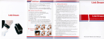
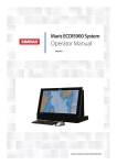
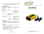
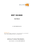
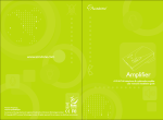
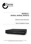
VDS4020
Active IP over Coax extended kit
User Manual
1. Key Features
•
•
•
•
•
•
•
It is applicable to all kinds of IP cameras.
One cable transmits all signals and DC power.
Downlink data throughput (from camera to receiver) of up to 28 Mbit/s.
Uplink data throughput of up to 4 Mbit/s.
Built-in electrical transient voltage suppressor (TVS) and gas tube arrester (GTA) protection on LINK IN / LINK
OUT ends.
Supports P/T/Z (pan, tilt, zoom) cameras.
Up to 800 meters range with DC power transmission.
2. Technical Specification
Model Number
VDS4020
SPECIFCATION OF VDS4020-R SENDER
Ethernet
10/100Mbps Ethernet standard
Link Signal: Downlink 18MHz (output signal)
Link OUT/IN with DC IN
Downlink Signal Bandwidth: 8.5MHz
DC IN: +28V to +48V
Downlink Throughput
28Mbps
Power Output
PoE Power, DC 48V,15.4W, Meets IEEE802.3af, class 0 (include 1-4)
Unit Dimensions
(L x W x H): 84mm x 50mm x 25mm
Weight
135 grams
Operating Temperature
-10 to 50°C (14 to 122°F)
Relative Humidity
20% to 90%, noncondensing
Specification of VDS4020-L Viewer
Ethernet
10/100Mbps Ethernet standard
Link Signal: Uplink 39MHz (output signal)
Link OUT/IN with DC OUT
Uplink Signal Bandwidth: 2.5MHz
DC OUT: +47V
Uplink Throughput
4Mbps
DC Power Input
DC 48V ± 8%, 1.25Amps max
Unit Dimensions
(L x W x H): 84mm x 50mm x 25mm
Weight
98 grams
Operating Temperature
-10 to 40°C (14 to 104°F)
Relative Humidity
20% to 90%, noncondensing
*Design and Specifications are subject to change without notice.
2
CHANGE THIS TO WHAT THE PRODUCT IS AND COPY INTO THE MASTER PAGE A
Current IP camera security system installation uses standard Cat-6 as the link cable, transmiting only up to 100
meters far. Now our VDS4020 offers a more convenient and reliable solution for IP Network cameras. It transmits
IP signals up to 800 meters to the Local side and also supplies DC power simply through one coaxial cable and
PoE powering IP camera, PoE can be achieved SNMP management capabilities.
1. Look upon VDS4020-R (Sender) as PSE and IP cameras as PD.
2. PoE integrates data and power on the same wires
3. Simplified installation work, saves time and money.
4. Complies with IEEE802.3af, class 0 (include 1-4)
Fig. 1 VDS4020 RU / LU, and Power Adaptor
Introduction
The VDS4020 is a pair consisting of a Remote Unit and a Local Unit connected via coaxial cable (RG-6/U, 5C-2V or
equivalents). The Remote Unit (RU; the “Transmitter"; the Sender) is placed at the IP camera end, and the Local
Unit (LU; the "Receiver"; the Viewer) is placed at the NVR/DVR end. The downlink IP packets (typically compressed
video data) from the camera are modulated at the RU and transmitted"downstream" to the LU over the COAX
connection. The uplink IP packets (PTZ control signals, etc.) from the NVR/DVR are modulated at the LU and transmitted "upstream" to the RU through the COAX.
The coaxial cable that sends IP packets upstream or downstream also serves as a path to supply power. The LU
accepts 48V DC power, which will be sent to the RU through COAX after passing the safe power transmission
controller. The RU then converts the power to the voltage that cameras use.
Safe power transmission is a very important function. The safe power transmission controller checks 48V DC first.
The power will be transmitted only after the LU and the RU are confirmed to be correctly connected. Thus, it prevents any danger caused by the misconnection of the coaxial cable.
Be sure to use the coaxial cable with the impedance of 75 ohms. COAX of RG-6/U, 5C-2V or equivalents is recommended. Please avoid using RG-59/U because its core is copper clad steel, which has great DC resistance and
affects the DC power transmission. For long distance transmission, RG-11/U or 7C-2V is a great alternative. The
low DC resistance of either COAX reduces the consumption and makes it possible to transmit the power over
1,000 meters.
Connection Diagram
The following illustration gives an
overview of how the Sender and
the
Viewer connect. Please note that
the coaxial cable should always be
connected to the LINK OUT side of
the Sender.
CHANGE THIS TO WHAT THE PRODUCT IS AND COPY INTO THE MASTER PAGE A
3
Overall Certificate
This equipment has been tested and found to comply with Part 15 rules of the US FCC Regulation. Also, it gets CE
approved and complies with European Directive 2004/108/EC - Restriction of Hazardous Substance (RoHS).
Limited Warranty
Genie grants a warranty of this product for 18 months. Please offer the purchase date and the serial number of
the Bar-code on the back of the product to your distributor or retailer as a proof for this purpose. During
the warranty period, in case of defects in material or workmanship, thedefective unit will be repaired or replaced
according to the assessment of Genie.
However, this warranty does not cover damages caused byimproper use nor from unauthorized modifications by
third parties.
Patents
The patents that cover design, operation, techniques, and unique features of a single-cable transmission device
for a surveillance system are still pending.
System Description
The RU and the LU are to be installed in different locations. In addition, the RU is required to offer a huge amount
of power. So please refer to pages 4 and 5 for their different operating temperatures. The ambient
storage temperature is from -30°C to 75°C and the relative humidity is from 20% to 90%. Remember that both the
RU and the LU need to be kept somewhere well ventilated.
Please be informed that the allowable maximum DC resistance of the coaxial cable between the Sender Unit and
the Viewer Unit varies with the difference of current and voltage consumption of the camera. Please see
the table below for more information.
Further Description of VDS4020
• Designed for surveillance IP cameras for long distance transmission.
• Transmits IP duplex signals up to 800 meters away and sends PoE power to the cameras through a coaxial
cable as opposed to Ethernet UTP Cat6 cable which transfers signals for only 100 meters.
• Applies to all low and high resolution IP cameras, including PTZ cameras and infrared cameras with high
power consumption.
Safety Features:
1. Powers camera only after local unit and remote unit are connected correctly.
2. Auto shutdown for short circuit, open circuit, and overloads.*
3. Auto test and reconnection until the problem is solved.
4. Built-in TVS and GDT against lightning-induced current and transient voltage.
*Safe Power Transmission
Remote modules are tested before the system sends power. When coaxial cable linked between the VDS4000
system has a short circuit or open circuit, the power supply is cut off immediately which shuts down the system
to protect the system and the related camera equipment. The Viewer then activates the auto detection
function, which tests the connection repeatedly. After the connection goes back to normal, the system will reactivate the power supply.
The Local side detects the connection status every 2.5 seconds until the disconnection problem is solved.
The system will shut down if any of the following situations occur:
1. Open circuit—System shuts down after open circuit of the coaxial cable lasts more than 0.5 seconds.
2. Short circuit—System shuts down within 10 micro-seconds after short circuit. When a short circuit happens, the system detects that the voltage value of the Link IN with DC OUT drops below 70% and then cuts off power to the control MOS-FET switch. This interval is within 10 micro-seconds.
3. Over loaded—System shuts down when the power is overloadedmore than 10%.
If any of the above circumstances happen, the system will automatically try to reconnect recurringly. Once the
condition is solved, the system will reconnect and supply power again. solved, the system will reconnect and
supply power again.
4
CHANGE THIS TO WHAT THE PRODUCT IS AND COPY INTO THE MASTER PAGE A
Connection Diagram
The following illustration gives an overview of how the Sender and the Viewer connect. Please note that the coaxial cable should always be connected to the LINK OUT side of the Sender.
CHANGE THIS TO WHAT THE PRODUCT IS AND COPY INTO THE MASTER PAGE A
5
Installation of Remote and Local Units
The VDS4020 units can both be fixed to the wall or the desktop with the
supplied mounting brackets. The mounting brackets can be fixed onto the
rear, top, or bottom of either unit.
Attaching the Mounting Brackets
Attach the mounting brackets to either the Sender Unit or the Viewer Unit as shown
below:
1. Align the mounting bracket with the mounting track.
2. Slide the bracket until the white nub clicks into place and locks the unit to the mount.
3. Repeat the same steps for the second bracket.
4. Fasten the unit in the desired location with two screws.
Removing the Mounting Brackets
Use a flat-tipped screwdriver to lift the white nub to remove the brackets.
6
CHANGE THIS TO WHAT THE PRODUCT IS AND COPY INTO THE MASTER PAGE A
Power Supply Adaptor and Appearance
With a power capacity of 60 watts, the Power Supply PD4860 provides enough power for the whole VDS4020
system and the camera on the remote side.
Besides, it compensates for the power consumption caused by the DC resistance through the coaxial cable during power transmission.
Two holding brackets and six screws come with the purchase of the power adaptor, which could be inserted into
the brackets and fastened to the desired location. For users who do not purchase the power adaptor from Biwave,
48V DC (the standard industrial voltage) power adaptor could be used. It could be obtained
from either the industrial DC power supply or Din Rail DC power supply. Just remember to add a 5.0mm spacing
plug (pluggable terminal block) to the Viewer as shown in the drawing.
Supplier Part Number: GS60A48
Electric Specifications:
AC Input: 100 ~ 240V AC
Output: 48V DC, 1.25 Amps
Power Rating: 60 watts
Physical Specifications:
Weight: 270 grams
Weight with two holding
brackets: 306 grams
Environmental Specifications:
Operating Temperature: 0 to 45°C (32 to 113°F)
Relative Humidity: 20 to 90 percent, noncondensing
Storage Temperature: -45 to 85°C (-49 to 185°F)
Fig 6. Installation of Power Supply Adaptor
CHANGE THIS TO WHAT THE PRODUCT IS AND COPY INTO THE MASTER PAGE A
7
Use Correct Coaxial Cable
Coaxial cable is the transmission medium we use for our VDS devices. Varieties of Coax could be found, but users
should always avoid using coax whose inner conductor is made of copper clad steel. Steel has greater DC resistance, which lowers power transmission capability. Table 2 shows the general specifications of the RG-6/U coaxial
cable that we normally recommend. Remember that the total value of DC resistance is the sum of DC resistance
from both the inner and outer conductors.
Table 2. General Specifications of the RG-6/U Coax
Packing Checklist
Carefully unpack the packing box of the VDS4020 and check if the following items are included:
•
•
•
•
•
•
VDS4020-R Sender (Remote Unit)
VDS4020-L Viewer (Local Unit)
A power supply unit (an AC to DC power adaptor) and a power cord
Four mounting brackets for the unit, two holding brackets for the poweradaptor, six screws and six nylon
anchors
1 foot cat-6 network patch cable with molded RJ-45 boot
Installation Guide
Contact your dealer immediately if any of the above items appears damaged or the unit does not work.
8
CHANGE THIS TO WHAT THE PRODUCT IS AND COPY INTO THE MASTER PAGE A
GENIE CCTV LTD.
CCTV House, City Park, Watchmead, Welwyn Garden City, Hertfordshire, AL7 ILT
Tel: +44 (0) 1707 330541 Fax: +44 (0) 1707 330543
www.geniecctv.com
Edition. GN-February 2015