1
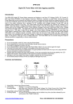
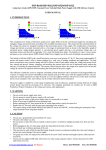
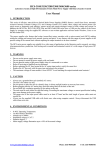
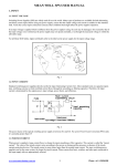
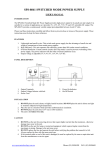
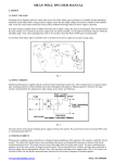
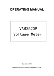
DPM-3221
Digital DC Power Meter with Data logging capability
User Manual
Introduction
The DPM-3221 digital DC Power Meter measures and displays in real time; DC Voltage (0-60V), DC Current (0200A with a 200A/50mV* external shunt) and Watts (0-12000W). It also displays; Amp-hour, Watt-hour, maximum or
peak Watts, running time since Power Meter start up and minimum and maximum values of voltage and current
during the measuring period. The power for the meter can either be from the source or the load whichever has a
minimum 5V DC available (only voltages between 5V and 60V can be measured when powered in this way). The
Power Meter can also be powered by an external DC voltage of 5 to 60VDC, which then allows a voltage
measurement range of 0-60V. Once the Power Meter is powered up it starts to display and log the Voltage and
Current. It also displays Wattage, Amp-hours, Watt-hours, Max. & Min. Voltage and Current and peak Watts. The
logged data values are recorded at 3 minute intervals. Up to 1,500 sets of data can be stored in the Power Meter’s
Memory (EEPROM) so even when the Power Meter is powered down, data is retained. The data can be retrieved
by a PC using the optional Data Adapter (DPA-3051) and a software program provided. Unless reset, the last set
of data values; Ah, Wh, peak Current, peak W atts, (and sometimes min. and peak Voltage), is retained and
displayed when the DM-3221 is powered up. A new group of data (up to 20) is created each time. The Power Meter
can be mounted using the Snap-On bracket provided or magnetically on ferrous metal surfaces. *50A/50mV and
100A/50mV shunts may also be used with current ranges of 0-50A and 0-100A respectively.
Precautions
a.
b.
c.
d.
e.
f.
Do not exceed 60A or 60V DC when using the Power Meter.
Do not apply 60A for more than 5 seconds within any 60 second interval.
This meter is designed for indoor use only.
Do not disassemble or attempt to repair the Power Meter. Return it to your service agent for repair.
If the start-up screen does not appear, immediately remove the power source.
Do not short-circuit the input or output leads. It is good practice to have both the input and output terminal
blocks connected to prevent short circuits.
g. Double check the correct input and output polarity. If the input connection has the wrong polarity, the LCD
display will not show. Wrong polarity on the output may result in excessive current flow.
h. Damage to the Power Meter may result if voltage is applied with the wrong polarity.
i. Do not exert pressure directly on the LCD display as damage may occur.
Controls and Indicators
FRONT
1. Shunt connector
2. LCD Display
Scrolling display
3. Scrolling display
: Flat cable with phone plug RJ12 6P/4C.
: Displays: V, A, and W continuously.
: Amp Hour (Ah), Watt Hour (Wh), Peak Voltage (Vp), Peak Current (Ap), Peak Watts
(Wp), Min. Voltage (Vm) or sag, Min. Current (Am) and total time since power up.
: Any one of the scrolling displays can be halted at any time (and also released) by one
quick press of the "Reset" button (5)
www.procontechnology.com.au
Phone: (03) 98306288 FAX: (03) 98306481
SIDE
3. External Power Socket:
An external power source (5-60VDC) extends the measured voltage range from 5-60V to 0-60V.
Pins: 5V-GND-RC
5V = +5V to +60V external DC source.
GND = Ground or negative of external DC source.
RC = Remote Clear, this is for deleting the stored data and setting the shunt rating.
4. Phono Socket: for connection to optional Data Adapter (DPA-3051).
5. Reset Switch: To clear saved data and to setup the unit and halt/continue display scrolling.
Connector
PIN
1
2
3
4
5
6
www.procontechnology.com.au
Function
CC+
NC
NC
V+
GND
Description
SENSOR SENSOR +
No Connection
No Connection
Voltage +
Voltage -
Wire Colour
Silver
Yellow
Green
Brown
Black
Blue
Phone: (03) 98306288 FAX: (03) 98306481
Wiring Diagram
Optional external DC supply
required if Source 0-60V.
Operation and Display Screens:
Installation of the DC Power Meter:
1. First connect a DC source to the meter and check that the DPM powers up. If no display appears then
check for reverse polarity and ensure that the voltage is greater than 5 Volts.
2. The last set of accumulated data will appear on the LCD. The old data can be cleared by pressing the
Reset Button for 5 seconds twice. See the “Resetting the DPM-3221” section for more information.
3. Connect the remaining leads to complete the installation of the DC Power Meter.
www.procontechnology.com.au
Phone: (03) 98306288 FAX: (03) 98306481
DISPLAYS:
A. On first powering up the display, the firmware version and factory preset data port mode are shown. Then
it briefly shows the preset shunt rating of the DPM and finally the data display appears.
B. On the data display, the Volts, Amp and Watt are continuously displayed; all other data is shown
cyclically at about 3 second intervals. The display can be toggled bet ween fixed and cyclical by one
quick press of the "Reset" button (5).
1. Current (Amps - A, Peak Amps - Ap, Minimum Amps - Am):
The Amps value is the average current through the Meter's black wire over the last screen update
interval. Ap is the Peak (maximum) current to the LOAD, since start up to the present time.
Similarly, Am is the minimum current.
2. Voltage (Volts - V, Maximum Voltage – Vp, Minimum Voltage - Vm):
The Volts value is the average voltage over the last screen update interval. Vp is the Peak (maximum)
voltage from the source side since start up to the present time. Similarly for Vm (minimum) which is the
minimum voltage, voltage dip or sag on the source side since start up.
3. Charge (Amp-hours - Ah):
The value displayed is the total charge in Amp-hours delivered to the LOAD since start up. The Amphours is determined using the internal clock of the MCU.
4. Energy (Watt-hours - Wh):
The value displayed is the total energy delivered to the LOAD in Watt-hours since start up. The Watthours is determined using the internal clock of the MCU.
5. Power (Watts - W, Peak Watts - Wp):
The value displayed is the average power delivered in Meter over the last screen update interval. The
displayed Peak Watts value (Wp) is the maximum power drawn of the LOAD, since start up.
C. Operation time since start up:
The second line displays the elapsed time since start up in HH:MM:SS format.
www.procontechnology.com.au
Phone: (03) 98306288 FAX: (03) 98306481
Setting the Shunt rating of the DPM
If you want to change the DPM shunt rating to match your shunt, proceed as follows:
1. After checking the DPM is in good order, power down the unit – if necessary, unplug the phone jack from
the interconnector.
2. Plug in the supplied external power plug into the 5V-GND-RC socket. A 9V battery connected to the
positive (red) wire and negative (black) wire is best to power the unit whilst the shunt rating is being set.
3. Power up the unit and when the “External Shunt” is displayed, press and hold the reset button for 3
seconds.
4. Release the reset button and note that the LCD will show the current DPM shunt setting. Fig. 1.
5. A quick press on the Reset Button will cycle the shunt setting from 100A to 200 A. Press again for 50A
and again to go back to 100A. Fig. 1, 2 and 3. Select the required shunt setting in this way.
6. Make a quick connection of the black (GND) and white (RC) wires to confirm the currently displayed
shunt setting and the LCD will then show the normal data display. Fig. 4.
7. Power down the unit and power up again and verify that the “External Shunt” is set correctly.
8. Plug the phone jack into the new shunt and check that the readings are correct.
www.procontechnology.com.au
Phone: (03) 98306288 FAX: (03) 98306481
Resetting the DPM-3221
There are two ways to clear the previously stored data.
1. Press and hold the Reset button (5) until the LCD display indicates “Press again 5 seconds to
reset”, then release the Reset button and press again holding for 5 seconds to delete the data.
2. Use the external power source socket and connect the remote I/O (white wire) as shown below. This is
marked RC on the s i d e o f t h e DPM to t h e G N D o r negative terminal (black wire) for 3 seconds.
All previously recorded data is then erased.
www.procontechnology.com.au
Phone: (03) 98306288 FAX: (03) 98306481
SPECIFICATIONS
Model
Measured Parameters
Current Range Amp (A)
Voltage Range Volt (V)
DPM-3221 (For use with external shunt)
50A/50mV
100A/50mV
0-50A cont.
0-100A cont.
Accumulative Max. Operation
Period logged
75 hours (3 min. data logging interval, 1500 samples)
Scrolling speed on LCD
Data logging interval
Operation Voltage and Current
External DC Source Range
Operation Condition
Storage Condition
Construction
LCD Display
Housing Material
Dimension & Weight
3 seconds for one parameter
3 minute
5-60V, 12mA
5-60V, 8mA-12mA
0°C to 50°C, non-condensing humidity
-10°C to 60°C
200A/50mV
0-200A cont.
5-60V or 0-60V with external DC source
Max. recorded W:12,000W
Power Watt (W)
Resolution of W:0.1W for W<10,000
1W for W>10,000
Resolution of V&I
0.01V,0.01A
0.01V,0.02A
0.01V,0.05A
Scrolling Display of Registered Parameters:
Max. recorded Ah: 99,999Ah
Resolution of Ah: 0.01Ah for total recorded Ah <1,000Ah
Ampere Hour (Ah)
0.1Ah for 10,000 > total recorded Ah > 1,000Ah
1Ah for total recorded Ah > 10,000Ah
Peak Watt (Wp) registered
Max. recorded W: 12,000W
Resolution of W: 0.1W
Energy: Kilo Watt Hour (kWh)
Max. recorded kWh: 9999.9kWh
Resolution of kWh: 0.1kWh
Registered Peak Voltage(Vp),
The new high and low values of voltage and current will
Min.Voltage(Vm), Peak Current(Ap), replace the old ones during the metering period and
Min. Current(Am), Peak Watt(Wp)
registered at the end of the metering period
Supplied Accessories
Optional Accessories
Approvals
VA = 54mm x 14.4mm, 16 character x 2 row STN 5*8 dots
Polycarbonate
75(L) x 45(W) x 23(D) mm
100g approx.
User manual, snap-on mount & external power cable with plug,
phone cable with RJ-12 6P/4C plug, inline RJ-12 coupling.
1. Data adapter module and software for data logging.
2. External DC power box with plug.
3. External shunt modules with 5m phone cable and RJ-12
6P/4C plug.
CE EN 61326 , FCC
REV.2
www.procontechnology.com.au
2015/01
Phone: (03) 98306288 FAX: (03) 98306481