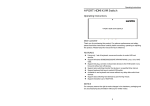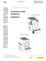
1
M-WRG-S M-WRG-K Installation manual HOME VENTILATION WITH HEAT RECOVERY Ventilation Units M-WRG-K Flush-mount Installation M-WRG-S Surface-mount Installation Order Nr. 5300-10-01 06/2011 1 Meltem Wärmerückgewinnung GmbH & Co.KG Am Hartholz 4 D-82239 Alling [email protected] www.meltem.com M-WRG-K M-WRG-S Installation manual Important user information Ventilation with heat recovery With the decentralized ventilation system M-WRG with heat recovery from Meltem you have acquired a high quality product. This ventilation system serves you as an improvement for your home and your health as well as a protective measure against moisture and mold damages in your home. Ventilation by opening windows, especially during cold seasons, belongs to the past. From now on, fresh and filtered air is supplied fully automated. The stale air is extracted and its warmth transferred to the fresh air, via the heat exchanger. While doing so, the M-WRG ventilation units have minimum power consumption. You save heating costs, increase the comfort of your home and at the same time reduce the impact on the environment by reducing CO2 emissions. Of course you still may open your windows especially during warmer days. A family of four produces daily an average of 10-14 liters of moisture, due to cooking, laundry, personal hygiene, and breathing of inhabitants, plants and animals! This excessive amount of moisture, within the interior air, is extracted through the M-WRG ventilation unit and therefore prevents the forming of mold and resulting damages in the building structure. At the same time, fumes from floors, furniture and a too high CO2 concentration in the air, which can lead to fatigue and health issues, will be extracted from the interior rooms and replaced by fresh and clean air. Please read this manual carefully and follow the instructions contained in this manual. Additionally, familiarize yourself with the operations of the M-WRG ventilation unit, as well as please pay attention to the warnings and cautions contained in this manual. The M-WRG ventilation unit may only be operated once installed correctly. • When ventilating basements or similar rooms we advise to be cautious (especially during the summer season and warm weather), due to the fact that the moisture in the air will condense on cold interior walls and - despite ventilation moisture damages can occur. Therefore, please only ventilate at night during warm weather seasons! If you would like to ventilate such rooms with an M-WRG ventilation system, please consult with the manufacturer prior to purchase. Am Hartholz 4 D-82239 Alling [email protected] www.meltem.com The M-WRG ventilation unit has been designed for continuous operation and a long lifespan. During cold seasons, the M-WRG ventilation unit should be operated continuously. The energy saving motors and innovative electronics guarantee – despite continuous operation- for a low power consumption (approx. 3.8 Watt at level 1). Only a continuous operation achieves a permanent extraction of moisture and condensation. If this does not occur, it is possible that condensate will gather in the unit. • If a high concentration of moisture occurs, we recommend regularly ventilating the room at the highest ventilation level for 10 minutes, in order to eliminate any possible condensation inside the unit. • In order to guarantee a smooth operation, especially during low exterior temperatures (below -5°C), you should avoid interior temperatures below 15°C. The unit automatically monitors the filter status. An acoustic warning signal will inform you, when the filters need to be replaced. However, for hygienic reasons, it is strongly recommended to replace the filters at least once per year, ideally before the heating season. For a reliable operation of the units and for your own safety, only original and certified parts from Meltem should be used. Otherwise this may void the warranty and Meltem will not be liable for any damages. We hope you will enjoy your new M-WRG home ventilation system with heat recovery! 2 Meltem Wärmerückgewinnung GmbH & Co.KG • Maintenance and Filter replacement Never operate the M-WRG ventilation unit without filters. Only with the original filters from Meltem, the units will remain clean, fully operative, and have a long lifespan. • Never cover the M-WRG ventilation unit or any part of it with e.g. cabinets, blinds or curtains. A minimum distance of 30 cm to any furniture is required, in order for the M-WRG ventilation unit to remain fully operable. Caution: In case of exterior temperatures below 0°C, icicles may form at the façade covers. These should be removed for safety purposes. Directions for correct usage • • M-WRG-K M-WRG-S Installation manual Contents 1. Safety instructions ............................................................................................................................................ 4 1.1. Assemble only with correct mounting elements ................................................................................................. 5 1.2. Safety precautions during installation/connecting to electricity ........................................................................ 5 1.3. Vapor barrier ....................................................................................................................................................... 5 1.4. Warning: Operation with open fire places .......................................................................................................... 5 1.5. Warranty ............................................................................................................................................................. 5 2. Materials ........................................................................................................................................................... 6 2.1. M-‐WRG-‐S packaging contents ............................................................................................................................. 6 2.2. M-‐WRG-‐K packaging contents ............................................................................................................................. 6 2.3. Optional installation material .............................................................................................................................. 6 3. Preparations for the surface-‐mount installation (AP) ......................................................................................... 7 3.1. General information ............................................................................................................................................ 7 3.2. Choose a location for the surface-‐mount installation ......................................................................................... 7 3.3. Dimensions .......................................................................................................................................................... 8 3.4. Determine installation location with the drilling template ................................................................................. 8 3.5. Cut a channel for the power cord ........................................................................................................................ 9 3.6. Drilling ................................................................................................................................................................. 9 3.7. Insert ventilation pipes ........................................................................................................................................ 9 3.8. Install the power cord ....................................................................................................................................... 10 3.9. Resurfacing ........................................................................................................................................................ 10 3.10. Cut ventilation pipes ....................................................................................................................................... 10 4. Preparations for the flush-‐mount installation (UP) .......................................................................................... 11 4.1. Prepare mounting box ....................................................................................................................................... 11 4.2. Insert ventilation pipes ...................................................................................................................................... 11 5. Install M-‐WRG ventilation unit ......................................................................................................................... 12 5.4. Remove cover for electrical connectors ............................................................................................................ 13 5.5. Install casing ...................................................................................................................................................... 13 5.6. Connect M-‐WRG ventilation unit ...................................................................................................................... 13 5.7. Put electrical connector cover back on ............................................................................................................. 14 5.8. Close unit cover ................................................................................................................................................. 14 6. Install masking frame ....................................................................................................................................... 15 7. Install façade cover .......................................................................................................................................... 15 8. Start up the ventilation unit ............................................................................................................................. 15 3 Meltem Wärmerückgewinnung GmbH & Co.KG Am Hartholz 4 D-82239 Alling [email protected] www.meltem.com M-WRG-K M-WRG-S Installation manual 1. Safety instructions • The M-WRG ventilation unit may only be operated once installed correctly. • For correct installation of the system please follow the instructions of the assembly manual. • The M-WRG ventilation unit may only be used for the ventilation of living space and interior rooms (Kitchens, bathrooms, basements, offices, etc). With rooms that have an excessive build up of dust and/or corrosive gas emissions, the M-WRG ventilation unit may be limited and/or damaged in its operating capacity. • Please familiarize yourself with the operating modes and procedures of the M-WRG ventilation unit. • The M-WRG ventilation unit is especially suitable for the drying phase after a building is constructed and the inhabitants have moved in. It is not suitable for drying a building during construction or to ventilate a building while interior renovations are in progress. A continuously high concentration of dust and/or moisture will clog the filters additionally and overwork the automated extraction of condensate. • Never operate the M-WRG ventilation unit without the suitable filters. The filters protect your health and living space from exterior environmental influences. Only with the suitable filters, the M-WRG ventilation unit will remain clean. Additionally it will prevent the pollution of the electrical components and the heat converter, as well as reduce or prevent full operating capacity of the M-WRG ventilation unit. • Do not install the M-WRG ventilation unit into the interior of a cabinet or other furniture. Do not cover the MWRG ventilation unit with any type of fabric (towel, curtains, etc.) or any other objects (furniture, blinds, etc.). • Please follow the instructions contained in this user manual. • Please follow the maintenance instructions contained in this user manual. • Observe the VDE safety regulations, all national regulations in the country of use as well as the connection and safety regulations of the local energy supplier. • Important Indication according to DIN EN 60335: This M-WRG ventilation unit is not to be operated by persons (including children) with limited physical, sensory or mental capabilities, or lack of experience and/or lack of knowledge. Except if they are supervised, or were given instructions how to use the M-WRG ventilation unit by a legal guardian, responsible for their safety. Children should be supervised, in order to ensure that they are not playing with the M-WRG ventilation unit. • If these Safety instructions are not regarded, Meltem will not be held liable! Safety Warning for installing the M-WRG ventilation unit in rooms with open fire places: During the planning and installation process of the ventilation system, the fireplace safety regulations (i.e.FeuVo) and civil building codes have to be met! Additional safety equipment may have to be installed. Before operating the M-WRG ventilation unit, the installation has to be discussed and approved by the responsible official authorities and the chimney sweeper. Safety Warning: Build up of icicles: In case of exterior temperatures below 0°C, icicles may form at the façade covers. This is not a malfunction of the ventilation units. The installation site of the units has to be selected in such a way, that in case of breaking and falling icicles no persons or objects are damaged. 4 Meltem Wärmerückgewinnung GmbH & Co.KG Am Hartholz 4 D-82239 Alling [email protected] www.meltem.com M-WRG-S M-WRG-K Installation manual 1.1. Assemble only with correct mounting elements The mounting elements, which are included in the delivery, are to be installed on the exterior wall. Only use certified mounting parts from the manufacturer! 1.2. Safety precautions during installation • • • • Electrical connections may only be carried out by certified technicians. Please pay attention to the safety precautions while working with power tools. Please pay attention to the safety precautions while installing the mounting elements. Ensure that the working area is secured in case of falling parts. Ensure that there are no power lines running through the wall you plan to install the mounting elements. 1.3. Vapor barrier In case you are installing the ventilation unit in a wall with a vapor barrier, the vapor barrier has to be properly resealed as required by the manufacturer. 1.4. Warning: Operation with open fire places During the planning and installation process of the ventilation system, the fireplace safety regulations (i.e.FeuVo) have to be met! Before operating the M-WRG ventilation unit, the installation has to be discussed and approved by the responsible official authorities and the chimney sweeper.The M-WRG ventilation units are only allowed to be installed in living environments with open fireplaces, if: 1. 2. A simultaneous operation of open fireplaces that use liquid or gaseous fuel and the ventilation unit M-WRG is prevented by safety equipment, or The exhaust air of an open fireplace is monitored by safety equipment. In case the safety equipment is triggered, the open fireplace or the M-WRG ventilation unit has to be turned off. The M-WRG installation units are not to be installed, if the open fireplace is connected to a flue gas system with multiple connections. In order to operate the M-WRG ventilation units in accordance with regulations, exhaust air conducts of open fireplaces have to able to be turned off by a shutoff device. In case of open fireplaces that use solid fuel, the shutoff device has to be manually operable. The position of the shutoff device’s lever has to be clearly labeled, indicated and recognizable. 1.5. Warranty Improper installation invalidates the warranty. No warranty is offered for the installation and the correct implementation of the installation. 5 Meltem Wärmerückgewinnung GmbH & Co.KG Am Hartholz 4 D-82239 Alling [email protected] www.meltem.com M-WRG-S M-WRG-K Installation manual 2. Materials • Façade cover e.g. M-WRG-ES (Model.Nr.5150) 2.1. M-WRG-S packaging contents • Drilling template for façade cover M-WRG-ES (Model.Nr.5327) Ventilation unit with heat recovery • 1 M-WRG ventilation unit 2 ventilation pipes DN100 • 4 flat washers • 4 screws for the surface-mount installation Ø5x120mm • 4 screws for the flush-mount installation Ø5x100mm • 4 centering gauges • 4 dowels Ø8mm • 1 User manual • 1 Installation manual 2.2. M-WRG-K packaging contents Ventilation unit with heat recovery, comfort edition • 1 M-WRG ventilation unit • Remote control • 2 ventilation pipes DN100 • 4 flat washers • 4 screws for the surface- mount installation Ø5x120mm • 4 screws for the flush- mount installation Ø5x100mm • 4 centering gauges • 4 dowels Ø8mm • 1 User manual • 1 Installation manual 2.3. Optional installation material Not included in the packaging • Drilling template M-WRG-BS (Model.Nr.5322) 6 Meltem Wärmerückgewinnung GmbH & Co.KG Am Hartholz 4 D-82239 Alling [email protected] www.meltem.com M-WRG-S M-WRG-K Installation manual 3. Preparations for the surface-mount installation (AP) 3.1. General information The wall where you wish to install the unit has to be even. Surface irregularities will warp the casing of the unit and therefore can affect the functionality of the unit. For power supply 230V AC is needed. The unit may be connected using a 3x1,5 mm² or NYM 2x1,5 mm² cable 3.2. Choose a location for the surface-mount installation The unit has to be installed on the inside of an upright exterior wall. The ideal exchange of air and heat recovery is reached if the unit is installed 300mm below the ceiling. (A minimum distance of 150mm to the ceiling is required! ) It is also necessary that the unit has a distance of minimum 50mm to adjacent objects or surfaces. • Furnishing: After the M-WRG ventilation unit has been installed, please note that the unit may not be covered or obstructed by furniture, curtains or other items. • Utility and power lines: Please ensure that there are no utility or power lines of any kind running through the installation area • Build up of icicles: The ventilation unit automatically discharges any condensate to the exterior. This may lead to icicles during the winter season, which might fall down and cause damage.. This has to be taken into consideration when choosing the installation site for the unit! • Installation in bathrooms: Observe civil building codes (e.g. VDE 0100) to ensure a minimum clearance to water taps, bath tubs, faucets ect. • Open fireplaces: See Chapter 1.4 7 Meltem Wärmerückgewinnung GmbH & Co.KG Am Hartholz 4 D-82239 Alling [email protected] www.meltem.com M-WRG-S M-WRG-K Installation manual 3.3. Dimensions All dimensions are in mm • 3.4. Determine installation location with the drilling template • With the aid of a level, mark a horizontal line on the wall. This will mark where the top edge of the unit will be. There should be a 300mm distance in between the line and the ceiling. (minimum 150mm) • Align the top of the drilling template on the line and fixate it with tape. • With the aid of the level reassure that the drilling template is still straight • Mark along the contours of the drilling templates • Remove the drilling template 8 Meltem Wärmerückgewinnung GmbH & Co.KG Am Hartholz 4 D-82239 Alling [email protected] www.meltem.com Mark a hairline cross M-WRG-S M-WRG-K Installation manual 3.5. Cut a cable duct for the power cable • Mark a line for the power cord channel (indicated on the drilling template). The exact location of the power cord channel needs to be determined on site. • Cut out the cable duct. • For the units M-WRG-S/Z-A, M-WRG-S/Z-EIB M-WRG-S/Z-24, M-WRG-S 458 M-WRG-S 458-TF, M-WRG-S 458-TFC a control cable is needed in addition. Mark the control cable and the cut the duct out. 3.6. Drilling • Drill 2 holes (Ø 120mm) with a cored hole drill along the marked points. Keep a 2° downward gradient angle. • Drill 4 holes for the dowels along the marked points. Ø8mm, 60mm deep 3.7. Insert ventilation pipes • Level and fixate the drilling template along the hairline cross, and hold it in place by inserting the 8mm dowels. • Insert both pipes through the drilling template into the holes. With the aid of the drilling template, position the ventilation pipes correctly and fixate them (interior wall). • Fill the hollow space in between the pipe and the wall with expanding foam. • Remove the drilling template and push the dowells in, until they line up with the wall 9 Meltem Wärmerückgewinnung GmbH & Co.KG Am Hartholz 4 D-82239 Alling [email protected] www.meltem.com M-WRG-K M-WRG-S Installation manual 3.8. Install the power cable • • Install a power cable, size 3x1,5 mm² or NYM, excess length of aprox.250mm With the units M-WRG-S/Z-A, M-WRG-S/Z-EIB, M-WRG-S/Z-24 , M-WRG-S 485, M-WRG-S 485-TF, M-WRG-S 485-TFC an additional control cable needs to be installed. excess length of aprox.250mm 3.9. Resurfacing • • • Caution! Before resurfacing, ensure that the ventilation pipes are covered! Resurface and reseal the wall Wait for plaster to dry 3.10. Trim ventilation pipes • • • Cut the ventilation pipes on the inside so they are level with the wall Smooth out any rough edges, deburr Cut and deburr the ventilation pipes on the outside depending on the façade covers: Facade cover model Excess length of ventilation pipes Ventilation hood M-WRG-ES Ventilation Grille-Set M-WRG-ESR Ventilation Grille (AP) M-WRG-ESG/AP 5-10mm 25-30mm 5mm 10 Meltem Wärmerückgewinnung GmbH & Co.KG Am Hartholz 4 D-82239 Alling [email protected] www.meltem.com M-WRG-K M-WRG-S Installation manual Ventilation Grille (UP) M-WRG-ESG/UP Please contact manufacturer of facade 4. Preparations for the flush-mount installation (UP) 4.1. Prepare mounting box Check if the mounting box has been installed correctly according to installation manual M-WRG-M Art.Nr. 5300-00-01, or M-WRG-MB Art.Nr. 5300-01-01: • Remove the red protective cap • Remove the plaster protective cover. • Remove plugs from the openings for the ventilation pipes • If needed clean the mounting box 4.2. Insert ventilation pipes • Insert both ventilation pipes into the mounting box until they are flush mounted • Mark the length of the ventilation pipes on the exterior side depending on the façade cover Facade cover model Excess length of ventilation pipes Ventilation hood M-WRG-ES 5-10mm Ventilation Grille-Set M-WRG-ESR 25-30mm Ventilation Grille (AP) M-WRG-ESG/AP 5mm Ventilation Grille (UP) M-WRG-ESG/UP: Please contact manufacturer of facade • Remove ventilation pipes and cut them to the correct length. Smooth out any rough edges • Insert both ventilation pipes into the mounting box until they are flush mounted and fixate them with silicone 11 M-WRG-K M-WRG-S • Installation manual Seal the ventilation pipes on the outside with silicone 5. Install M-WRG ventilation unit The following steps are identical for the installation of flush- and surface mount! 5.1 Remove unit cover • With both thumbs, press down the two hooks on the bottom of the M-WRG ventilation unit and at the same time grab the edge of the cover with both index fingers and then carefully lift the cover up and towards you. 5.2 Seal the stubs • Check the sealing tape, make sure it goes all the way around the stub 5.3 Insert mounting screws • Put flat washers onto the screws, then insert the mounting screws through the holes • Push the centering gauges onto the screws so the tip of the screws stick out about 1cm • Surface-mount: Use Ø5x120mm mounting screws • Flush-mount: Use Ø5x100mm mounting screws 12 M-WRG-K M-WRG-S Installation manual 5.4. Remove covers for electrical connection Cover for power connector (Zulufthaube) • Unscrew the screw of the supply air cover with a Philips screw driver • With both thumbs, press down the two hooks, then lift up the cover Cover for network connection: • For the units M-WRG-S/Z-A, M-WRG-S/Z-EIB, M-WRG-S/Z-24 , M-WRG-S 485, M-WRG-S 485-TF, M-WRG-S 485-TFC the cover for the network connection has to be removed. 5.5. Mount casing • Insert the power connection cable through the back of the casing, then insert both air stubs into the ventilation pipes and push the casing onto the wall resp. into the mounting box. • Check if the holes for the screws align with the dowels • The casing has to fit snug to the wall • Tighten casing screws lightly • Check the position of the casing with a level and correct it if necessary • Fully tighten the casing screws 5.6. Connect M-WRG ventilation unit Warning! All electrical work has to be performed by a certified technician, according to VDE0150! Incorrect connection will destroy the unit and will void the warranty! • Connect phase N and phase L as indicated • A protective ground wire connection is not necessary • Please see the respective assembly manual for connecting the control cables for the following units M-WRG-S/Z-A, M-WRG-S/Z-EIB, M-WRG-S/Z-24 , M-WRG-S 485, 13 M-WRG-K M-WRG-S Installation manual M-WRG-S 485-TF, M-WRG-S 485-TFC 5.7. Put electrical connector covers back on Caution! Due to safety reasons, it is not allowed to operate the unit without the supply air cover! The cover serves as protection against electric shocks and ensures proper supply air flow! • Insert the power connector cover into the slot and push in until you hear the hook snap close • Insert a 3,5x35mm cross-head screw and tighten • Insert the cover for network connector 5.8. Close unit cover • Grab the cover with both hands • Place it onto the unit and insert the hooks into the slots • Rotate the cover downwards • Carefully push the cover closed on the bottom edge until the hooks on each side snap into place. 14 M-WRG-K M-WRG-S Installation manual 6. Install masking frame As an accessory a M-WRG-BR masking frame, Model.Nr.5364 is available to conceal any visible cracks or gaps in between the casing and the wall. • Once the ventilation unit is fully installed, simply place the frame over it 7. Install façade cover Caution! Due to safety reasons, it is not allowed to operate the ventilation unit without a façade cover! • Please refer to the assembly manual of your façade cover. For example M-WRG-ES-P Model.Nr.5153 8. Start up the ventilation unit • Start up and operate the ventilation unit according to the user manual 15