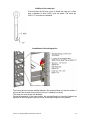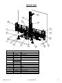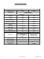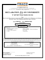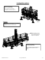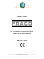
1
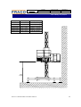
User Guide
All you need to know about FRACO
mast-climbing work platforms
FRSM-1500
User Guide FRSM-1500, rev. 01 - 10/2004
All rights reserved. Any reproduction in whole or in part is prohibited without the written consent of FRACO Products Ltd
Model
All
Information
Date of issue
2006-12-06
Bulletin n°
U-T-0003-A
Mast climbing work platform
High priority warning: Height of the first and second wall tie
Amendment to all the FRACO platforms User’s Guide
Please read carefully the present letter and insert it in all your Fraco User’s Guide:
Fraco is changing the anchoring procedure for all types of platforms when using ground base. The most
recent versions of our user’s guide are available on our Web site (www.fraco.com). Please refer to them
for installation procedures with regards to changes below.
The two first ties must be at 10 and 20 feet ( 3m and 6 m) or at the two first accessible structural levels on
the building (max 20’) ( max 6 m ).
This new procedure is to upgrade the safety of our platform during the operation of installation and
dismantling.
The platform must be secured by lifting equipment while installing or dismantling the two first ties. Once
the second tie is in place, the installation continues by the usual procedure; reduce load platform (1/2 load)
except the ACT-4 and the anchoring sequence typical for the type of platform in use as shown below:
FRSM-1500, FRSM-3000, FRSM-8000 :
20 feet ( 6 m )
ACT-8 et FRSM-20 K :
30 feet ( 9 m )
ACT-4 :
40 feet ( 12 m )
For more information, contact our Technical Department:
Julie Rainville
Technical Service Director
Fraco Products
T: 800-267-0094 / 450-658-0094
F: 450-658-8905
2001© Les Produits FRACO Products ltée/Ltd.
1
Technical
Model
All
Date of issue
2007-01-16
Bulletin n°
B-T-0004-A
Mast climbing work platform
New specifications for use of free-standing bases for 20k, FRSM-8000,
FRSM-3000, FRSM-1500, ACT-4 and ACT-8
Amendment to FRACO platforms User’s Guides for models indicated above
Please read the following carefully and insert it in your Fraco User’s Guides:
Here are the new specifications for use of free-standing bases for 20K, ACT-4 and
ACT-8, FRSM-3000, FRSH-1500.
-
The outriggers of the deck must not be extended longer than the outriggers
of the base (maximum 3 planks, +/- 30’’[76 cm]). See attached drawing.
Do not extend the top deck outriggers if the bottom ones are already
extended.
The maximum wind speed for use and installation is 22 mph (35 km/h).
Use of portable crane, monorail, hard roof or weather enclosure is forbidden
without adding ties.
The outriggers of the base (back) must be fully open.
Here are the new specifications for usage of free-standing bases for FRSM-8000.
-
The outriggers of the deck must not be extended longer than the outriggers
of the base (maximum 5 planks, +/- 60’’[152 cm]). See attached drawing.
Do not extend the top deck outriggers if the bottom ones are already
extended.
The maximum wind speed for use and installation is 22 mph (35 km/h)
Use of portable crane, monorail, hard roof or weather enclosure is forbidden
without adding ties.
The outriggers of the base (back) must be fully open.
For further information or any question please contact:
Jean-François Laurin T.P. or Jean-Sébastien Lasnier T.P.
Telephone : 450-658-0094
Toll Free : 800-267-0094
Fax : 450-658-8905
2001© Les Produits FRACO Products ltée/Ltd.
1/2
Model
All
Technical
Date of issue
2007-01-16
Bulletin n°
B-T-0004-A
Mast climbing work platform
Type
ACT-4
ACT-8
20K
FRSM-8000
FRSM-3000
FRSM-1500
Max. height
60’0” (18.3m)
45’0” (13.7m)
45’0” (13.7m)
42’0” (12.8m)
35’0” (10.7m)
35’0” (10.7m)
Capacity
4 000 lbs (1 815 kg)
8 000 lbs (3 630 kg)
10 000 lbs (4 535 kg)
8 000 lbs (3 630 kg)
3 000 lbs (1 360 kg)
1 500 lbs (680 kg)
FRACO
FRACO
FRACO
FRACO
Max.
height
2001© Les Produits FRACO Products ltée/Ltd.
2/2
Technical
Model
FRSM-1500
Date
2015-07-21
Bulletin n°
1-T-0003-A
FRACO
Locking device for FRSM-1500 mast bolts
Situation :
Mast bolts that are incorrectly tightened can loosen further and disengage.
Affected parts :
All FRSM-1500 mast sections
Corrective measures :
Addition of a mast bolt locking device for all three mast section bolts. Changed the nut to serrated
flange nut. Addition (if it is not already present) of a cotter pin.
Required parts:
1 x 28027155 (Left)
1 x 28027166 (Right)
1 x 28027177 (Centre)
Note :
It is strongly recommended to follow the instruction contained in this technical bulletin to remove all
risk of accident and ensure the safety of the users.
Important:
You can contact Fraco at the following email address or phone number to receive the locking
devices (28027155, 28017166 and 18027177) and serrated flange nuts (ECZ-5065) free of charge,
for all FRSM-1500 mast sections in your possession.
Email address: [email protected]
Phone number: 800-267-0094
For further information or any questions please contact :
Michel Chamberland or Yannick St-Pierre
Telephone : 450-658-0094
Toll free : 800-267-0094
Fax : 450-658-8905
2001© Les Produits FRACO Products ltée/Ltd.
1/2
Addition of the cotter pin
FRACO
If the rod ends do not have a hole to install the cotter pin, a hole
with a diameter of 4mm (5/32") must be drilled. The cotter pin
GOU-1117 must then be installed.
Installation of the locking device
The locking device must be installed between the serrated flange nut and the washer. It
will prevent the rod ends from pivoting if the nut is installed incorrectly.
The cotter pin must secure the assembly.
During the assembly of the mast section, the serrated flange nut must be tightened as
specified in the user guide to prevent it from loosening during use of the platform.
2001© Les Produits FRACO Products ltée/Ltd.
2/2
Congratulations!
You are about to use the excellent
FRACO hydraulic mast-climbing work platform system!
FRACO provides you with the ultimate in
SAFETY, STABILITY, and FLEXIBILITY
while reducing your labor costs by up to 36%.
Due to the advanced technology of FRACO Products,
You can be assured of the OPTIMUM QUALITY in all our products
TOTAL QUALITY
FRACO is an ISO 9001 registered company
The instruction manual and safety rules presented on the following pages will safely
guide you through all the possibilities of this system. The platform cannot be sold or rented
without this user’s guide.
FRACO Products Ltd., reserves the right to modify the platform or its manual without notice, and will
not assume any responsibility for any prejudices that may occur.
The FRACO FRSM-1500 system meets the ANSI, OSHA, CE EN 1495:1997F requirements, except for
the following points: rack and pinion.
Manufacturer
Les Produits FRACO Ltée
Distributor
APPAVE Certified
91 Chemin des Patriotes
St-Mathias-sur-Richelieu
Québec, Canada, J3L 6A1
www.fraco.com
[email protected]
If you have any questions, do not hesitate to call us at:
(450) 658-0094
Canada: 1-800-267-0094
Europe: + 33 (0) 3 44.91.03.53
U.S.A.: 1-888-372 2648
Or fax us at: (450) 658-8905
Table of Contents
Part I:
What You Need To You – General Information
Part II:
Assembly and Installation of the FRACO System
Part III:
Options / Miscellaneous
Part IV:
Operating of the FRACO System
Part I
What You Need to Know – General Information
In This Section:
•
•
•
•
•
Warnings
Identification plate
General View
Technical Information
Conformity Declaration
I-1
I-2
I-3
I-4
I-5
WARNING!
SAFETY IS OUR PRIMARY CONCERN.
For this reason, never remove or alter any part in order to adapt the platform to fit a
specific area of the building.
USE ONLY GENUINE FRACO PARTS
PLEASE READ THE FOLLOWING INSTRUCTIONS CAREFULLY BEFORE
INSTALLATION
FRACO (and/or its importer/representative) cannot be responsible for any property damage,
severe injury or death that may result from failure to comply with the following safety
recommendations and local rules and regulations.
Before operating this FRACO System, the following safety rules must be read and completely
understood.
Mark out, with beacons or barricade tape and forbid the access around the base and the platform. This
should be done according to the local rules.
2- If you use a gasoline engine, do not work in an explosive surrounding. (refineries, etc)
3- The operator should be familiar with the user's guide and understand all the functions of the platform
before operating the platform.
4- Never assume anything. If you have any questions concerning the operation of the FRACO, STOP! Refer
to the user's guide. If you are still unsure, do not continue and call FRACO immediately.
5- In order to use, install or dismantle, a minimum of 2 persons should be on the platform at all times, in case
of a breakdown or rescue.
6- The maximum freestanding height is 11m (35ft) when in use and 3m (10ft) when not in use.
7- This platform must be maintained periodically as well as inspected where required by local laws and
regulations. Refer to the user's guide.
8- In case of an electric storm, DO NOT USE the platform and GET OFF it.
9- For personal safety, when wind exceeds 12,5m/s (28 mp/h) do not use, install or dismantle the platform.
Make sure that the platform is lowered to the minimum height when not in use.
10- It is the responsibility of the operator to ensure that the maximum load and the number of people allowed
on the platform are respected (Refer to the standard load distribution chart).
11- This platform should never be used specifically as an elevator.
1-
Always wear your safety harness when installing and dismantling the mast sections and when
manipulating the planks when passing the wall ties
Before raising or lowering the platform, make sure:
123-
45-
© FRACO Products Ltd.
That the base is properly fixed in position and leveled (see the allowable tolerance in the user's guide).
That all guardrails are in place.
That a visual inspection above and below the platform is done, before each vertical move, to ensure no
protrusions will impede or inhibit the proper movement of the FRACO. Special attention is needed to verify
proper clearance for the walk boards (planks).
Not to exceed the freestanding height 11m (35pi) from the ground and that the platform never exceeds the
last anchor.
That all persons have been alerted.
user’s guide FRSM-1500
I-1
Identification Plate
This plate must be visible at all times.
SERIAL NO.
NO. SÉRIE
NO. SERIE
SERIE NR
Patent pending no : PTC-CA01-01125
MODEL
MODÈLE
MODELO
MODEL
FRSM - 1500
YEAR
ANNÉE
ANO
BOUWJAAR
Vertical travel speed
Vitesse de déplacement vertical
Velocidad de elevación
Verticale verplaatsingsnel heid
}
0 - 13,8 pi/min
0 - 4,2 m/min
Sérial number:
XX XX XXXX
Model number
Platform number
Year of manufacturing
I-2
user’s guide FRSM-1500
© FRACO Products Ltd.
General View
16
2
11
10
3
5
13
7
4
12
Fig.2
8
17
1
Item #
Part #
1
2
3
4
5
6
10050028
13060011
20490634
17490045
15050012
14040021
28493163
28493174
19010067
17490247
17490292
28493196
20490713
20490083-
7
8
9
10
11
12
13
14
15
16
17
© FRACO Products Ltd.
6
14
9
15
Part List
Description
Elevating Unit
Mast section
Protection mesh
Palnk end guardrail
Platform section
Trailer
Stabilizers
Jack
Outrigger
Guardrail
Elevating unit guardrail
Planks
Sliding uardrail
Metal pads
Access staircase
Anchor system
Removable jack pads
user’s guide FRSM-1500
I-3
Technical Information
Trailer
Weight of the trailer
1594 lbs
724.5 kg
Europe : 205 R 14 C
North America : 205-75 R14
Tire dimensions
FRSM-1500
Total length
178 in
4.5 m
Total width
82 5/8 in*
212 cm
Maximum platform length
334 in
8.5 m
Width of the lower work zone
0 in to 27 in
0 m to 0.8 m
Width of the upper circulation and
loading zone
31 in
0.8 m
Lifting speed
13.7 ft / minute
4.2 m / minute
35 ft
11 m
150 ft
45.7 m
29 in
75 cm
Maximum mast height
(without anchors)
Maximum mast height
(with anchors)
Minimum height from the ground
Electric motor
Mast section
(Dimensions / Weight)
Elevating unit
(Dimensions / Weight)
Platform sections
(Dimensions / Weight)
Motor specifications
Required power
Type : FA77BDT90L4BMG2HR,
power 2 CV,
Amp. 3.1, Volt. 230/460V, 3 phase
50 HZ
220V AC, 20A 1phase
Europe : 50 cycles
North America : 60 cycles
5 ft x 21 in x 20 in / 92 lbs
1.54 m x 0.55 m x 0.51 m / 42 kg
51 in x 33 in x 26 in / 1064 lbs
1.3 m x 0.86 m x 0.66 m / 484kg
75 in x 33 in x 26 in / 250 lbs
1.91 m x 0.86 m x 0.66 m / 113 kg
Generator
HX-3000 (Option)
I-4
3 000 Watt
user’s guide FRSM-1500
© FRACO Products Ltd.
Les Produits Fraco Ltée
91, Chemin des Patriotes, St-Mathias-Sur-Richelieu, Quebec, Canada J3L 6B6
Tel: (450) 658-0094 Fax: (450) 658-8905 CDA: 1-800-267-0094 USA: 1-888-372-2648
www.fraco.com email: [email protected]
DECLARATION
OF CONFORMITY
N° 00770077/5162/760/01/10/1304
Type:
Device for the lifting of persons or persons and objects, involving a risk of falling from vertical height of
more than 3 meters. Mast climbing work platform, single or twin mast.
Brand: FRACO Model: FRSM-1500
Serial Number:
Technical details:
In single mast:
¾ Rated load / Number of persons:
¾ Working height:
¾ Length / Width of platform:
¾ Trailer:
680 kg / 2 persons
11m (Freestanding) – 100m (with anchorages)
8,5m / 1,65m
Towable trailer
This model complies with all relevant provisions of the machinery directive 2006/42/CE (95/16/CE modified) on the approximation
of the laws of the Member States. This model complies with the essential safety and health requirements applicable to it. This
declaration concern exclusively the machines in the condition in which they entered the market, and exclude the components that
have been added and/or the operations carried out afterward by the final user.
Notified Organism
APAVE Parisienne
No d’identification : 0077
13 à 17, rue Salneuve – 75854 PARIS CEDEX 17
Technical file
SARL Fraco
420 rue des Érables – F-60710 CHEVRIÈRES
FRANCE
______________________________
La Vice-présidente
Les Produits FRACO Ltée
St-Mathias-Sur-Richelieu
29 décembre 2009
Claudette L'Heureux
TRANSLATED FROM ORIGINAL NOTICE
Part II
Installation of the platform
In This Section:
•
•
•
Assembly of the FRACO platform
o Installation of the platform
o Positioning the elevating unit
o Platform sections
o Guardrails
o Outriggers
o Planks
o Plank-end guardrails
o Protection mesh
o Access staircase
o Single mast blocking system
Mast sections
o Assembly of the mast sections
o Installation of the mast sections
o Installation of the mast end section
Anchors
o Anchor position
o Anchoring system
o Minimal opening of the turnbuckles
o How to level the mast with the anchoring system
o Installation of the anchors
o Anchor bolted to a brick shelf
o Anchor bolted to a structural beam
o Anchor for structure of concrete beam
o Horizontal concrete anchor
o Anchor welded to a brick shelf
o Anchor welded to a structural “H” beam
o Angle wall tie
o Epoxy anchor
II-1
II-2
II-3
II-5,15
II-7
II-8
II-9
II-10
II-11
II-17
II-12
II-13
II-14
II-18
II-19
II-20
II-21
II-22
II-25
II-26
II-27
II-28
II-29
II-30
II-31
II-32
Installation of the FRACO platform
Verify the ground bearing capacity and ensure that it is sufficient to adequately support the
trailer jack pads.
Ground bearing capacity:
Mast height
Capacity
2
0 m (0’) to 30.5 m (100’)
30.5 m to 45.7 m (100’ to 150’)
34 kN/m (700 lb/sq.ft.)
2
44 kN/m (900 lb/sq.ft.)
Installation Type
Distance "L"
Distance "D"
Standard
0.85 m (37 in)
0.75 m (29 ½ in)
1-
Measure precisely the “L” distance between the base and the wall, taking into consideration all the obstacles
that the platform must go around. (Fig. 3, page II-2)
2-
Install the FRACO system (elevating unit and trailer) perfectly perpendicular to the wall at the appropriate “L”
distance.
3-
Pull the hand break to keep the trailer from moving.
***Always install the wooden jack pads under the outrigger jacks ***
4-
Open the front outriggers and deploy them 25 cm.
5-
Ensure that the outriggers are perfectly secured before continuing with the installation. (fig.6 + dét.1)
6-
Extend the outriggers to a maximum (rear : at least 1.15 m (59)). Lower the jacks onto the wooden jack pads
(see instructions on the outriggers)
7-
Level the trailer using a bubble level. After leveling, the wheel on the trailer should turn freely, no load must
rest on the trailer tires.
8-
Ensure that the mast is perfectly vertical and that the trailer is level and stable.
9-
Electric power required: 220V AC, 20A 1 phase, 50 cycles (Europe) or 60 cycles (North America)
10- Use a power cable of sufficient length of type H07RNF or equivalently protected against the weather or
mechanical deterioration.
11- The platform may be used in an interior or exterior environment where the temperature is between -20 and +40
degrees Celsius.
© FRACO Products Ltd.
User’s guide FRSM-1500
II-1
Positioning the elevating unit
5,7m
(18'-9")
"L"
3,7m
(12'-2")
"D"
Lock pin
25490281
Det.1
Jack handle
28491161
Fig.3
Important
If the platform is not in fornt of a structure, extend the
front outriggers to their maximum.
Important
Det. 2
Maximum freestanding height: 11m (35’)
Maximum heighton trailer: 30m (100’)
Elevating unit
10050028
Installation:
1-Extend the rear outriggers to 1.15 m (3’-3’’)
.
2-Extend the front outriggers to 25cm (10”) and adjust the
angle of the opening using the pin (Dét. 1)
3-Install the elevating unit on the trailer perfectly
perpendicular to the wall using appropriate “L” distances.
(see page II-1)
Trailer
14040021
"L"
4-Postion the pads under the jacks. Use the pin to secure
them in place. (fig.6)
5-Level the base using the crank and the outriggers. (Det. 2)
Fig.4
Stabilizer
28493163
28493174
Lock pin
GOU-5010
Lock pin
25490281
Fig.6
Slipper
28493196
II-2
Fig.5
User’s guide FRSM-1500
© FRACO Products Ltd.
Opening up the platform sections
Step 1
Installation:
1-Remove the guardrails and then the pin that holds the platform section to the elevating unit (see Fig.8 and Det.3)
2-Pivot the platform sections towards the outside. (Fig. 7)
Guardrail to
be removed
17490247
Lock
25490022
Det. 3
See detail 3
Fig.8
Platform section
15050012
Fig.7
© FRACO Products Ltd.
User’s guide FRSM-1500
II-3
Opening up the platform sections
Step 2.
Installation:
1-After removing the locks and pins, extend the platform sections to their
position; replace the locks and pins to secure the sections. (Det.4)
Caution: Never pivot the exterior platform sections towards the front.
See detail 4
Fig.9
Platform after openning
Lock pin
28493691
Det. 4
II-4
Lock
GOU-5030
User’s guide FRSM-1500
© FRACO Products Ltd.
Guardrails
Step 1
Installation
1-Remove the safety pins. (Det.5)
2-Remove the guardrails that must be relocated. (Det.6)
3-Lock the guardrails. (Det.5)
Safety pin
GOU-5020
Det.5
Det.6
See detail 5
Fig.10
© FRACO Products Ltd.
User’s guide FRSM-1500
II-5
Guardrails
Step 2
Installation
1-Place the guardrails in such a way to cover all openings to prevnt risk of falling. (Det.8)
2-Secure them using a safety pin. (Det.7)
Épingle de
sûreté
GOU-5020
Access door
17490292
Det.7
Guardrail to
their final place
Det.8
Fig.11
II-6
User’s guide FRSM-1500
© FRACO Products Ltd.
Outriggers
Installation:
1- Insert the outriggers in the adaptors found in the platform section. (Det. 10).
2- Insert the pin and secure it in place with the the cotter pin (Det.11)
IMPORTANT
The outriggers cannot be extended more that 0.8 m (30 in)
Never place any load on the planks at any time.
Lock with washer
25490088
Outrigger adaptor
Det.11
Cotter pin
GOU-1120
Det.10
Outrigger adaptor
See detail 10
See detai l11
Fig.12
© FRACO Products Ltd.
User’s guide FRSM-1500
II-7
Plank ties
Installation:
1-Install the ties in such a way as to hold the outriggers and the planks together.
2-Nail or screw the ties to the planks in order to prevent them from moving.
#1 category spruce or equivalent. Nominal dimensions 50 mm x 254 mm (2’’
x 10’’) for a span of less than 1.50 m (5’)
Planks must be 15 cm (6’’) from the wall
Only use planks that are approved by the local authorities.
IMPORTANT
Never place any load on the planks at any time.
Nails / screws
Det.12
Plank tie
20490050
Det.13
See detail 12
Fig.13
II-8
User’s guide FRSM-1500
© FRACO Products Ltd.
Plank-end guardrail
Installation:
1-Install the plank-end guardrails at the end of the planks in the work zone.
2-Secure them in place using nails or screws.
3-Place guardrails at any place required to prevent the risk of falling.
4-Once all the anchors are in place and secured, install the plank-end guardrails in
such a way as to ensure that they do not interfere with the anchors when moving up or
down.
Plank-end
Guardrail
1790045
Det.14A
Nails / screws
Guradrail - anchoring area
Fig.14C
Det.14B
See detail 14C
Fig.14A
See detail 14A & 14B
© FRACO Products Ltd.
User’s guide FRSM-1500
II-9
Protection mesh
Installation
1-After installing the masts, insert the protection mesh in the anchor points of the elevating unit hooks (Det. 15) to protect the
personnel from risk of injury. Secure the mesh in place using a locking pin. (Det. 16)
Protection mesh
20490634
Anchoring point
for the protection mesh
Locking pin
GOU-5040
Det.15
Det.16
See detail
15-16
Fig.15
II-10
User’s guide FRSM-1500
© FRACO Products Ltd.
Access staircase
Installation
1-Remove the access guardrail and place the staircase on the platform. Replace the guardrail by aligning the hole of the platform
with the holes of the staircase. (Det.18)
2-Secure the guardrail using the safety pin. (Det.19)
Safety pin
GOU-5020
Access guardrail
17490292
See detail 18
Det.18
Stairs
20490713
A
Det.17
See detail
17-18
Fig.16
© FRACO Products Ltd.
User’s guide FRSM-1500
II-11
Assembly of the mast sections
Installation
1-Join the male and female sections.
2-Loosen the mast section bolts (Det.21 page II-13) and pivot them to join
the mast sections together and tighten the bolts.
IMPORTANT
Mast section
13060033
1-Do not add more than 6 mast sections (7 scetions total) to the
Fraco system. The maximum freestanding height that the
platform can reach is 11m (35’).
2-Be aware of the direction ofthe mast sections.
3-Always uniformly distribute the mast sections on the platform
during installation.
See detail 21
Det. 21
Fig.23
Torque– 206 Newton *-meter
(152 Foot * pound)
Do not exceed the following vertical tolerances
- 1.25 cm (1/2") for a 3 m (10') mast
- 2 cm (3/4") for a 6 m (20') mast
- 2.5 cm (1") for the total mast height
II-12
User’s guide FRSM-1500
© FRACO Products Ltd.
Installation of the mast sections
Installation
1-Place the mast sections on the platform, uniformly distributed on each side of the elevating unit.
2-Lift the platform to the height of the last mast section and slide the next section on the other.
3-Follow the assembly instructions on page II-12.
Mast section
13060033
Fig.22
Torque– 206 Newton *-meter
(152 Foot * pound)
© FRACO Products Ltd.
User’s guide FRSM-1500
II-13
Installation of the mast end section
Installation
1-Once all the mast sections are installed, place the mast end section last.
2-Elevate the platform to the height of the last mast section, and slide the mas tend section on the other mast section.
3-Follow the installation instructions on page II-12.
End mast section
13060022
See detail 22
Fig.24
Torque– 206 Newton *-meter
(152 Foot * pound)
Det.22
II-14
User’s guide FRSM-1500
© FRACO Products Ltd.
Outrigger guardrails
Installation at more than 40cm (16’’) of the work surface
Installation
1- Install all the guardrails in required places in order to prevent the risk of falling.
2- Secure all the gusrdrails using a pin with washer and a cotter pin.
3- Insert planks 50mm X 100mm (2" X 4") in the guardrail and hold them in place
using nails or screws.
4- A board of 15cm (6’’) must be installed at the bottom of the guardrail to prevent
debris from falling.
Caution !
Never place any load on the
planks at any time.
Plank
Locking pin with washer
25490088
Det.23
Outrigger guardrail
17490067
Det.24
Cotter pin
GOU-1120
Plinthe 15 cm (6")
See detail 24
See detail 23
Fig.25
© FRACO Products Ltd.
User’s guide FRSM-1500
II-15
Work zone outrigger guardrails
Installation at less than 40cm (16’’) from the work surface
Installation
1-Insert the front handrail supports in all the work zone outriggers. (Det. 26)
2-Secure the front handrail supports using a pin with washer 11mm and a cotter pin. (Det. 26)
3-Install the front handrails on the supports and secure thatm inplace with a locking pin. (Det. 25)
4-To join two handrails, insert the handrail junction tube on two handrail extremities and secure them with a locking pin. (Det. 27)
5-A board of 15cm (6’’) must be installed at the bottom of the outrigger guardrail to prevent debris from falling.
It is important to install guardrails at any place required to prevent the risk of falling.
IMPORTANT
Never place any load on
the planks at any time
Locking pin
25490011
Cotter pin
GOU-1120
Junction tube
20490353
Safety pin
GOU-5040
Det 27
Det.25
Locking pin
With washer
25090088
Det.26
Cotter pin
GOU-1120
Fig.26
See detail
25-26-27
Outrigger guardrail
17490056
II-16
User’s guide FRSM-1500
© FRACO Products Ltd.
Single mast locking system
Installation
1-Insert the outrigger lock in the outriggers located at each extremity of the platform. (Det 28)
2-Insert the locking wheel at the end of the outrigger. (Det 29)
3-Secure the wheel to the outrigger using a pin with washer and a cotter pin. (Det. 29)
4-Adjust the length of the outriggers so that the distance with the wall is at least 3 cm (1 ½’’)
5-Tighten the bolts on the outrigger lock at the base of the platform section. (Det 28)
IMPORTANT
Never place a load on the
outriggers at any time
Locking pin with wahser
25490088
Cotter pin
GOU-1120
Outrigger lock
20490072
Wheel
20490263
Det.28
Fig.27
See detail 28
© FRACO Products Ltd.
User’s guide FRSM-1500
II-17
Anchor position
The anchors are required when working at a height exceeding 11m (35’)
Maximum height allowed on trailer: 30m (100’)
Fig.28
IMPORTANT
1-The first anchor must be installed before placing a load on the platform.
2-Load the platform only with mast sections required to reach the next anchor level.
3-In work situation, the platform may exceed the last anchor by 1.5m (5’)
First anchor:
Maximum of 9.1 m (30') above ground level.
Subsequent anchors:
Maximum of 6.1 m (20') between each anchor.
*-For the installation of the anchors only,
Il is permitted to exceed the last anchor by 6.1 m (20’) with a maximum load of 454 kg (1,000
lbs), including 2 men with tools, during anchor installation.
II-18
User’s guide FRSM-1500
© FRACO Products Ltd.
Anchoring system
Fig.30
Anchporing system well assembly
Mast section
13060022
Bolt & nut
Anchor adaptor
Reinforced tube
Anchor tube
Swivel collar
Fig.29
© FRACO Products Ltd.
Locking pin with lock
Exploded anchoring system
User’s guide FRSM-1500
II-19
Minimal opening of the turnbuckles
Length of the
anchoring tubes
H
A : 0.71m
B: 0.86 m
0.70 m
A: 1.0m
B: 1.17 m
0.97 m
W
0.56 m
0.78 m
0.71 m
1.05 m
Wall
"W"
"H"
Fig.31
II-20
User’s guide FRSM-1500
© FRACO Products Ltd.
How to level the mast using the anchoring system
IMPORTANT
Do not exceed the following vertical tolerances:
-1.25 cm (1/2") for a mast of 3 m (10').
-2.0 cm (3/4") for a mast of 6 m (20').
-2.5cm (1") for the total height of the mast
- Ensure that the platform and the trailer are perfectly parallel to the wall.
- Ensure that the platform is perfectly vertical using a bubble level of 1.2 m (4’) length.
- If the platform leans towards the building, lift the front jacks and tighten in place.
- If the platform leans away from the building, lift the rear jacks and tighten in place.
- Load the platform uniformly to prevent it from being unbalanced.
- In case of difficulties in leveling the platform, use a strap and ratchet to level.
Fig.32
© FRACO Products Ltd.
User’s guide FRSM-1500
II-21
Installation of the first anchor
When the assembly of the platform at ground level is completed, the first anchor must be
installed to be able to raise the platform.
The disrespect of these installation procedures can cause serious bodily and material damages, including death. If a
situation other than one described here arises, contact your Fraco representative. Fraco Products Ltd and/or its
importer/representative cannot be held responsile in any case.
First anchor
After assembling the platform at ground level, three techniques are available to install the first anchor. At all times, the
platform cannot have more than 2 men and their tools on it.
1-1st Anchor;
3,1m
(10') max.
9,1 m
(30'-0") max.
After installing the platform according to this guide, lift
the platform to a maximum of 9.1 m (30’) above ground
and proceed to the installation of the first anchor.
II-22
User’s guide FRSM-1500
© FRACO Products Ltd.
Installation the anchpors (cont’d)
2-Work from inside the building and positionning in the mast:
At the level of the first anchor, position a man in the
mast and one inside the building with all the required
equipment for one anchor. The man inside must
supply the man outside with the equipment to proceed
to the installation of the forst anchor.
ALWAYS wear a safety harness, securely fastened
to the structure when executing this procedure.
© FRACO Products Ltd.
User’s guide FRSM-1500
II-23
Installation of the anchors (cont’d)
3-Held with a crane, boom truck or forklift:
Applicable only for single unit on ground base.
Strap the extremity of the mast to the crane, boom truck or
forklift and apply a light pressure to the strap. Raise the
platform to the level of the first anchor and install it from the
platform.
With trailer
Raise the platform to the level of the first anchor and install by working from the platform.
Subsequent anchors
Raise the platform to the level of the next anchor and install it by working from the platform. The maximum load allowed is
454 kg (1 000 lbs) uniformly spread out, and including the workers and their tools.
II-24
User’s guide FRSM-1500
© FRACO Products Ltd.
Anchor bolted to a brick shelf
Caution: Before proceeding to the installation, be sure to have all the
required authorizations.
Installation
1- Install the wall tie and the anchor tube.
2- Determine the place to drill the holes for the turnbuckles using page II-12.
3- Adjust the verticality of the tower with the turnbuckles.
4- Drill the hole in the brick shelf for the anchor tube pin.
5- Ensure that all the pins are in place and that they are secured with cotter pins.
6- Secure the anchor by installing the transversal tube.
Fig.36
Structural iron angle
© FRACO Products Ltd.
User’s guide FRSM-1500
II-25
Anchor bolted to a structural beam
Caution: Before proceeding to the installation, be sure to have all the
required authorizations.
Installation
1- Install the wall tie and the anchor tube.
2- Determine the place to drill the holes for the turnbuckles using page II-12.
3- Adjust the verticality of the tower with the turnbuckles.
4- Drill the hole in the brick shelf for the anchor tube pin.
5- Ensure that all the pins are in place and that they are secured with cotter pins.
6- Secure the anchor by installing the transversal tube.
Fig.37
Structural "H" beam
Anchor for structural "H" beam
Fig.38
Structural "C" channel
Anchor for structural "C" channel
II-26
User’s guide FRSM-1500
© FRACO Products Ltd.
Anchor for structure or concrete beam
Caution: Before proceeding to the installation, be sure to have all the
required authorizations.
Installation
1- Install the wall tie and the anchor tube.
2- Determine the place to drill the holes for the turnbuckles using page II-12.
3- Adjust the verticality of the tower with the turnbuckles.
4- Drill the hole in the brick shelf for the anchor tube pin.
5- Ensure that all the pins are in place and that they are secured with cotter pins.
6- Secure the anchor by installing the transversal tube.
The concrete must have a minimum capacity of 35 Mpa.
Concrete anchor
Fig.39
See detail 30
HILTI, HSLG-RM 12/10
or equal approved
Anchor tube
© FRACO Products Ltd.
Det. 30
User’s guide FRSM-1500
II-27
Horizontal concrete anchor
Caution: Before proceeding to the installation, be sure to have all the
required authorizations.
Installation
1- Install the wall tie and the anchor tube.
2- Determine the place to drill the holes for the turnbuckles using page II-12.
3- Adjust the verticality of the tower with the turnbuckles.
4- Drill the hole in the brick shelf for the anchor tube pin.
5- Ensure that all the pins are in place and that they are secured with cotter pins.
6- Secure the anchor by installing the transversal tube.
The concrete must have a minimum capacity of 35 Mpa.
See detail 31
HILTI, HSLG-RM 12/10
or equal approved
Fig.40
Det.31
Anchor tube
II-28
User’s guide FRSM-1500
© FRACO Products Ltd.
Anchor welded to a brick shelf
Caution: Before proceeding to the installation, be sure to have all the
required authorizations.
Installation
1- Install the wall tie and the anchor tube.
2- Determine the place to drill the holes for the turnbuckles using page II-12.
3- Adjust the verticality of the tower with the turnbuckles.
4- Drill the hole in the brick shelf for the anchor tube pin.
5- Ensure that all the pins are in place and that they are secured with cotter pins.
6- Secure the anchor by installing the transversal tube.
Fig.41
See detail 32
127mm
(5") min.
Det.32
Weld
Minimum welding length
© FRACO Products Ltd.
User’s guide FRSM-1500
II-29
Anchor welded to a structural beam
Caution: Before proceeding to the installation, be sure to have all the
required authorizations.
Installation
1- Install the wall tie and the anchor tube.
2- Determine the place to drill the holes for the turnbuckles using page II-12.
3- Adjust the verticality of the tower with the turnbuckles.
4- Drill the hole in the brick shelf for the anchor tube pin.
5- Ensure that all the pins are in place and that they are secured with cotter pins.
6- Secure the anchor by installing the transversal tube.
127mm
See detail 33
(5") min.
Fig.44
Anchor for structural "H" beam
Weld bed
Det.33
Minimum welding length
Fig.43
Anchor fot Structural "C" channel
II-30
User’s guide FRSM-1500
© FRACO Products Ltd.
Angle wall tie
Caution: Before proceeding to the installation, be sure to have all the
required authorizations.
Installation :
1- Install the wall tie and the anchor tube.
2- Determine the place to drill the holes for the turnbuckles using page II-12.
3- Adjust the verticality of the tower with the turnbuckles.
4- Install the concrete anchor for the anchor tube pin.
5- Ensure that all the pins are in place and that they are secured with cotter pins.
6- Secure the anchor by installing the transversal tube.
The concrete must have a minimum capacity of 35 MPa.
127mm
See detail 33
(5") min.
Fig.44
Anchor for structural "H" beam
Weld bed
Det.33
Minimum welding length
Fig.43
Anchor fot Structural "C" channel
© FRACO Products Ltd.
User’s guide FRSM-1500
II-31
Epoxy anchor
Caution: Before proceeding to the installation, be sure to have all the
required authorizations.
Installation on concrete wall/slab:
12345678910-
Determine the place to drill the holes for the turnbuckles using page II-12.
Drill the holes at the required places and clean out any debris that may still be in the hole.
Inject the epoxy into the hole using an epoxy screen.
Position the treaded rod and bolt the anchor plate temporarily, while the mixture hardens.
Once the epoxy has hardened, tighten the bolts.
Install the wall tie and the central tube.
Adjust the verticality of the tower using the turnbuckles.
Install the concrete anchor for the central tube pin.
Ensure that all the pins are in place and that they are secured with cotter pins.
Secure the anchor by putting tension on the turnbuckles and putting the central tube in
compression.
Installation on a concrete wall/slab with brick:
123456789101112-
Determine the place to drill the holes for the turnbuckles using page II-12.
Drill the holes at the required places and clean out any debris that may still be in the hole.
Inject the epoxy into the hole using an epoxy screen.
Ensure that the mixture has hardened in the concrete and not in the brick wall.
Position the treaded rod and bolt the anchor plate temporarily, while the mixture hardens
Once the epoxy has hardened, tighten the bolts.
Install the wall tie and the central
Determine the place to install the anchors for the turnbuckles using page II-12
Adjust the verticality of the tower using the turnbuckles.
Install the concrete anchor for the central tube pin.
Ensure that all the pins are in place and that they are secured with cotter pins.
Secure the anchor by putting tension on the turnbuckles and putting the central tube in
compression.
.
The concrete must have a minimum capacity of 35 MPa
See detail 35
HILTI, HSLG-RM 12/10
or equal approved
Fig.45
Anchor tube
II-32
User’s guide FRSM-1500
Det.35
© FRACO Products Ltd.
Part III
Options / Miscellaneous
In This Section:
•
Configuration options
III-1
Configuration options
Dimensions of the platform:
4.5m x 1.7m(176po x 68po)
Use the platform in transportation
“configuration”. (See Fig.5 page II-3)
Fig.47
IMPORTANT:
Always balance out the platform. Do not extend
the platform sections on one side only.
When installing in front
wall covering the whole
length of the platform
Fig.48
Dimensions of the platform:
8.2m x 0.9m (324po x 34po)
Extend the platform sections as illustrated on
pages 3-4-5-6 for complete use of the
platform.
© FRACO Products Ltd.
User’s guide FRSM-1500
III-1
Part IV
Operating the platform
In This Section:
•
•
•
•
•
•
•
•
•
Load distribution 8.3 m (27’-2’’)
Load distribution, closed platform
How to raise/lower the platform
Emergency procedure
Procedure for mast, platform and anchor dismantling
Maintenance
Drop test
How to load the platform
Moving on site / platform transportation
IV-1
IV-2
IV-3
IV-4
IV-5
IV-8
IV-9
IV-10
IV-11
Load Distribution
8.3m (27’-2’’) Configuration
340 Kg
(750 lbs)
340 Kg
(750 lbs)
Fig.49
Concrete block is to only show
how to sread the load on the platform
according to the platform capacity
Working area
2 workers
Fig.50
28,3m (27'-0 5/8")
Nominal load: 680 kg (1,500 lbs) including 2 workers.
-
Keep the loads as close as possible to the elevating units.
IMPORTANT
Never place any loads in the working or circulation zones.
© FRACO Products Ltd.
User’s guide FRSM-1500
IV-1
Load Distribution
Single Mast Configuration, closed platform
250 Kg
(550 lbs)
250 Kg
(550 lbs)
Concrete block is to only show
how to sread the load on the platform
according to the platform capacity
Working area
2 workers
Fig.51
Wall
Nominal load: 500 kg (1,100 lbs) including 2 workers.
-
The load must be distributed uniformly on the platform.
Important
1-Fold the platform sections and secure them to the elevating unit.
(Section II, page 3)
2-Close the rear outriggers to liberate the space between the wall and
the platform.
3-Open the front outriggers to their maximum and secure.
(Section II, page 1)
The load must be placed on the platform sections that
do not pivot, and must be distributed along the length
of the platform section.
IV-2
User’s guide FRSM-1500
© FRACO Products Ltd.
How to raise / lower the platform
Precautions to take before using the platform
1-Verify that the platform trajectory is free of any obstacles.
2-Never use the platform when winds exceed 45 km/h (28 mph).
3-Warn personnel when the platform will travel along the mast.
1-After road transportation, activate the bypass system in
the control panel.
2-Raise the platform at least 152mm (6”) to liberate the
limit switch.
3-Desactivate the bypass then turn the circuit key to “ON”.
Then press the appropriate button to raise or lower the
platform as desired.
4-Release the button when the desired height is reached.
Emergency stop
Up button
Down button
Important :
After using the emergency
stop button, you must rearm
the system by using the
contact circuit found in the
control panel.
(Fig.52)
Fig.53
Starting Procedure:
1-Place the selector button to 220V
2-Place the circuit key to “ON”
Groupe électrogène
Generator
220V
On
Réarmement
Start
Défaut / Fault
Arrêt
Off
On
Off
Hors tension
Marche
Circuit
Sélecteur / Selector
Tension 220 V
Dérive / By pass
FRSM-1500
Désactivé
Off
Activé
On
30010161-03
Fig.52
The buttons are of "2 phase" type
A light pressure will use the unit’s “first” speed.
Press completely, and the unit’s « second » speed will engage.
© FRACO Products Ltd.
User’s guide FRSM-1500
IV-3
Emergency Procedures
Generator
WARNING:
In case of involuntary stopping of the platform
1-Turn the selector key tp “generator”
2-Turn the circuit key to on
3-Use the raise or lower button, as desired.
1-Verify if the “Tension 220V” light signal is lit.
If so, go to #2. If not, verify the platform power supply or use the self
descent device in the control panel. Apply gentle pressure to control your
descent to the nearest exit. (For use with the generator, see #5).
Lowering
control arm
See detail 37
2-If the light signal is on, start the system with the circuit key in the
“Start” position.
3-Verify if the “Fault” light signal stays on, lower the platform to the
ground by activating the by pass key.
4-If none of these procedure work, use the manual descent.
5- Contact your FRACO representative for verification of your platform.
Fig.56
Control panel
Manual descent:
1-Place the selector key to the “Off” position.
2-Activate the lever located in the control panel in
intermittent fashion to reach the desired level.
3-The platform must be inspected by a Fraco technician
before it is used again.
Groupe électrogène
Generator
220V
On
Réarmement
Start
Défaut / Fault
Arrêt
Off
On
Off
Hors tension
Marche
Note : For each emergency stop, proceed to starting the
platform as described above in “Involuntary stop” #1.
Circuit
Sélecteur / Selector
Tension 220 V
Be careful not to engage the emergency brake during
your descent. If this occurs, you must contact a Fraco
technician to reset the circuit.
Dérive / By pass
FRSM-1500
Désactivé
Off
Activé
On
30010161-03
Generator access door
Fig.57
Emergency
stop
Up
button
Down
button
Generator
(Optional)
Fig.54
Fig.55
IV-4
User’s guide FRSM-1500
© FRACO Products Ltd.
Procedure for mast, platform and anchor dismantling
Warning:
Do not dismantle the mast in sections of more than 6.1 m (20 ft) when using a forklift, crane or boom truck.
When dismantling manually, do not dismantle in sections of more than 1.5 m (5 ft)
Notes:
Unload the platform of all material that is not required for the dismantling of the mast and anchors.
When dismantling, the maximum load supported by the platform (men, tools and mast sections) must be 454 kg
(1,000 lbs).
Start dismantling the highest anchor, followed by each subsequent anchor as the platform is lowered.
If the mast sections exceed the last anchor, start by removing the mast sections that exceed the last anchor.
Otherwise, start by removing the anchor before dismantling the masts.
Steps to follow when dismantling the anchors:
1)
2)
3)
4)
5)
6)
Remove the transversal tube between the anchor tubes.
Remove the articulated collars of the transversal tube that connect to the anchor tubes.
Continue to release the tension on the anchor tubes until the pins can be easily removed.
Do not hit the cotter pins to remove them.
Remove the anchor tubes.
Remove the wall plates from the lateral arms and repair the wall if necessary.
Trasversal tube
Lock
Anchor tube
Anchor tube
Wall
Fig.58
© FRACO Products Ltd.
User’s guide FRSM-1500
IV-5
Procedure for mast, platform and anchor dismantling
Steps to follow to remove the mast sections:
Manually:
1- Bring the platform just under the joint of the mast section you wish to dismantle.
2- Do not remove more than 1.5 m (5 ft) at a time.
3- Loosen the three (3) tower bolts.
Remove the mast section and place it on the platform. Ensure that the load is evenly distributed on the
platform.
4- Repeat steps 1 to 4 to the following anchor.
With a crane (or forklift or boom truck):
1)
2)
3)
4)
5)
6)
7)
IV-6
Strap the top of the mast to the crane, forklift or boom truck and apply a light tension to the strap.
Remove the required anchor(s) for the length of mast to be removed by starting with the highest anchor.
Bring the platform just under the joint of the mast section you wish to dismantle.
Do not remove more that 6.1 m (20 ft) at a time.
Loosen the three (3) tower bolts.
Remove the mast section using the crane.
Repeat steps 1 to 6 as many times as required.
User’s guide FRSM-1500
© FRACO Products Ltd.
Procedure for mast, platform and anchor dismantling
To remove the anchor closest to the ground, on ground base:
1)
2)
3)
4)
5)
6)
Strap the top of the mast section to a crane, forklift or boom truck and apply a light tension on the strap.
Remove the last anchor.
Lower the platform to the ground.
Remove and replace all the guardrails, fold the platform closed (page II-3) remove the plank ties, the
planks and the outriggers.
Loosen the three (3) tower bolts.
Remove the mast section using the crane (forklift or boom truck).
IMPORTANT:
These instructions are for the dismantling of a regular FRSM-1500 using a crane, forklift or boom truck. If you
have any questions or doubts as to the sequence of steps or in the procedure, contact your FRACO
representative.
Fig.58
Stabilizer
28493163
28493174
Removable jack pads
28493196
Lock
GOU-5010
© FRACO Products Ltd.
User’s guide FRSM-1500
Det.38
IV-7
Maintenance
IMPORTANT NOTE
The frequency and the extent of the inspections and periodic tests depend on national rules and regulations,
constructors specifications the operating conditions and the frequency of use. Normally, it is not necessary to
dismantle parts during routine examinations, unless there is a doubt as to the reliability or the safety. Lifting the
hood, inspection doors and the fact of putting the platform into transportation configuration are not considered as
a dismantling.
Daily
Daily Inspection Sheet
ü
During verifications, stop the unit and remove the key from the “selector” switch.
ü
Lock the the electrical box to limit the access to authorized personnel only;
ü
Verify the verticality of the mast with a 1 m (3 ft) level (in both directions);
ü
Clean any concrete, mortar or other deposits that could impede the proper functionning of the platform.
Weekly
ü
Verify the state of the different bearings.
ü
Verify that there is no distortion of the metal components in parts such as the platform sections, mast sections, the
base, etc. A distortion may occur following improper equipment handling.
Half-Yearly
ü
Verify the proper functionning of the brakes by performing a drop test (see page IV-9)
Monthly / Annually
Preventive Maintenance Sheets
ü
Repaint parts or touch up areas susceptible to rust.
ü
If parts must be replaced, use only genuine Fraco parts.
-In case of doubt or anomalies, contact your FRACO representative.
IV-8
User’s guide FRSM-1500
© FRACO Products Ltd.
Drop Test
Procedures:
1-Place the main switch to the “STOP” position.
2-Open the electric panel and replace the key (Det. A) so that the section with the blue wires is connected.
3-Close the electric panel.
4-Place the main switch to the “ON” position. An alarm will sound indicating that the platform is in “TEST” mode.
5-Load the platform with the required nominal load.
6-Ensure that there is no one on the platform and that there are no obstacles in the platform trajectory.
7-With the lever, raise the platform to a height of about 3 m (10 ft).
8-Press on the descent button. The unit will free fall until the centrifugal brake is activated on its own.
9-If the centrifugal brake does not activate, or if there is an improper functioning, release the descent button
immediately. The platform will stop.
10-If the test is conclusive and the centrifugal brake engaged, turn the key to OPERATION mode
(red and black wire) and restart the platform.
11-However, in case of improper functioning, contact your FRACO representative.
12-The centrifugal brake must engage when the platform has fallen between 1 m and 2.5 m (3’-4” and 8’-2”).
Operating connector
See detail 37
1 fil noir,
1 fil rouge
Fils bleu
Det. 37
Emergency brake
self test connector
Fig.60
Interruptor key
To re-engage the brake
loose the collar and insert
the interruptor key
and tight the collar.
See detail 38
Key
Collar
Fig. 59
Det. 38
© FRACO Products Ltd.
User’s guide FRSM-1500
IV-9
How to load the platform
For road transportation
1-Position all the guardrails as illustrated on pages II-5 & II-6.
2-Lift the jacks and close the trailer outriggers and lock them in place.
3-Remove the planks, outriggers and place them on the platform sections along with the mast
sections. Fold the platform sections and secure in place as illustrated on page II-3.
4-Remove the wooden jack pads. (fig.38)
Mast section
Acces stair
Fig.61
Stabilizer
28493163
28493174
Removable jack pads
28493196
IV-10
User’s guide FRSM-1500
Lock
GOU-5010
Det.39
© FRACO Products Ltd.
Moving on site / platform transportation
When moving the unit on trailer on site, apply the following rules:
12345-
Ensure that the ground is level and that it can support the weight of the platform in the direction it will be
moved.
Ensure that nothing will impede the moving of the platform (electric wires, balconies,…)
Lift and close the trailer jacks. (Det.40 & 43)
Slowly move the whole platform to the desired location.
Position the trailer and level the platform. (page II-2)
Transportation:
1-Repeat steps 1 to 3 from the moving section above.
2-Fold in the platform sections.
3-Lower the platform using the manual arm located in the control panel, until it rest on the rubber bumpers.
4-Tie all the movable parts to prevent movement or loss during transportation.
Jack handle
28491161
Safety pin
25490281
Det. 40
Det.41
Lock
GOU-5040
Det 43
Lock
GOU-5010
See det.40-41
Fig.62
Det 42
See det. 42-43
© FRACO Products Ltd.
User’s guide FRSM-1500
IV-11