1
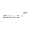
8mm Tape Drive Installation and User's Guide Note Before you install this product and use this information, be sure to read the product warranties and notices information included with the system unit into which you are installing the product. First Edition (November 1997) The following paragraph does not apply to the United Kingdom or any country where such provisions are inconsistent with local law: THIS PUBLICATION IS PROVIDED “AS IS” WITHOUT WARRANTY OF ANY KIND, EITHER EXPRESS OR IMPLIED, INCLUDING, BUT NOT LIMITED TO, THE IMPLIED WARRANTIES OF MERCHANTABILITY OR FITNESS FOR A PARTICULAR PURPOSE. Some states do not allow disclaimer of express or implied warranties in certain transactions, therefore, this statement may not apply to you. This publication could include technical inaccuracies or typographical errors. Changes are periodically made to the information herein; these changes will be incorporated in new editions of the publication. The manufacturer may make improvements and/or changes in the product(s) and/or the program(s) described in this publication at any time, without notice. It is possible that this publication may contain reference to, or information about, products (machines and programs), programming, or services that are not announced in your country. Such references or information must not be construed to mean that these products, programming, or services will be announced in your country. Any reference to a specific licensed program in this publication is not intended to state or imply that you can use only that licensed program. You can use any functionally equivalent program instead. Requests for technical information about products should be made to your authorized reseller or marketing representative. International Business Machines Corporation 1997. All rights reserved. Note to U.S. Government Users -- Documentation related to restricted rights -- Use, duplication or disclosure is subject to restrictions set forth is GSA ADP Schedule Contract with IBM Corp. Contents Safety Information . . . . . . . . . . . . . . . . . . . . . . . . . . . . . . . . . . . . Handling the 8mm Tape Drive Electrostatic Discharge Protection . . . . . . . . . . . . . . . . . . . . . . . . . . . . About This Book . . . . . . . . . ISO 9000 . . . . . . . . . . . . . . Related Publications . . . . . . . . Trademarks and Acknowledgments . . . . . . . . . . . . . . . . . . . . . . . . . . . . . . . . . . . . . . . . . . . . . . . . . . . . . . . . . . . . . . . . . . . . . . . . . . . . . . . . . . . . . . . . . . . . . . . . . . . . . . . . . . . . . . . . . . . . . . . . . . . . . . . . . . . . . . Chapter 1. Overview . . . . . . . . . . . . . . . . . . . . . . . . . . . . . . . . Front View of the 8mm Tape Drive Operating Recommendations . . . . . . . . . . . . . . . . 8mm Tape Cartridge Types . . . . . . . . . . . . . . . . . Tape Cartridge Compatibility . . . . . . . . . . . . . . . . Setting the Write-Protect Tab on 8mm Tape Cartridges Environmental Considerations for 8mm Data Cartridges Operating the 8mm Tape Drive in Harsh Environments Erasing 8mm Data Cartridge . . . . . . . . . . . . . . . . . . . . . . . . . . . . Chapter 2. Preparing to Install the 8mm Tape Drive Verifying Your Software Requirements . . . . . . . . . Checking Your Package . . . . . . . . . . . . . . . . . . Gathering Tools and Documentation . . . . . . . . . . . Planning Your SCSI Device Layout . . . . . . . . . . . Determining Your SCSI Address . . . . . . . . . . . . . . . . . . . . . . . . . . . Chapter 3. Installing the 8mm Tape Drive Setting the SCSI Address . . . . . . . . . . . Jumper Pin Positions on the 8mm Tape Drive Installing and Connecting the Tape Drive . . Configuring the 8mm Tape Drive . . . . . . . Verifying the Installation . . . . . . . . . . . . Chapter 4. Using the 8mm Tape Drive Status Lights . . . . . . . . . . . . . . . . Liquid Crystal Display . . . . . . . . . . . Changing the Display Language . . . . . Loading the 8mm Tape Cartridge . . . . Unloading the 8mm Tape Cartridge . . . Cleaning the Tape Drive . . . . . . . . . . . . . . . . . . . . . . . . . . . . . . . . . . . . . . . . . . . . . . . . . . . . . . . . . . . . . . . . . . . . . . . . . . . . . . . . . . . . . . . . . . . . . . . . . . . . . . . . . . . . . . . . . . . . . . . . . . . . . . . . . . . . . . . . . . . . . . . . . . . . . . . . . . . . . . . . . . . . . . . . . . . . . . . . . . . . . . . . . . . . . . . . . . . . . . . . . . . . . . . . . . . . . . . . . . . . . . . . . . . . . . . . . . . . . . . . . . . . . . . . . . . . . . . . . . . . . . . . . . . . . . . . . . . . . . . . . . . . . . . . . . . . . . . . . . . . . . . . . . . . . . . . . . . . . . . . . v vii vii ix ix ix ix 1-1 1-2 1-2 1-3 1-3 1-4 1-5 1-5 1-5 2-1 2-1 2-1 2-1 2-2 2-2 3-1 3-1 3-2 3-3 3-4 3-4 . . . . . . . . . . . . . . . . . . . . . . . 4-1 4-1 4-3 4-5 4-5 4-6 4-7 Contents iii . . . . . . . . . . . . . . . . . . . . . . . . . . . . . . . . . . . . . . . . . . . . . . . . . . . . . . . . . . . . . . . . . . . . . . . . . . . . . . . . . . . . . . . . . . . . . . . . . . . . . . . . . . . . . . . . . . . . . . . . . . . . . . . . . . . . . . . . . . Obtaining Additional Tape Cartridges . . . . . . . . . . . . . . . . . . . . . . . . . Appendix A. Fault Symptom Codes and Error Recovery Procedure Numbers . . . . . . . . . . . . . . . . . . . . . . . . . . . . . . . . . . . . Appendix B. Error Recovery Procedures . . . . A-1 . . . . . . . . . . . . . . . . . . . . B-1 Appendix C. Communications Statements . . . . . . . . . . . . . . . . . . Federal Communications Commission (FCC) Statement . . . . . . . . . . . . European Union (EU) Statement . . . . . . . . . . . . . . . . . . . . . . . . . . International Electrotechnical Commission (IEC) Statement . . . . . . . . . . United Kingdom Telecommunications Safety Requirements . . . . . . . . . . Avis de conformité aux normes du ministère des Communications du Canada Canadian Department of Communications Compliance Statement . . . . . . . . . . . . . . . . . . . . . . . . . . . . . . . . . . . . . . . . . VCCI Statement Radio Protection for Germany . . . . . . . . . . . . . . . . . . . . . . . . . . . Reader's Comments — We'd Like to Hear From You iv 8mm Tape Drive Installation and User's Guide 4-8 . C-1 C-1 C-2 C-2 C-2 C-3 C-3 C-3 C-4 . . . . . . . . . . . . . X-1 . . . . . . . Safety Information DANGER An electrical outlet that is not correctly wired could place hazardous voltage on metal parts of the system or the devices that attach to the system. It is the responsibility of the customer to ensure that the outlet is correctly wired and grounded to prevent an electrical shock. Before installing or removing signal cables, ensure that the power cables for the system unit and all attached devices are unplugged. When adding or removing any additional devices to or from the system, ensure that the power cables for those devices are unplugged before the signal cables are connected. If possible, disconnect all power cables from the existing system before you add a device. Use one hand, when possible, to connect or disconnect signal cables to prevent a possible shock from touching two surfaces with different electrical potentials. During an electrical storm, do not connect cables for display stations, printers, telephones, or station protectors for communication lines. Safety Information v vi 8mm Tape Drive Installation and User's Guide Handling the 8mm Tape Drive Attention: Static electricity can damage your equipment. Leave the 8mm Tape Drive in its static-protective bag until you are ready to install or configure it in your system unit. Electrostatic Discharge Protection Take the following precautions whenever you handle the tape drive or other static-sensitive devices: If you have an anti-static wrist strap, use it while handling the tape drive. Limit your movement. Movement can cause static electricity to build up around you. With the tape drive still in its anti-static bag, touch it to an unpainted metal part of the system unit, such as an expansion slot. Hold the tape drive carefully by its frame or edges. Avoid touching solder joints, pins, or other printed circuitry. Do not place the tape drive on the system unit cover or on a metal table. If you must set it aside, put it back into its anti-static bag. Before you pick it up again, touch the bag and metal frame of the system unit at the same time. Be very careful when you handle the tape drive during cold weather, as low humidity and heating increase static electricity. Handling the 8mm Tape Drive vii viii 8mm Tape Drive Installation and User's Guide About This Book This book provides information about the 8mm Tape Drive, and how to plan your SCSI device layout, set the SCSI address (also called a SCSI ID), install the tape drive, and use the tape drive. Use this book along with your specific system unit and operating system documentation. ISO 9000 ISO 9000 registered quality systems were used in the development and manufacturing of this product. Related Publications Refer to your system unit and operating system documentation for information specific to your hardware and software configuration. Trademarks and Acknowledgments AIX is a registered trademark of International Business Machines Corporation About This Book ix x 8mm Tape Drive Installation and User's Guide Chapter 1. Overview The 8mm Tape Drive is an internal streaming tape drive that provides medium to high capacity backup and archival capability and a high data transfer rate. The 8mm Tape Drive utilizes WIDE bus architecture. Communications on the SCSI bus can be either asynchronous or synchronous. The 8mm Tape Drive is read only compatible with existing 2.3GB, 5.0GB, and 7.0GB 8mm tape drives. The 8mm Tape Drive is a boot device. The tape drive is used primarily for: Saving and restoring system data files Archiving important records Distributing operating system software upgrades The drive conforms to the American National Standards Institute (ANSI) SCSI-2 standard. You can attach the drive to any system that uses a single-ended interface that meets SCSI-2 Standard ANSI X3.131-1994. The 8mm Tape Drive's features include: Use of 8mm data cartridges. Compression capability, effectively doubling the native capacity and data rate. The actual capacity per cartridge varies depending on the application and the type of data cartridge being used. Note: The factory default setting is Activated. Data compression is usually controlled by the application software. A half-high 5.25-inch form-factor. An LCD display that provides operating and error messages. Status lights that indicate: – When it is time to clean the tape drive – When the tape is in motion – When the drive is ready to accept tape motion commands Chapter 1. Overview 1-1 Front View of the 8mm Tape Drive 1 2 3 4 5 6 7 Disturbance (amber) Ready (green) Activity (green) Status lights LCD display Tape drive door Unload button Operating Recommendations Attention: Be sure to read “Handling the 8mm Tape Drive” on page vii before you remove the 8mm Tape Drive from its anti-static bag or any time you handle it. For optimum performance, always follow the recommendations listed below: Handle the drive carefully and by its external metal chassis. Keep your hands away from the printed circuit boards, components, and printed circuit (flex) cables. If possible, work on a cushioned surface, and do not drop the tape drive onto the work surface. If you move the tape drive to an environment that is colder or warmer than its previous environment, keep the drive in its package and allow the package to reach the current room temperature. This prevents potential data loss or damage to the tape drive. Allow one hour of acclimation for each 10 degrees C (18 degrees F) difference between the ship or storage temperature and the room temperature. Use only high-quality data grade 8mm tape cartridges recommended by the manufacturer (see “Obtaining Additional Tape Cartridges” on page 4-8). 1-2 8mm Tape Drive Installation and User's Guide Remove the tape cartridge from the tape drive when it is not in use, and store the cartridge in the cartridge case. Do not open the door on the data tape cartridge. This door covers and protects the magnetic tape material from dirt, dust, and damage. Avoid touching the tape, as doing so can cause loss of data. Back up any tape cartridge that repeatedly produces error messages, then discard the old tape cartridge. Error information is saved in the system error log. Clean the tape path regularly according to the cleaning procedure described in “Cleaning the Tape Drive” on page 4-7. Use only recommended cleaning cartridges. Other cleaning cartridges can permanently damage the tape drive. 8mm Tape Cartridge Types There are different types of 8mm tape cartridges that you can use for the following purposes: Type Purpose Test Tape Cartridge: Checks the operation of the drive or to run diagnostics. Do not use it to save programs or data. This cartridge, which is specially labeled, is included with the 8mm Tape Drive. Data Tape Cartridge: Saves your programs or data. This cartridge is included with the 8mm Tape Drive. Cleaning Tape Cartridge: Cleans the 8mm tape drive. See “Cleaning the Tape Drive” on page 4-7. This cartridge is included with the 8mm Tape Drive. Tape Cartridge Compatibility The 8mm Tape Drive is compatible with existing 8mm tape subsystems that comply to the American National Standard (ANSI) X3B5/89-136, Rev. 6, Helical-scan Digital Computer Tape Cartridge, 8mm for Information Exchange. Refer to the following table for information about specific tape compatibility. Chapter 1. Overview 1-3 Format Modes (C=compression mode) 8mm Tape Drive 2.3GB 2.3GB (C) 5.0GB 5.0GB (C) 7.0GB 7.0GB (C) 2.3GB Read / Write 5.0GB Read / Write Read / Write Read / Write Read / Write 7.0GB Read / Write Read / Write Read / Write Read / Write Read / Write Read / Write 20.0GB Read Only Read Only Read Only Read Only Read Only - - - - 20.0GB 20.0GB (C) - - - - - - - - - - Read / Write Read / Write Setting the Write-Protect Tab on 8mm Tape Cartridges It is necessary to set the write-protect tab on a tape cartridge so that you do not accidentally lose information. The window on the tape cartridge controls write-protection. When the window on a tape cartridge is closed, write protection is set and information can be read from the tape, but not written to it. When the window on a tape cartridge is open, write protection is not set and information can be read from the tape and written to it. 1 Window open: Write-protect tab not set 2 Window-closed: Write-protect tab set 1-4 8mm Tape Drive Installation and User's Guide Environmental Considerations for 8mm Data Cartridges This section describes operating and storage conditions including temperature, relative humidity, and maximum wet bulb data. Attention: The manufacturer specifies a set of temperature and humidity ranges in which the 8mm data cartridge can operate with ease. Only regular cleaning procedures are required when operating the cartridge within this range. The risk of possible data loss is increased if 8mm tape cartridges are operated, stored, or shipped outside the temperature or humidity ranges shown in Table 1-1. Table 1-1. Temperature and Humidity Ranges for 8mm Tape Cartridges Condition Temperature Relative Humidity (non-condensing) Maximum Wet Bulb Operating Ranges Storage Shipping 60°F-90°F (16°C-32°C) 41°F-90°F (5°C-32°C) -40°F-126°F (-40°C-52°C) 20%-80% 20%-80% 20%-80% 73°F (23°C) 79°F (26°C) 79°F (26°C) Always let a cartridge acclimate to the operating environment before you use it. Acclimation is necessary for any data cartridge that has been exposed to a different humidity environment or to a temperature change of 11°C or 20°F or more. Place the cartridge, with its container, in the operating environment for as long as it has been away from the operating environment or for 24 hours, whichever is less. Operating the 8mm Tape Drive in Harsh Environments The 8mm Tape Drive is ideally suited to streaming operations rather than tape movement operations involving multiple stops and starts and random searches. You should use streaming movement whenever possible. Do not use for archiving any tape that was previously used outside the ranges specified in Table 1-1 for an extended period of time. Exposure to the new environment deteriorates the magnetic and physical strength of the tape. Do not store important data on a tape that was used outside the specified ranges. For reliable archiving, transfer the data to a new tape. Erasing 8mm Data Cartridge Most bulk eraser devices cannot erase 8mm data cartridges. In order to properly erase an 8mm data cartridge with a bulk eraser device, the erasure rating must be at least 1500 oersted. Chapter 1. Overview 1-5 1-6 8mm Tape Drive Installation and User's Guide Chapter 2. Preparing to Install the 8mm Tape Drive This chapter covers all the things you need to do before you install your 8mm Tape Drive. Preparing to install the tape drive involves the following tasks: Verifying your software requirements Making sure your package is complete Gathering tools and documentation Planning your SCSI device layout Determining your SCSI address Verifying Your Software Requirements The 8mm Tape Drive is supported on several operating systems, including AIX 4.1.5, 4.2, or later. Please ensure that your operating system supports this tape drive before you install it. Contact your customer representative for assistance. Checking Your Package Check that your package contains the following items: The 8mm Tape Drive A 16-bit to 8-bit SCSI internal interposer (on selected kits) Media kit containing: 1 data cartridge 1 cleaning cartridge 1 test tape Contact the place of purchase if an item is missing or damaged. Gathering Tools and Documentation To install the 8mm Tape Drive, you need the following items: A flat-blade screwdriver Your system unit documentation, including any service documentation Your operating system documentation Chapter 2. Preparing to Install the 8mm Tape Drive 2-1 Planning Your SCSI Device Layout SCSI devices are attached in a daisy-chain configuration to a SCSI adapter inside your system unit. SCSI devices can be installed inside your system unit or connected externally. When you connect more than one SCSI device, it is important that you plan the layout of your SCSI chain. Each device in the chain has a unique SCSI address (also called a SCSI ID). A terminator is required at each end of the SCSI chain. Determining Your SCSI Address Before you install the 8mm Tape Drive, you must set the SCSI address on the drive. First, you must determine which SCSI addresses are available to use. Then you choose an address and install jumpers on the drive to set the selected address. You can use any available SCSI address as long as you make sure that no two SCSI devices on the same chain use the same address. No device can use address 7, which is reserved for the SCSI adapter. SCSI addresses are in sequential order from highest to lowest priority. Refer to Table 2-1 on page 2-3 for the priority associated with each address. All SCSI devices can use SCSI addresses 6 through 0. If your system unit and adapter support the wide (16 data bit, 68 conductor cable) SCSI interface, your SCSI device can also use SCSI addresses 8 through 15. To find an available SCSI address: 1. At a system prompt, type: lsdev -Cs scsi then press Enter. The following information displays: Column Column Column Column 1: 2: 3: 4: device name (for example, scsið) device status (for example, Available) SCSI location code (the format is: nn-nn-nn-a,l) device type (for example, CD-ROM drive, 2.3GB tape drive, etc.) The a in the nn-nn-nn-a,l string returned in Column 3 is the SCSI address of the device name displayed in Column 1. The l is the LUN. 2. Find an available SCSI address for the tape drive and choose the highest-priority unused address for yours. On Table 2-1 on page 2-3, record the address you picked for your 8mm Tape Drive and the names and address of any other installed SCSI devices. Save this information for future reference. 2-2 8mm Tape Drive Installation and User's Guide Table 2-1. Data Access Priorities for SCSI Addresses Priority SCSI Address Highest Priority 7 ↓ 6 ↓ 5 ↓ 4 ↓ 3 ↓ 2 ↓ 1 ↓ 0 ↓ 15 ↓ 14 ↓ 13 ↓ 12 ↓ 11 ↓ 10 ↓ 9 Lowest Priority 8 SCSI Device Name Adapter Chapter 2. Preparing to Install the 8mm Tape Drive 2-3 2-4 8mm Tape Drive Installation and User's Guide Chapter 3. Installing the 8mm Tape Drive This chapter takes you through the steps of installing your 8mm Tape Drive, which involves the following tasks: Setting the SCSI address Installing the tape drive in your system unit Connecting the tape drive Configuring the tape drive Verifying installation Setting the SCSI Address The 8mm Tape Drive is shipped with four factory-installed jumpers. After you choose an available SCSI address, you can install the jumpers on the tape drive to match the selected address. Refer to “Determining Your SCSI Address” on page 2-2 if you need instructions for selecting the SCSI address. To set a SCSI address, insert jumper pins onto pin positions reserved on the jumper block specifically for setting the address. To set a position to On, insert a jumper onto both the top and bottom pins. To set a position to Off, either insert a jumper onto the top pin only or remove the jumper from the jumper block. Refer to the figure on page 3-2 and to Table 3-1 on page 3-3 as you go through the following steps to set the SCSI address on your 8mm Tape Drive: Attention Be sure to read the handling instructions in “Handling the 8mm Tape Drive” on page vii before you begin. 1. Remove the tape drive from its anti-static bag. 2. Find pin positions 1-2, 3-4, 5-6, and 7-8, located on the jumper block on the back of the tape drive. These positions are always used to set the SCSI address on the 8mm Tape Drive. The figure on page 3-2 shows the SCSI address set to 15. 3. Refer to Table 3-1 on page 3-3 to determine in which positions you install the jumpers to correctly set the SCSI address you chose in step 2 on page 2-2. Chapter 3. Installing the 8mm Tape Drive 3-1 Jumper Pin Positions on the 8mm Tape Drive 1 68-pin SCSI connector 2 SCSI address block 3 Power connector Note: The 8mm Tape Drive is shipped with jumpers installed in the positions shown here (set to address 15). 3-2 8mm Tape Drive Installation and User's Guide Table 3-1. SCSI Address Settings SCSI Address Position 7-8 Position 5-6 Position 3-4 Position 1-2 0 Off Off Off Off 1 Off Off Off On 2 Off Off On Off 3 Off Off On On 4 Off On Off Off 5 Off On Off On 6 Off On On Off 7 Off On On On 8 On Off Off Off 9 On Off Off On 10 On Off On Off 11 On Off On On 12 On On Off Off 13 On On Off On 14 On On On Off 15 On On On On Installing and Connecting the Tape Drive After you set the SCSI address on your drive, you can install it in your system unit. Follow the instructions provided in your system unit documentation for shutting down your system and for installing an internal device in your system unit. To install and connect the 8mm Tape Drive: 1. Remove the covers to your system unit following the instructions provided in your system unit documentation. 2. Install the tape drive following the instructions provided in your system unit documentation for installing devices. 3. If the cable to attach the tape drive has a 50-pin connector, connect the 16-bit to 8-bit SCSI internal interposer (provided in your package) to the tape drive. 4. Attach the appropriate narrow or wide (50-pin or 68-pin) connector to the tape drive. Chapter 3. Installing the 8mm Tape Drive 3-3 5. If you are using the 50-pin connector, attach the tape drive to the connector with the 16-bit to 8-bit SCSI internal interposer. 6. Attach the 5/12V power plug to the drive. 7. Ensure there is a SCSI terminator on the end of the cable or that a terminator is supplied by the last SCSI device on the internal chain. 8. After the tape drive is installed, reinstall your system unit covers. Follow the instructions provided in your system unit documentation. Configuring the 8mm Tape Drive To configure the tape drive after installation, reboot your system unit. Device drivers are provided in AIX and other operating systems that support the 8mm Tape Drive. Your operating system should recognize the drive and should automatically update your system unit configuration. Verifying the Installation See the instructions provided in your operating system documentation for verifying the successful installation of the 8mm Tape Drive. To verify the installation on an AIX system, type: lsdev -Cs scsi then press Enter. A list of SCSI devices displays. An Available status indicates that the drive is installed and ready to use. 3-4 8mm Tape Drive Installation and User's Guide Chapter 4. Using the 8mm Tape Drive This chapter provides information about operating, using, and maintaining your 8mm Tape Drive. Status Lights The 8mm Tape Drive has two green status lights and one amber status light. The on and off combinations of the status lights indicate the current condition of the tape drive. Each of the International Organization for Standards (ISO) symbols located next to a status light indicates a specific condition of the tape drive as follows: 1 2 3 4 5 6 7 Disturbance (amber) Ready (green) Activity (green) Status lights LCD display Tape drive door Unload button Table 4-1 on page 4-2 explains the meaning of the green and amber status light conditions. Chapter 4. Using the 8mm Tape Drive 4-1 Table 4-1. Status Lights on the 8mm Tape Drive Disturbance (amber) Ready (green) Activity (green) On On On Off/On Off Off A tape cartridge has been inserted, and the 8mm Tape Drive is ready to receive commands from the system. See note 2. Off/On On Off A tape cartridge has been inserted, and the 8mm Tape Drive is performing a tape load or unload operation. See note 2. Off/On Off Flashing The tape is in motion, and the 8mm Tape Drive is busy running a device operation. See note 2. Off/On On Flashing The 8mm Tape Drive has detected an internal fault that requires corrective action. See note 1. Flashing Off Off The tape path requires cleaning. Refer to “Cleaning the Tape Drive” on page 4-7. On Off or On Off or Flashing Status The power-on self-test (POST) is running or the system has issued a Reset to the drive. One of the following has occurred: The power is off. The POST has completed successfully, but no tape cartridge has been inserted. See note 2. Notes: 1. If a fault or an error condition occurs, press the unload button for approximately 15 seconds to reset the drive. If the disturbance light still flashes after the reset, contact your service representative for assistance. 2. If the disturbance light is on, cleaning is required. See “Cleaning the Tape Drive” on page 4-7. 4-2 8mm Tape Drive Installation and User's Guide Liquid Crystal Display The 8mm Tape Drive features a liquid crystal display (LCD), which is located on the front panel. The LCD displays operating and error messages. A list of the messages that display are shown in Table 4-2. Table 4-2 (Page 1 of 2). LCD Messages Reset Messages RESET The first message to appear during the power-on sequence. MODEL: Variable information about the tape drive, in this case IBM—2ðGB SUBMOD: The submodel number of the tape drive. SN: The serial number of the tape drive. CODE: The level of the tape drive’s firmware. LAST CLN: The number of hours since the last cleaning. COMPRESSION: Whether data compression is turned on (the default) or turned off. SINGLE ENDED or DIFFERENTIAL The type of SCSI input/output controller (whether single ended or differential). WIDE The type of SCSI configuration. SCSI ID: The SCSI address of the tape drive (0 through 15). LANGUAGE: The current language used on the LCD. To change the language, power the tape drive off. Press and hold the unload button immediately after turning the power back on. When the desired language displays, release the unload button. Tape Drive Status Messages READY-NOTAPE The tape drive is ready to accept a cartridge. K¯K LOADING.... The tape drive is loading the tape. K¯K READY-TAPE The tape drive successfully loaded the tape and is ready for read or write operations. K¯K ILLEGAL TAPE An unsuitable tape has been loaded and rejected. << K¯K EJECT====== EJECT PREVNT The unload button was pressed. The tape drive will eject the cartridge as soon as it finishes the current operation. The system software has issued a command to prevent the eject function. Chapter 4. Using the 8mm Tape Drive 4-3 Table 4-2 (Page 2 of 2). LCD Messages Tape Motion Messages K↑K READ+■■■■■= The tape drive is reading data. The + sign appears when the data is compressed. The boxes (■) represent the amount of tape processed (out of a total of six boxes). The = sign represents the amount of unprocessed tape. K↓K WRITE+■■■■═ The tape drive is writing data. The + sign appears when the data is compressed. K/K PROTECTED The tape drive cannot write data because the data cartridge is write-protected. K/K ILLEGAL WRT The tape drive cannot write to the type of data cartridge inserted. This message remains until a proper tape is inserted or a tape motion command is issued. >> << SEARCH■■==== SEARCH■■==== A high-speed search is in progress. << REWIND■■■=== The rewind function is in progress. K×K ERASE■===== The tape drive is erasing data on the tape. As the data is erased, the equal signs (=) change to boxes (■). Cleaning Messages KyyK CLEAN SOON The tape drive needs to be cleaned. KyyK MUST CLEAN The tape drive must be cleaned because metal particle (MP) media was used. KyyK CLEANING Cleaning is in progress. KyyK DEPLETED The cleaning tape in the cartridge is used up and the tape drive will eject it. Insert a new cleaning cartridge. Error Conditions LAST 3 ERRORS ERR 1: ERR 2: ERR 3: 4-4 xx yy zz xx yy zz xx yy zz A hardware error has occurred. The LCD displays the last three error codes, with ERR 1: xx yy zz as the most recent. xx = the fault symptom code (FSC). yy and zz = additional information for product support personnel (the information may or may not be present). To resolve the error, refer to Appendix A, “Fault Symptom Codes and Error Recovery Procedure Numbers” on page A-1. 8mm Tape Drive Installation and User's Guide Changing the Display Language The text on the 8mm Tape Drive LCD is available in several languages. To change the language: 1. Press and hold the unload button after you turn the power on to the 8mm Tape Drive or, if your system unit is already running, press and hold the unload button for approximately 15 seconds until the LCD displays RESET. Release the unload button for approximately one second, then press and hold the unload button again. 2. After the LCD cycles through all the reset messages (see Table 4-2 on page 4-3), it cycles through the available languages. When the desired language displays, release the unload button. Loading the 8mm Tape Cartridge Before loading the tape cartridge, make sure the system unit power is on and that the write-protect tab on the tape cartridge is properly set. Refer to “Setting the Write-Protect Tab on 8mm Tape Cartridges” on page 1-4. The tape drive loads the tape from the cartridge and prepares it for reading and writing. 1 Window side of tape cartridge 2 8mm tape cartridge 3 Write-protect tab To load the 8mm tape cartridge: 1. Grasp the edges of the 8mm tape cartridge with the write-protect tab toward you and the window side of the cartridge facing up. 2. Slide the tape cartridge into the opening on the front of the 8mm tape drive until the loading mechanism pulls the cartridge into the drive and the drive door closes. The ready status light (green) comes on if the load operation was successful. Chapter 4. Using the 8mm Tape Drive 4-5 The 8mm Tape Drive is ready for data operations when the tape cartridge is inserted. After the cartridge is inserted into the tape drive, the tape takes about 25 seconds to load. Commands can be entered while the tape is loading. Any commands to the tape drive start running once the tape has finished loading. Commands not requiring the tape cartridge are run immediately. Unloading the 8mm Tape Cartridge Before you perform the unload operation, make sure the power to the system unit is on. 1 2 3 4 Window side of tape cartridge 8mm tape cartridge Write-protect tab Unload button To unload and eject the tape cartridge, press the unload button. The 8mm Tape Drive rewinds the tape, then ejects the tape cartridge from the tape drive. After you press the unload button, the following actions occur: The ready status light goes off. The read/write status light flashes during the unload operation. The read/write status light goes off when the cartridge is ejected from the tape drive. The time required for a tape to rewind and unload is between 18 seconds and 3 minutes, depending on the position of the tape when you push the unload button. If a fault or an error condition occurs and you cannot eject the tape, press the unload button for approximately 15 seconds to reset the drive. If the tape cartridge cannot 4-6 8mm Tape Drive Installation and User's Guide unload and has to be removed manually from the drive, contact your service representative. Cleaning the Tape Drive Attention: Do not use video cleaning cartridges in the 8mm Tape Drive. Video cleaning cartridges can damage the tape drive. Clean the tape drive: After you use a metal particle (MP) tape and before you use an advanced metal evaporative (AME) tape When error rates exceed an acceptable level as indicated by the LED and message Every 72 hours of tape motion as indicated by the LED and message The 8mm Tape Drive counts the number of hours of tape motion. When it is time to clean the tape path, it displays the message \ \ CLEAN SOON and turns on the top status light. You must clean the tape after using metal particle (MP) media and before using advanced metal evaporative (AME) tapes. If you use MP media, the LCD prompts you to clean the tape path by displaying the message MUST CLEAN. More frequent cleaning may be required if you operate the drive in a dusty environment or in humid conditions. If you allow dust to accumulate, the drive has to perform more reads and writes. This can damage the drive or cause data loss, which can be prevented by regular cleaning. The cleaning cartridge cleans the 8mm Tape Drive 18 times before you must discard it. If you attempt to use an 8mm cleaning cartridge more than 18 times, the tape drive automatically detects the error, ejects the cleaning cartridge with the amber disturbance status light remaining on, and displays the message DEPLETED. Do not use video cleaning cartridges in your 8mm Tape Drive. The 8mm Tape Drive may be permanently damaged after using a video cleaning cartridge even a few times. Before loading the cleaning cartridge, make sure the power to the 8mm Tape Drive is on. Chapter 4. Using the 8mm Tape Drive 4-7 1 Window side of tape cartridge 2 8 mm cleaning cartridge 3 Write-protect tab To clean the tape path: 1. Grasp the edges of the 8mm cleaning cartridge with the window side of the cartridge facing up and slide it into the opening on the front of the 8mm Tape Drive until the loading mechanism pulls it into the drive. After you fully insert the 8mm cleaning cartridge into the 8mm Tape Drive, the following cleaning operations are automatically performed: The cleaning tape loads into the tape path. The message CLEANING... displays. The cleaning cycles take approximately two minutes. The tape unloads and the cleaning cartridge ejects from the tape drive upon completion of the cleaning operation. The amber disturbance status light goes off if the cleaning operation was successful. 2. Record the use of the cleaning cartridge on the cartridge. Obtaining Additional Tape Cartridges Use only tape cartridges recommended by the manufacturer in the 8mm Tape Drive. Contact your customer service representative or the place of purchase to obtain the recommended tape cartridges. 4-8 8mm Tape Drive Installation and User's Guide Appendix A. Fault Symptom Codes and Error Recovery Procedure Numbers Use Table A-1 to resolve error messages that appear on the 8mm Tape Drive LCD. 1. Determine the fault symptom code (FSC) in the error message (the first two digits in the message). For example, in error message ERR 1: AD 58 Cð, the FSC is AD. 2. Locate the FSC in Table A-1 and identify the error recovery procedure (ERP) number for that FSC. 3. Locate the ERP number in Table B-1 on page B-1, and identify the recommended error recovery procedure. Table A-1 (Page 1 of 5). Fault Symptom Codes (FSC) and Error Recovery Procedure (ERP) Numbers FSC Description ERP Number Cause 02 Invalid position for WRITE 2 – 03 Tape is write protected for WRITE 5 – 04 LEOT encountered on current WRITE 10 – 05 Operation has aborted (as requested) 11 – 06 LEOT encountered on the last WRITE 10 – 08 Compression data integrity check failed 12 100% 09 Detected LEOT during READ 10 – 0A Length mismatch on READ 15 – 0B Uncorrectable block on READ 8,6 T = 90% D = 10% 0C EOD encountered on READ 13 – 0D Filemark encountered during a READ 10 – 0E Illegal condition for READ 2 – 0F READ issued at blank tape 4 – 10 READ operation has aborted (as requested) 11 – 11 Too many permanent READ errors, cannot sync 8,6 T = 90% D = 10% 14 PEOT or PEOP encountered on a READ or VERIFY 2,8,6 – 15 Bad filemark encountered during a READ 8,6 T = 100% 16 Medium error detected during a READ 8,6 T = 90% D = 10% Appendix A. Fault Symptom Codes A-1 Table A-1 (Page 2 of 5). Fault Symptom Codes (FSC) and Error Recovery Procedure (ERP) Numbers FSC A-2 Description ERP Number Cause 17 Hardware error during a READ 12 D = 100% 18 READ decompression failed – HW error 12 D = 100% 19 READ decompression CRC failed 12 D = 100% 1C Unknown or incompatible format 14 T = 100% 1D Hit setmark on READ 10 – 26 Not at legal place to WFM 2 – 27 Tape is write protected for WFM 5 – 28 LEOT encountered during WFM 10 – 31 Setmark detected on SPACE/LOCATE 10 – 32 Filemark detected during SPACE/LOCATE 10 – 33 EOD encountered on SPACE/LOCATE 10 – 34 PEOT encountered on SPACE/LOCATE 8,6 – 35 PBOT encountered on SPACE/LOCATE 2 – 36 Format error during SPACE/LOCATE 8,6 T = 80% D = 20% 37 Uncorrectable block during a SPACE/LOCATE 8,6 T = 90% D = 10% 38 Medium error during SPACE/LOCATE 8,6 T = 80% D = 20% 3A Bad filemark during SPACE (2.3GB mode only) 3 T = 100% 3B SPACE/LOCATE has aborted (as requested) 11 – 3D Lost in space 8,6 T = 80% D = 20% 47 Incompatible medium rejected after loading 14 – 4B Illegal position for ERASE 2 – 4C Tape is write protected for ERASE 5 – 4E ERASE has aborted (as requested) 11 – 58 Hardware error during SEND DIAGNOSTIC 12 D = 100% 61 Header in wrong format when loading ucode 8,6 T = 100% 63 Control load image not valid 8,6 T = 100% 65 EEPROM load image not valid 8,6 T = 100% 66 Boot code old 8,6 T = 100% 67 Cannot program one of the memories 12 D = 100% 69 CRC in load image was not correct 8,6 T = 100% 8mm Tape Drive Installation and User's Guide Table A-1 (Page 3 of 5). Fault Symptom Codes (FSC) and Error Recovery Procedure (ERP) Numbers FSC Description ERP Number Cause 6D Read buffer command failed 12 D = 100% 71 Illegal position to format partition 2 – 72 Partitions are too big for tape 2 – 74 Partition format of tape failed 8,6 – 75 Partition format aborted 8,6 – 79 Failed position to a new partition 8,6 – 7A Partition switch aborted 11 – 8C Software hang, we are very confused 12 D = 100% 8D Software detects a hardware problem 12 D = 100% 93 Detect PEOP 10 – 94 Write Setmark failure 6 – 95 WRITE failure after retry limit exceeded 8,6 T = 70% D = 30% 96 WFM failure after retry limit exceeded 8,6 T = 70% D = 30% 97 Write EOD failure after retry limit exceeded 8,6 T = 70% D = 30% 98 Fill error, invalid BRT 12 D = 100% 99 Fill error, buffer empty 12 D = 100% 9A Deformatter interrupt timeout on search 12 D = 100% 9B Overwrite (bad readback check block type) 8,6 D = 50% T = 50% 9C Formatter interrupt timeout on WRITE 12 D = 100% 9D Permanent write error, write recovery fail 8,6 T = 70% D = 30% 9E Permanent write error rewrite threshold 8,6 T = 70% D = 30% 9F Servo zone readback check failure 8,6 T = 70% D = 30% A1 Head sync error during WRITE 8,6 D = 90% T = 10% A2 Underrun error during WRITE 12 D = 100% A3 IPORT write buffer parity error 12 D = 100% A4 DPORT WRITE parity error 12 D = 100% A5 PPORT WRITE parity error 12 D = 100% A6 IPORT READ parity error 12 D = 100% Appendix A. Fault Symptom Codes A-3 Table A-1 (Page 4 of 5). Fault Symptom Codes (FSC) and Error Recovery Procedure (ERP) Numbers FSC A-4 Description ERP Number Cause A7 DPORT READ parity error 12 D = 100% A8 PPORT READ parity error 12 D = 100% AC Servo software error 12 D = 100% AD Servo hardware error 8,6 T = 90% D = 10% AE Not tracking 8,6 T = 60% D = 40% AF EOT encountered during a motion command 2 D = 100% B0 Not tracking – loss of PLL 8,6 T = 60% D = 40% B3 LBOT WRITE failure 8,6 T = 70% D = 30% B4 LBOT ATM write failure 8,6 T = 70% D = 30% B5 Read manager could not read LBOT 8,6 T = 70% D = 30% B6 EOT encountered during buffer flush 2 – C0 Power-on reset occurred 3 – C1 Tape may have been changed 3 – C2 Mode Select parameters have changed 3 – C3 New ucode was loaded 3 – C4 Operator requested media removal 11 – C5 Incompatible media was rejected 14 – C6 Not ready, cause not known 7.3 – C7 Not ready, in process of becoming ready 3 – C8 A backup positioning command is required C9 Command requires a tape and none is loaded CA 2 – 7.3 – Log Threshold met 3 – CB Log Parameter changed 3 – CC Parameter List Length error in CDB 2 – CD Illegal Operation Code 2 – CE Invalid field or reserved bits set in CDB 2 – CF This LUN is not supported 2 – D0 Invalid field in Parameter List (Mode Data) 2 – D1 Illegal bit set in identify message 2 – 8mm Tape Drive Installation and User's Guide Table A-1 (Page 5 of 5). Fault Symptom Codes (FSC) and Error Recovery Procedure (ERP) Numbers FSC Description ERP Number Cause D2 Media removal is prevented 2 – D3 Command has mode mismatch (variable/fixed) 2 – D4 Illegal Transfer Length in CDB 2 – D6 Tried to change Mode Parms and not at LBOT 2 – D7 Can’t read medium incompatible format 14 – D8 Overlapped commands attempted bad ITL nexus 2 – DA Illegal bits set in ID message 2 – DB Cannot write to tape not AME 14 T = 100% DC Rounding has occurred 10 – DD Not ready – head synch tape 7 – DE Density not supported 2 – E0 Aborted in CDB phase, parity or other error 12 – E1 Aborted prior to Data phase, bad message 12 – E2 Aborted in Data phase, init detected error 12 – E3 Aborted in Data phase, bad message 12 – E4 Aborted after Data phase, bad message 12 – E5 Aborted after Data phase, other error 12 – E6 ABORT caused by SCSI Bus Parity Error 12 – E7 ABORT sent by initiator has been completed 12 – E8 Drive needs cleaning 1 – EA Invalid mode (2.3GB) for data compression 2 – EB Download in progress 3 – EC Log parameter overflow (recovered error) 10 – EE Service required 12 D = 100% FA Serial number invalid or blank 12 D = 100% FC Head sync value in EEPROM out of range 12 D = 100% FD EEPROM contains meaningless information 12 D = 100% Note: In the Cause column, T = Tape and D = Drive Appendix A. Fault Symptom Codes A-5 A-6 8mm Tape Drive Installation and User's Guide Appendix B. Error Recovery Procedures Use Table B-1 to resolve the error messages that appear on the 8mm Tape Drive LCD. 1. Determine the fault symptom code (FSC) in the error message. For example, in error message ERR 1: AD 58 Cð, the FSC is AD. 2. Locate the FSC in Table A-1 on page A-1 and identify the error recovery procedure (ERP) number for that FSC. 3. Locate the ERP number in Table B-1, and identify the recommended error recovery procedure. If two or more ERP codes are listed for the fault symptom code in Table A-1 on page A-1, perform the action for the first code, then perform the action for the second code, and so on. Table B-1 (Page 1 of 2). Error Recovery Procedures ERP Recommended Error Recovery Procedure Number 1 Warning Message, clean drive. 2 Application program error or user error using application. Retry operation. If this problem continues, notify application provider. 3 Reissue the failed command or command sequence. 4 Application attempted to read a blank tape. Either write to the tape or replace the tape with a tape containing data. 5 Tape is write protected and a write or erase was attempted. Either write-enable the tape or insert a write-enabled tape. Perform the following until the operation can be completed: 6 7 1. 2. 3. 4. 5. Clean the drive Retry the operation Clean the drive Replace the tape cartridge If the error persists and there is an error in the system error log, call your service representative. Insert a data cartridge into the tape drive. Perform one of the following actions: 8 9 Reset the tape drive by holding down the unload button until the RESET message appears; then release the button. Send a SCSI bus reset (a hard reset). Clean the tape drive and repeat the operation. Appendix B. Error Recovery Procedures B-1 Table B-1 (Page 2 of 2). Error Recovery Procedures ERP Recommended Error Recovery Procedure Number B-2 10 No action is necessary. 11 User has pushed the unload button. No action is required; the tape drive performed the requested operation. 12 The tape drive requires maintenance. 13 The tape drive has encountered the end of the media on a read or write operation. Mount the next tape and continue the tape operation. 14 The media type is not supported. Clean the drive and retry the operation with supported media. 15 The block size requested on the read operation does not match the block size that the tape was written at. Change the application’s block size. 8mm Tape Drive Installation and User's Guide Appendix C. Communications Statements The following statement applies to this product. The statement for other products intended for use with this product appears in their accompanying documentation. Federal Communications Commission (FCC) Statement Note: The 8mm Tape Drive has been tested and found to comply with the limits for a Class B digital device, pursuant to Part 15 of the FCC Rules. These limits are designed to provide reasonable protection against harmful interference in a residential installation. This equipment generates, uses, and can radiate radio frequency energy and, if not installed and used in accordance with the instructions, may cause harmful interference to radio communications. However, there is no guarantee that interference will not occur in a particular installation. If this equipment does cause harmful interference to radio or television reception, which can be determined by turning the equipment off and on, the user is encouraged to try to correct the interference by one or more of the following measures: Reorient or relocate the receiving antenna. Increase the separation between the equipment and receiver. Connect the equipment into an outlet on a circuit different from that to which the receiver is connected. Consult an authorized dealer or service representative for help. Properly shielded and grounded cables and connectors must be used in order to meet FCC emission limits. Proper cables and connectors are available from authorized dealers. Neither the provider nor the manufacturer are responsible for any radio or television interference caused by using other than recommended cables and connectors or by unauthorized changes or modifications to this equipment. Unauthorized changes or modifications could void the user's authority to operate the equipment. This device complies with Part 15 of the FCC Rules. Operation is subject to the following two conditions: (1) this device may not cause harmful interference, and (2) this device must accept any interference received, including interference that may cause undesired operation. Responsible Party: International Business Machines Corporation Old Orchard Road Armonk, New York 10504 Telephone: (919) 543-2193 Appendix C. Communications Statements C-1 European Union (EU) Statement This product is in conformity with the protection requirements of EU Council Directive 89/336/EEC on the approximation of the laws of the Member States relating to electromagnetic compatibility. The manufacturer cannot accept responsibility for any failure to satisfy the protection requirements resulting from a non-recommended modification of the product, including the fitting of option cards supplied by third parties. Consult with your dealer or sales representative for details on your specific hardware. This product has been tested and found to comply with the limits for Class B Information Technology Equipment according to CISPR 22 / European Standard EN 55022. The limits for Class B equipment were derived for typical residential environments to provide reasonable protection against interference with licensed communication devices. International Electrotechnical Commission (IEC) Statement This product has been designed and built to comply with IEC Standard 950. United Kingdom Telecommunications Safety Requirements This equipment is manufactured to the International Safety Standard EN60950 and as such is approved in the UK under the General Approval Number NS/G/1234/J/100003 for indirect connection to the public telecommunication network. The network adapter interfaces housed within this equipment are approved separately, each one having its own independent approval number. These interface adapters, supplied by the manufacturer, do not use or contain excessive voltages. An excessive voltage is one which exceeds 70.7 V peak ac or 120 V dc. They interface with this equipment using Safe Extra Low Voltages only. In order to maintain the separate (independent) approval of the manufacturer's adapters, it is essential that other optional cards, not supplied by the manufacturer, do not use main voltages or any other excessive voltages. Seek advice from a competent engineer before installing other adapters not supplied by the manufacturer. C-2 8mm Tape Drive Installation and User's Guide Avis de conformité aux normes du ministère des Communications du Canada Cet appareil numérique de la classe B respecte toutes les exigences du Réglement sur le matériel brouilleur du Canada. Canadian Department of Communications Compliance Statement This Class B digital apparatus meets the requirements of the Canadian Interference-Causing Equipment Regulations. VCCI Statement The following is a summary of the VCCI Japanese statement in the box above. This is a Class B product based on the standard of the Voluntary Control Council for Interference from Information Technology Equipment (VCCI). If this is used near a radio or television receiver in a domestic environment, it may cause radio interference. Install and use the equipment according to the instruction manual. When used near a radio or TV receiver, it may become the cause of radio interference. Read the instructions for correct handling. Appendix C. Communications Statements C-3 Radio Protection for Germany Dieses Gerät ist berechtigt in Übereinstimmung mit dem deutschen EMVG vom 9.Nov.92 das EG–Konformitätszeichen zu führen. Der Aussteller der Konformitätserklärung ist die IBM Germany. Dieses Gerät erfüllt die Bedingungen der EN 55022 Klasse B. C-4 8mm Tape Drive Installation and User's Guide Reader's Comments — We'd Like to Hear From You 8mm Tape Drive Installation and User's Guide Part Number: 93H4553 Overall how satisfied are you with the information in this book? Overall Satisfaction Very Satisfied Satisfied Neutral Ø Ø Ø Very Dissatisfied Dissatisfied Ø Ø How satisfied are you that the information in this book is: Accurate Complete Easy to find Easy to understand Well organized Applicable to your tasks Very Satisfied Satisfied Neutral Ø Ø Ø Ø Ø Ø Ø Ø Ø Ø Ø Ø Ø Ø Ø Ø Ø Ø Very Dissatisfied Dissatisfied Ø Ø Ø Ø Ø Ø Ø Ø Ø Ø Ø Ø Please tell us how we can improve this book: Thank you for your response. May we contact you? Ø Yes Ø No When you send comments to us, you grant us a nonexclusive right to use or distribute your comments in any way we believe appropriate without incurring any obligation to you. X-1 X-2 8mm Tape Drive Installation and User's Guide Part Number: 93H4553 Printed in U.S.A. 93H4553