1
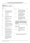
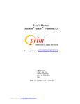
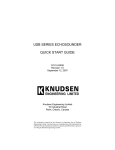
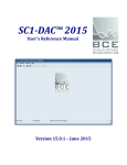
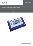
 AVIAN II(Advanced
HEARTBEAT DETECTOR ™
Vehicle Interrogation And Notification)
USERS MANUAL
Manufactured by:
For more information, please see www.Geovox.com
603 FM1092, Ste E1, Stafford, TX 77477 • Phone: 281-778-6453 • Fax: 281-778-6454
www.Geovox.com
Table of Contents
AVIAN HEARTBEAT DETECTOR™............................................................................................................................... i
AVIAN Heartbeat Detector™......................................................................................................................................... 1
Introducing AVIAN........................................................................................................................................................ 1
System Components.................................................................................................................................................. 1
Getting Started............................................................................................................................................................... 1
Starting AVIAN......................................................................................................................................................... 1
Understanding the Main Screen................................................................................................................................... 1
Shutting Down AVIAN.............................................................................................................................................. 4
The Basics...................................................................................................................................................................... 4
Inspecting a Vehicle in Regular Mode.......................................................................................................................... 4
Understanding the Insufficient Channel Warning........................................................................................................... 5
Running the Evaluate Channel Test.............................................................................................................................. 6
Troubleshooting....................................................................................................................................................... 7
Technical Support...........................................................................................................................................................8
AVIAN Heartbeat Detector™
USERS MANUAL
• Introducing AVIAN
The AVIAN Heartbeat Detector™ quickly and efficiently detects the presence of persons hidden inside vehicles of any variety. Using
data from special sensors, the AVIAN locates the shock wave generated by a human’s beating heart, which couples to any surface or
object with which the body is in contact.
The AVIAN collects data and analyzes it using advanced signal processing algorithms to detect a hidden person in less than one minute.
The system consists of an industrial-grade personal computer, standard PC operating system, custom AVIAN software, a touchscreen monitor, and sensors attached to retractable cables. The operator places the sensors on the vehicle then uses the touch-screen
to initiate a vehicle inspection. The processed data provide the operator with a PASS or SEARCH indication. The completed test can
take as little as 23 seconds after the test is initiated.
• System Components
The hardware system consists of the following:
• Industrial-grade computer
• Data acquisition/signal conditioning software and hardware
• Geophone sensors
• Optional sensor cabinet containing reel-mounted cables
The system requires 90-132 VAC or 180-264 VAC, 50-60 Hz, and consumes 70 VA of power. AVIAN is CE approved.
• Getting
Started
• Starting AVIAN
As shipped, the system is configured to automatically start with the AVIAN software upon power-up. To power up the system,
depress the black button to the ON position (top rear). If, after using the system, the program has terminated, double-clicking the
AVIAN icon on the desktop screen will restart the program. Or, the user may press the power button OFF and then ON again to restart the program.
• Understanding the Main Screen
Carefully study the picture below of the main screen of the AVIAN System. Pertinent parts are labeled and described in more detail in
the following paragraphs:
Stop Button. An operator can touch the stop button at any time to terminate a vehicle inspection. Such uses might occur if one
realizes that the wrong vehicle icon has been selected, if insufficient sensors have been placed on the vehicle, if insufficient channels
are available, or if the driver is still located in the vehicle
Regular Mode Vehicle Inspection Buttons. In Regular Mode, three vehicle icons are available to initiate AVIAN’s vehicle inspection
process. Touch the vehicle icon that most closely resembles the vehicle to be inspected. For example, use the 2-AXLE button for
passenger vehicles and other small light duty 2-axle vehicles. For 2-axle heavy-duty vehicles, use the 2HD3-Axle button. Examples of
2-axle heavy-duty vehicles include van-style delivery trucks, small box trucks and laundry trucks. Also, use the 2HD3-AXLE button
for all 3-axle vehicles such as dump trucks and garbage trucks. The 4-AXLE button is used for tractor-trailer vehicles. Note the red
dots listed on each vehicle button. These red dots indicate two requirements: a)the minimum number of sensors that must be placed
on a vehicle of this type, e. g., all four sensors must be used on a tractor-trailer. b) the minimum number of working online channels,
with sensors, that must be available to use this vehicle test button.
Quad Mode Vehicle Inspection Button. Quad Mode operation allows the Avian to test 2 or 3 or 4 vehicles simultaneously in one
inspection. All vehicles must be of the 2A type. One sensor should be properly placed on each vehicle. Any unused sensors should be placed upright on the ground. Quad Mode is activated by touching the Quad Mode icon which displays the letter Q. Notice that the
three Regular Mode vehicle test buttons now converge into one large Quad Test button. A quad test is initiated by touching the Quad
Test button. Quad Mode is exited by touching the Quad Mode icon again which returns the Avian to Regular Mode displaying the
three vehicle test buttons.
Save Data Button. Touching this icon at the conclusion of any vehicle test will immediately display the Save Current Data Set
window which is normally accessed via password and Menu selection. Data parameters may be entered as normal and saved with the
data set.
Evaluate Channel Test Button. Touching this button initiates the Channel Test procedure. See the section Running the Channel
Test below for more information.
Training Film Button. AVIAN offers a built-in live training film which demonstrates all aspects of operating the AVIAN. This film may be viewed on the screen of the AVIAN at any time by touching the Training Film button. Optional removable compact stereo speakers are provided for easy attachment to the side of the AVIAN. Volume may be adjusted with the provided slider controls. This film is a user-activated training aid that may be viewed as needed so that every operator can become familiar with the proper use of the
AVIAN
User Manual Button. For a more detailed description of the features and functions of the AVIAN, an operator may consult the builtin User Manual by touching the User Manual button. Once the Manual is opened, the operator may scroll to any desired topic and then
touch the Close button to return to the main screen. Optionally, the manual may be left open at a point of interest while the operator
returns to the main screen by touching the Return button. In this instance, the Manual remains open in the back ground which is now
indicated by an Open Book button on the Main screen. Touching the Open Book button re-displays the manual at the last point of
interest. This feature allows an operator to peruse the entire manual in any order while actively using the features of the AVIAN
program.
Search/Pass Indicator. Once an inspection is complete, this blinking bar indicates the result of the inspection by turning to a solid
color. A RED indicator with the word “Search” below it is the result for vehicles that test positive for the presence of a heartbeat
signal. A GREEN bar with the word “Pass” below it is the result for vehicles that test negative and do not have anyone in the vehicle. A YELLOW indicator is the result for insufficient data. Please see the “Inspecting a Vehicle” section below for more information.
Channel Names. Channels are named sequentially from channel #1 to channel #4 on the screen from top to bottom and in the reel
case from left to right. Each channel has a different color on the screen. The color of a channel’s respective graph on the screen also
matches the color of its name.
Channel State Indicators. These indicators display the current state of a channel. A GREEN circle indicates that the channel has
passed a Channel Test and is available for use. A RED circle indicates the channel has failed the channel test and has been disabled, or
put offline, by the system. Do not use channels with red state indicators! Those channels have failed the channel evaluation test
and should be repaired (including possible replacement of a sensor). In order to place a channel back online, it must successfully pass
the Channel Test. See “Running the Channel Test” below for more information.
Channel Signal Strength Numbers in Regular Mode. These numbers display the confidence values that each channel has detected
a heartbeat signal. They also can be used to help locate the likely position of a person hiding within the vehicle. Higher channel numbers indicate a greater probability that a person is nearer the sensor of that channel.
Channel Signal Strength Numbers in Quad Mode. When the AVIAN is operating in Quad Mode, the Signal Strength Numbers are
still shown but bear no relative connection to each other. Each number merely represents the confidence value that a heartbeat signal
has been detected on that channel.
Channel Signal Strength Bars in Regular Mode. These bars visually indicate the relative confidence levels among all channels. The scale for each channel ranges from zero to the highest reading obtained on any channel and varies with each test. The channel with the highest reading will display a full-scale bar while other channels will display bars partially filled proportionately to the highest
reading. This relationship can be used in helping to determine the likely location of a person(s) detected in a vehicle. For example, if three of the channels on a tractor-trailer read approximately one-half scale while the fourth channel reads full-scale, the person is likely
near where the sensor of the fourth channel is placed. The word “likely” is used here because other variables may factor into the
readings, such as placement of sensors on less than optimum surfaces The channel bars also display the threshold (sensitivity) values
associated with the currently selected vehicle test button.
Channel Signal Strength Bars in Quad Mode. When the AVIAN is operating in Quad Mode, The channel bars no longer show
relative strength between channels but are used only to show the Pass/Search results of each individual channel. Consequently, at the completion of a quad test, each channel bar will indicate red or green or yellow as the result status for only that channel. If any
channel bar indicates red, the Search/Pass Indicator in the upper right corner will turn red and indicate Search. If all channels show
green, the Search/Pass indicator will show green. The channel bars also display the threshold (sensitivity) values associated with the
currently selected vehicle test button.
Channel Signal Graphs. The signal graphs provide quick feedback to the operator that the channels are functional. The signal plots on the left side of the display represent signals that vary with time while the plots on the right side represent signals that vary with
frequency.
System Message Field. This field displays messages regarding the system’s operation. After a vehicle inspection, the message
displayed is of primary importance. If the inspection tests positive, then an “INTRUDER DETECTED, SEARCH” message is
displayed. Alternately, a negative test displays “No intruder detected, Pass.”
• Shutting Down AVIAN
The AVIAN system can be left on indefinitely (i. e. 24-hour operation). If desired, pressing the black on/off button will shut down the
system. Note that you do not have to exit the AVIAN program prior to shutting down the computer.
• The Basics
• Inspecting a Vehicle in Regular Mode
A vehicle inspection can be performed in a matter of minutes by the following procedure:
1. After the vehicle stops, the driver must turn off the engine, refrigeration units, etc. All known persons must get out of the
vehicle. No one should touch the vehicle during the test. Close all doors, hoods, and the trunk.
2. Place as many sensors on the vehicle as is indicated by the red dots in the appropriate vehicle icons. For example, a two-axle
delivery truck requires two sensors. Any two of the four sensors may be used as long as those channels are on-line. While
sensors may be placed on any flat surface of the vehicle, best performance is realized when the sensors are located as
close to the vehicle’s frame as possible, preferably on metal surfaces. Leaf springs and vehicle frames are excellent
locations. Try to avoid placing the sensors on the rear bumper. Pull out as much cable as needed. The cable should touch
the ground as much as possible so that it is not suspended in mid air. While inspecting a vehicle, do not place the sensor
in a location where other metal is within one inch of the top of the sensor.
3. Press the vehicle inspection button that most resembles the vehicle to be tested. The test will begin taking 10 seconds of data. The screen indicates that data is being taken with an indicator bar showing the progress.
4. If the system indicates that an intruder is present (SEARCH) and the physical inspection does not reveal anyone, repeat the test
1 to 2 additional times. If any test indicates a PASS, then you can safely pass the vehicle.
If the system indicates a person is present and the physical search locates a person, then remove the person and repeat the test. AVIAN cannot determine the number of persons present in the vehicle. Therefore, the test should be repeated until a PASS indication
is achieved.
False searches (i.e. a test results in a SEARCH when, in fact, no one is present) may result from wind, animal, and other sources of
vibration.
Note that the AVIAN may produce false search indications for unshielded wind speeds over 5 m.p.h. The reason for this is that the
vibrations produced by the wind overwhelm the heartbeat signal. Please speak with a Geovox representative for additional options for
dealing with windy conditions.
After the data is taken, several validity tests are applied to the data. If the data passes the validity tests, then analysis will follow. However, if the data fails the validity test, then another 10 seconds of data will be taken. The data may not pass the validity test
because of a gust of wind or someone brushing up against the vehicle. The automatic retaking of data may continue up to 6 times. Should this continue, the last sample of data will be analyzed regardless of the validity check.
The data analysis takes about four seconds and its progress is conveyed in the progress window. After analyzing the data, a result
indication is shown in the Search/Pass Indicator in the upper right corner of the screen as well as printed in the System Message Field
in the lower left portion of the screen. A red SEARCH indicates that the system has identified a possible intruder in the vehicle, while a
green PASS indicates that no one is in the vehicle. Note that the signal strength bars may provide an indication as to where the person
(s) are located. For instance, if the sensor of channel #1 is on the front of the vehicle while the sensor of channel #2 is on the rear,
and the greatest signal strength is registered on the front channel, then the person(s) is most likely near the front of the vehicle. The color of all four bars also will simultaneously show the color red for search and color green for pass indication.
• Understanding the Insufficient Channels Warning
The acquired data is also used to determine if a sufficient number of channels with sensors were used for the selected vehicle. If
fewer channels were available than were required, or if the channels were not functioning properly, then the Insufficient Channels
warning screen will appear. This screen is a warning that fewer channels appear to have been functioning than the number required
for the selected vehicle. Notice in the example screen below that four channels were required but only three functioning channels were
found.
The Insufficient Channels warning screen may be caused by the following conditions:
• The wrong vehicle button was selected for the vehicle being inspected.
• Fewer channels were functioning than the number required by the vehicle being inspected.
• Sensors were not properly placed upon the vehicle (perhaps tilted or side-ways).
• A channel used in the test had been placed offline by the automated CHANNEL EVALUATION test and therefor not available. A RED circle near a channel name indicates the channel is offline.
Correct any of the above problems and repeat the inspection test. However, if the problem persists, then perhaps a channel is bad. Perform a test of the channels by running the Evaluation Channel Test as described below. Repair or replace the faulty components of
any channel that fails the channel test and then repeat the channel test to verify the fault was corrected. A list of functioning channels
is also provided in the lower portion of the window.
• Running the Evaluate Channel Test
The channels should be tested on a daily basis or whenever any reason arises to suspect the integrity of the channels or sensors. Such
reasons for doubt may include dropping the sensor, changing a sensor connector, or whenever a channel used in an inspection results
in an Insufficient Channels warning screen as previously discussed. The test takes approximately 20 seconds and will automatically
disable (put offline) any channel that does not pass the test while enabling all channels that do.
To perform the test, do the following:
1.
2. 3.
4.
Place all sensors on a paved surface (concrete or asphalt) in a close proximity to each other.
After touching the Evaluate Channels icon, the following window appears prompting placement of the sensors on the ground.
Press the BEGIN TEST button to proceed. Each channel undergoes a five second test with the results shown as a GREEN
checkmark for passing the test or a RED X for failing.
If any channel fails the test at this point, repeat the Channel Test an additional time. In the event the channel fails the test again,
please replace the sensor on the failed channel with a spare sensor and repeat steps 1-3 above.
4. Press the CLOSE button after completing the test. This action will return the main screen and enable all channels that passed
the test by showing a green status circle and disable those channels that failed the test by showing a red status circle .
• Trouble Shooting
Please consult with Geovox Technical Support for guidance in correcting simple cable/sensor problems with the AVIAN equipment.
Do not attempt to repair the AVIAN computer. The most typical problem to cause a Channel Test failure is an open circuit in the
wiring somewhere between the Avian and the sensor. The last item to suspect would be the sensor. The first item to suspect would be
the cabling and/or connectors in the retractable reel. Two methods of investigation are suggested:
1.
Swap the sensor on the failed channel with the sensor on the adjacent channel and run the Channel Test
2. again and notice if the failure followed the sensor or stayed at the original channel. If the failure
followed the sensor, indications are the sensor has failed and needs to be replaced. If the failure stayed
at the original channel, the sensor was good and the problem may be in the reel. Now, repeat the
swapping procedure again but this time using a reel. If the failure followed the reel, replace the reel. If
the failure remained on the original channel, the failure is further up stream from the reel.
Test the conducting path of all sections of the cable from the sensor to the Avian with an ohm meter.
• Technical Support
For Technical Support, contact Geovox Security at any of the following
Voice: 281-778-6453 or (866) 4-GEOVOX (866-443-6869)
Fax: 281-778-6454
Email: Technical support may be obtained via e-mail at the following address:
[email protected]
A response will be issued within 24 hours.