1
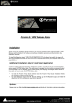
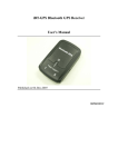
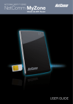
Tracker-005 GPS Tracking System
User’s Manual
HOLUX Technology, Inc.
No. 1-1, Innovation Road 1,
Science-Based Industrial Park,
Hsinchu, Taiwan
Phone :
886-3-6687000
E-Mail: [email protected]
Fax : 886-3-6687111
Web:
www.holux.com
Version : A, October, 2008
Copy right reserved by Holux Technology, Inc
Table of Contents
1.
INTRODUCTION......................................................................................................................2
2.
PACKING LIST .........................................................................................................................2
3.
BEFORE YOU GETTING STARTED ....................................................................................2
3.1.
PROCEDURE .....................................................................................................................2
3.2.
3.3.
POSSIBLE ADDITIONAL FEE ..............................................................................................2
ABOUT GPS .....................................................................................................................2
3.4.
ABOUT SIM PIN CODE & GPRS .....................................................................................2
4.
DOWNLOAD DOCUMENTS, DRIVER AND UTILITY .....................................................2
5.
SIM CARD AND BATTERY INSTALLATION .....................................................................2
6.
EZSPOT SERVICE ...................................................................................................................2
7.
USER UTILITY (TRACKER CONFIG).................................................................................2
7.1.
7.2.
7.3.
7.4.
7.5.
7.6.
7.7.
7.8.
7.9.
7.10.
7.11.
7.12.
7.13.
8.
BASIC OPERATION ................................................................................................................2
8.1.
8.2.
8.3.
8.4.
9.
INSTALLING DEVICE DRIVER ............................................................................................2
CONNECT DEVICE ............................................................................................................2
FILL PASSWORD FIELD .....................................................................................................2
READ DEVICE INFORMATION ............................................................................................2
CHANGE PASSWORD AND RESET PASSWORD ....................................................................2
REPORT PHONE NUMBER SETTING ...................................................................................2
MESSAGE REPORT TARGET ..............................................................................................2
APN SETTING ..................................................................................................................2
PHONE NUMBER SETTING ................................................................................................2
CONTINUOUS TRACKING ..................................................................................................2
SIM PIN ..........................................................................................................................2
EPO SETTING ...................................................................................................................2
MESSAGE SETTING ...........................................................................................................2
TURN ON TRACKER ..........................................................................................................2
TURN OFF TRACKER .........................................................................................................2
POSITION REQUEST ..........................................................................................................2
EMERGENCY REPORT (SOS).............................................................................................2
DISPLAY OPERATION FLOW ..............................................................................................2
9.1.
9.2.
9.3.
BUTTON FUNCTIONS .........................................................................................................2
OPERATION FLOW CHART ................................................................................................2
SCREEN EXPLANATION .....................................................................................................2
2/39
10.
TERMINOLOGY ..................................................................................................................2
11.
FAQ .........................................................................................................................................2
12.
FCC REGULATIONS ...........................................................................................................2
13.
CE DECLARATION OF CONFORMITY .........................................................................2
14.
APPENDIX A. SPECIFICATION........................................................................................2
14.1.
14.2.
PHYSICAL CHARACTERISTICS:..........................................................................................2
SYSTEM ............................................................................................................................2
14.3.
14.4.
GPRS PROTOCOL .............................................................................................................2
GSM ANTENNA ...............................................................................................................2
14.5.
14.6.
CERTIFICATION .................................................................................................................2
GSM MODULE .................................................................................................................2
14.7.
14.8.
GPS .................................................................................................................................2
POWER CONSUMPTION .....................................................................................................2
3/39
Tracker-005 User’s Guide
1. Introduction
Tracker-005 is a multi-functional tracker. Combining with GPRS and high performance
GPS, the device can be used to track and report device’s position and status to MDS. The
operation modes include continuous tracking, geophone. SOS buttons can be used to send
emergency call. All configurations can be set through SMS or USB interface. The wireless
communication includes TCP/IP, HTTP and SMS. With MTK EPO, it can get short TTFF at
distressed environment.
Application
Personal tracking
USB Connector
Power and
Back Key
Menu Key
Enter Key
SOS, Press Menu
and Enter keys
4/39
2. Packing List
Thank you for purchasing the Tracker-005 wireless GPS Tracker. Before you start,
please make sure that the following items are included in your package. If any of these
items are missing, please contact your original local HOLUX dealer or distributor.
Tracker-005 Device
Home Charger
1 Set
1 Set
USB Cable
1 CD
1 Set
1 Pcs
Quick Guide
User Manual
1 Pcs
1 Pcs
Warranty Card
1 Pcs
3. Before You Getting Started
3.1. Procedure
Make sure PIN code is unlocked before inserting the SIM card.
GPRS function should be enabled in SIM card.
PC Utility: Please install device driver “USBToCOM” before you use TrackerConfig PC
utility program.
Use TrackerConfig.exe to
- Press “Read” to see all settings in device. Please retain and keep the IMEI number
for ezSpot server registration purpose. (Reference. Sec. 7.4: Read Device
Information)
- Set tracker phone number into device.
- Set password to avoid unauthorized user access.
- Set report target: ezSpot or ezSpot server.
- Set report phone numbers. The mobile phones that can access Tracker-005. Set
report phone number 1 as SOS report phone number.
- Set APN for ezSpot server connectivity.
- If want to turn on continuous tracking mode, set the continuous tracking interval.
- Enable EPO function for better GPS performance.
For ezSpot user, install ezSpot into your mobile phone.
For ezSpot server user, go to http://ezspot.holux.com/Holux to get the latest
documents, driver, and utility. You may register using IMEI number on the label read
from Tracker Config utility. (Reference. Sec. 7.4: Read Device Information)
5/39
3.2. Possible Additional Fee
Position request and position response sent by SMS will be charged.
Each zoom operation will be charged also according to data quantity transferred.
3.3. About GPS
GPS signals are incapable of penetrating solid objects that are non-transparent. The
signals will be also be affected by surface cover such as tall buildings, tunnels,
elevated expressways, forests etc., or weather conditions such as overcast and rain. If
the vehicle is poorly insulated against heat and contains metal parts, GPS signals will
not be able to penetrate.
All wireless communication devices such as cell phones, or traffic police speed
detectors can interfere with the reception of GPS signals and results in unstable
signals.
To get position fix successfully, please hold the Holux logo up for better signal
orientation.
There is no guaranty that SOS message will be successfully sent at distressed
environment where GPS or GSM signals are weak.
3.4. About SIM PIN Code & GPRS
Notice: SIM PIN should be unlocked before being inserted into device.
SIM PIN can be disabled through ordinary mobile phone.
SIM card GPRS function enabled is required for normal operation.
If the SIM card is not inserted or SIM card is invalid, position fix function will be
disabled.
Google map installed in your cell phone will be downloaded by GPRS automatically
when ezSpot is well installed.
4. Download Documents, Driver and Utility
All related documents, driver and utility programs can be downloaded from the ezSpot
server at http://ezspot.holux.com/Holux.
5. SIM Card and Battery Installation
The battery is not pre-installed in the factory; users need to install the battery after the SIM
card is inserted. Please note the FCC label can be found in the battery compartment when
the battery lid is removed.
6/39
Tracker-005 without SIM card, battery and bottom cover
Push SIM card into SIM socket and lock the SIM socket.
7/39
Please connect battery connector to the battery socket on main board.
Put bottom cover on Tracker-005.
8/39
The final assembly of Tracker-005. Screw up the case and insert cap for water proof.
Make sure that battery is fully charged before starting operation.
6. ezSpot Service
ezSpot Service is a multi-functional Holux tracker system which includes ezSpot in
mobile phone and ezSpot server at internet. ezSpot can work with Tracker-005 and
Tracker-007 from Holux. The compatibility will be guaranteed for Holux products in the
future. There are three position report operation modes in tracker: ezSpot, ezSpot
server or both. In ezSpot mode, user can change settings in and request real-time
position from Tracker through mobile phone. For ezSpot server mode, tracker will
report position to server through HTTP. For third operation mode, tracker will report
position to both ezSpot and ezSpot server. The operation mode can be set by PC utility
program TrackerConfig through USB connection.
ezSpot server provides log history for user to view through web browser. Please
access more service from http://ezspot.holux.com/Holux/. Updated driver and utility
programs can be downloaded from ezSpot server also. Please register with email and
IMEI to get access of the server and its services.
For more information please refer to “Holux_ezSpot_User_Manual”
9/39
7. User Utility (Tracker Config)
Note: Power on Tracker-005 before plugging in USB cable and connecting with
TrackerConfig. Configurations can be set or read correctly only after system initialization
being complete.
The Tracker-005 enable users the communication with mobile phone through SMS as
default. Through this utility program, Tracker-005 can be configured to communicate with
ezSpot server through HTTP. Continuous tracking mode can be enabled to make device
getting position fix and report to server at preset interval. The APN and server domain
name can be set for internet connection. The SIM PIN can be enabled or disabled. SIM PIN
code can be changed by the utility also. The program can run only for Windows OS. No
support for Linux or Mac OS.
7.1. Installing Device Driver
Plug in Tracker-005 12-pin mini-USB cable. Please make sure you have installed the USB
to COM driver. (PL-2303 Driver Installer.exe). A new COM Port device in device manager
will appear after installation.
10/39
7.2. Connect Device
Press “Connect” button. After program connecting to the device, it will show a “Next” button
in new Diagnostic page. After pressing “Next” button the “Connect” button name will be
changed to “Close”.
11/39
If SIM card is not detected or is locked, “Ready” will not be shown on message frame.
7.3. Fill Password Field
Please fill password first before executing any command. The default password is “12345”.
7.4. Read Device information
Check Press “Read” button to retrieve all information from device. Retrieve IMEI number
and keep it for ezSpot server registration use.
12/39
7.5. Change Password and Reset Password
Press “Set” button in password group to change password.
Execute “Reset Password” button will reset password to default “12345”. This function can
be used when password is forgotten.
13/39
7.6. Report Phone Number Setting
There are 4 phone numbers that can be set. If “Enable Device Response to Any Caller” is
not checked, device will respond position request if caller phone number is in the list. If
“Enable Device Response to Any Caller” is checked, device will respond position request to
any caller.
7.7. Message Report Target
The function can be used to set parameter for report target. Tracker-005 can report position
to ezSpot in mobile phone or ezSpot server
[ezSpot]: Tracker-005 will send position to ezSpot through SMS.
[ezSpot Server]: Tracker-005 will send position to ezSpot server (or MDS) through HTTP.
[both]: Tracker-005 will send position to ezSpot through SMS and ezSpot server through
HTTP.
There are two type of “Message Report Target” :
(1) Set“Report Target” to “ezSpot”:
On SOS mode: Tracker-005 sends its position back to Phone Number phone number 1 via
short message every 5 minutes and stop after 3 successful SMS are sent.
On RING mode: When “Enable Device Response to Any Caller” is not checked (Reference.
Sec. 7.6 Report Phone Number Setting) and the phone number of the caller is one of the
preset phone numbers, then Tracker-005 will send its position back to the caller via short
message, otherwise it will not return any message to the caller. If “Enable Device Response
to Any Caller” is checked (Reference. Sec. 7.6 Report Phone Number Setting), Tracker-005
will send its position back to the caller via short message.
14/39
(2) Set“Report Target” to “ezSpot Server”:
On SOSmode: Tracker-005 sends its position back to ezSpot Server via HTTP every 5
minutes.
On RING mode: When “Enable Device Response to Any Caller” is not checked (Reference.
Sec. 7.6 Report Phone Number Setting) and the phone number of the caller is one of the
preset phone numbers, then, Tracker-005 will send its position back to the ezSpot server
via HTTP. Otherwise it will not return any information to the ezSpot server. If “Enable Device
Response to Any Caller” is checked (Reference. Sec. 7.6 Report Phone Number Setting),
Tracker-005 will send its position back to the ezSpot server via HTTP.
(3) Set “Report Target” to “both”:
On SOS mode: Tracker-005 sends its position back to Phone Number phone number 1 via
short message and its position back to ezSpot Server via HTTP every 5 minutes and stop
after 3 successful SMS are sent.
On RING mode: When “Enable Device Response to Any Caller” is not checked (Reference.
Sec. 7.6 Report Phone Number Setting) and the phone number of the caller is one of the
preset phone number, then Tracker-005 will send its position back to the caller via short
message, and send its position back to the ezSpot server via HTTP, otherwise it will not
return any message to the caller. If “Enable Device Response to Any Caller” is checked
(Reference. Sec. 7.6 Report Phone Number Setting), Tracker-005 will send its position
back to the caller via short message, and send its position back to the ezSpot server via
HTTP.
1
2
3.
15/39
7.8. APN Setting
This item is to get and set MDS server setting.
[APN]: This indicates Access Point Name
[APN User Name]: This indicates the user name for APN.
[APN Password]: This indicates the user password for APN.
[APN DNS]: This indicates the APN domain name server.
[MDS Server IP]: MDS (or ezSpot server) IP or domain name. Default is
“ezspot.holux.com”. The parameters will be set automatically by selecting Country and
Telecom. Default will be “internet”. Manual input changes are allowable if necessary.
1
2.
7.9. Phone Number Setting
[Number]: Number (MSISDN) is the phone number of SIM card in Tracker-005.
16/39
1
2
7.10. Continuous Tracking
[Continuous tracking setting]
In continuous tracking mode, Tracker-005 will report position to ezSpot server at the preset
interval.
[Interval (min)]: This is the duration, in seconds minutes, for which continuous tracking
needs to be done. The range is from 3 ~ 1440 minutes. If 0 is passed to the continuous
tracking, it will disable continuous tracking.
User can use combo box to select the interval (See red area #1), and use the “set” button to
set the setting to device. (See red area #2)
17/39
1
2
7.11. SIM PIN
SIM PIN can be locked or unlocked through “SIM Card” function. SIM PIN code can also be
changed. It is recommended to set SIM PIN in unlock mode to prevent SIM card from
entering locked state.
18/39
7.12. EPO Setting
EPO data can speed up TTFF at weak GPS environment. User can enable or disable this
function. Device will update EPO data while EPO period is expired.
7.13. Message Setting
User can set 10 set custom phone numbers and 10 set custom message settings.
These settings will be stored in Tracker-005. These settings is used for user to select
custom message and custom phone number to send out.
19/39
20/39
8. Basic Operation
8.1. Turn on Tracker
Press the power key for more than 3 seconds to turn on the device. Screen will show
welcome text.
8.2. Turn off Tracker
Press the power key for 3 seconds to turn off the device.
8.3. Position Request
(1) Input “Password” and “Tracker Tel. No” for Tracker.
(2) Press “Find Now” button.
(3) Mobile phone will call Tracker.
(4) When “Enable Device Response to Any Caller” is not checked (Reference. Sec. 7.6
Report Phone Number Setting), Tracker will start position fix Tracker will process (5)(6)(7) if
caller phone number is one of the 4 phone numbers in device configuration. If “Enable
Device Response to Any Caller” is checked (Reference. Sec. 7.6 Report Phone Number
Setting), Tracker will process (5)(6)(7).
(5) Tracker will start position fix.
(6) Tracker will report the current position if position fix succeeds.
(7) Tracker will report the latest position if position fix fails.
21/39
Java phone
Key 1 is zoom out。
Mobile phone
is zoom out。
Key 3 is zoom in。
Key * change to Satellite。
Key # change to Roadmap。
is zoom in。
Switch Satellite change to
Satellite 。
Key 0 show or hide Tracker Switch Roadmap change to
number and time。
Roadmap。
show or
hide Tracker number and time。
8.4. Emergency Report (SOS)
Pressing two keys(menu key + enter key) simultaneously for more than 3 seconds will
activate SOS mode. Tracker will try to get a fix immediately and send SOS signal.
When SOS is activated, if it is in main screen (Ref. Section 9.3.2), screen will display
SOS icon.
In SOS mode, every 5 minutes it will execute positioning and reporting until out of
battery. If message report target is “ezSpot” or “Both” (Reference Sec. 7.7 Message
Report Target), it will send SMS 3 times and stop after 3 SMS are successfully sent.
When it is executing positioning and reporting, if it is in main screen (Ref. Section
9.3.2), screen will display SOS flash icon.
Depending on the message type setting, tracker will report position to ezSpot with
phone number 1, ezSpot server or both.
In SOS mode, SOS can be unlocked by pressing two keys(menu key + enter key)
simultaneously for more than 3 seconds again. SOS also can be unlocked by mobile
22/39
phone “SOS unlock” message.
If position fix fails, device will send the latest position.
SOS mode has the highest priority. Power off function is non-functional during SOS
mode.
Java phone
Java phone
Mobile phone
Mobile phone
When ezSpot in mobile phone receives tracker’s SOS message, it will display tracker’s
SOS location for 10 sec, then the Unlock SOS screen appears.
Click Unlock to unlock SOS.
Click Exit if you don’t want to unlock, the SMS screen re-appears.
23/39
9. Display Operation flow
9.1. Button functions
Introduction:
There are 3 keys on the Tracker-005: Power/Back Key, Menu Key and Enter Key.
Pressing combinations perform these functions:
(1) Tap Power/Back Key (return functions): to return to the last page or the main menu.
(2) Press and hold Power/Back Key (on/off): to turn the Tracker on or off.
(3) Tap Menu Key (menu and select function): to enter the main menu or select function
items.
(4) Tap Enter Key (enter and confirm): to enter or confirm a function.
(5) Press and hold Menu Key + Enter Key (SOS function): to signal SOS.
9.2. Operation Flow Chart
Note: The setting in the flow chart is reference setting. It is not the default setting.
24/39
25/39
9.3. Screen Explanation
9.3.1.Welcome Screen
Introduction: this menu displays the welcome message. The first row displays the
company name; the middle row displays the Tracker's name, and the last row displays the
firmware version number.
9.3.2.Main Screen
Introduction: this screen displays the current local date and time, GSM signal strength,
SIM card exist status, battery level, new message notification and GPS status. The images
on the screen are explained below:
Represents the signal strength of GSM. The level range is 0~5.
Represents the SIM card exist status. If SIM card exists, it will show this icon.
Represents the battery level. The level range is 0~5. If battery is too low, this icon will
flash for warning.
Represents new message received or there are unread messages.
Represents
SOS mode. If SOS is positioning and reporting, this icon will flash.
The GPS icon on upper right hand corner of the screen represents the status of the last
positioning.
Represents the latest positioning was successful.
Represents the latest positioning was not successful.
Button actions:
Menu Key: enter main menu.
Enter Key: (no action)
Back Key: (no action)
9.3.3.Main Menu
26/39
Introduction: this screen displays the main menu. It has 3 primary function modules: GPS
information, message function and module configuration function. The functions
represented on the screen are explained below:
Represents GPS information module
Represents message function module
Represents module configuration function module
Button actions:
Menu Key: select module function.
Enter Key: enter module function.
Back Key: back to the main menu.
9.3.4.GPS - GPS Menu
Introduction: This screen displays the GPS function, currently there are 2 primary
functions: last fix information and turn on GPS.
Button actions:
Menu Key: Scroll down and select items.
Enter Key: Go to selected screen.
Back Key: Go back to the main menu.
9.3.5.GPS - Last Fixed Information – Date/Time
(when there is no fixed data since device power on)
(when there is fixed data since device power on)
Introduction: this screen displays the date and time of the last successful positioning.
Button actions:
Menu Key: Go back to the previous screen: [Last Fixed Information – Altitude/Speed].
Enter Key: Go to the next screen: [Last Fixed Information - Position].
Back Key: Go back to the GPS menu.
27/39
9.3.6.GPS - Last Fixed Information - Position
(when there is no fixed data since device power on)
(when there is fixed data since device power on)
Introduction: this screen displays the position of the last successful positioning.
Button actions:
Menu Key: Go back to the previous screen: [Last Fixed Information – Date/Time].
Enter Key: Go to the next screen: [Last Fixed Information – Altitude/Speed].
Back Key: Go back to the GPS menu.
9.3.7.GPS - Last Fixed Information – Altitude/Speed
(when there is no fixed data since device power on)
(when there is fixed data since device power on)
Introduction: this screen displays the altitude and speed of the last successful positioning.
Button actions:
Menu Key: Go back to the previous screen: [Last Fixed Information – Position].
Enter Key: Go to the next screen: [Last Fixed Information – Date/Time].
Back Key: Go back to the GPS menu.
9.3.8.GPS - GPS Position
(GPS not fixed)
(GPS fixed)
Introduction: this screen displays the current GPS location information. The first row
28/39
displays latitude and the second row displays longitude.
Button actions:
Menu Key: Go back to the previous screen: [Latest GPS positioning date and time].
Enter Key: Go to the next screen: [GPS location information].
Back Key: Go to the GPS menu.
9.3.9.GPS - Altitude/Speed
(GPS not fixed)
(GPS fixed)
Introduction: this screen displays the current GPS altitude and speed.
"Altitude" represents altitude information, with meter as its unit.
"Speed" represents speed information, with km/hr as its unit.
Button actions:
Menu Key: Go back to the previous screen: [GPS location information].
Enter Key: Go to the next screen: [direction of GPS compass].
Back Key: Go back to the GPS menu.
9.3.10. GPS - Compass
(GPS not fixed)
(GPS fixed)
Introduction: this screen displays the easy compass that displays the current forward
direction. The number on the left displays the actual angle and the range of the angle is 0 ~
359.
Note: the direction information is only valid when the device is on moving condition.
Button actions:
Menu Key: Go back to the previous screen: [altitude and speed information for GPS].
Enter Key: Go to the next screen: [satellite signal strength for GPS].
29/39
Back Key: Go back to the GPS menu.
9.3.11. GPS - GPS Signal Strength
(no GPS signal)
(GPS not fixed, and not used)
(GPS not fixed, but used)
(GPS fixed and used)
Introduction: this screen displays the current GPS satellite signal strength C/N value
information, currently it displays the satellite ID numbers and values for 5 satellites with the
5 strongest C/N values. The numbers in the bottom row represent the satellite ID numbers
for satellites, the bars in the middle row represent the strength of satellite signals and the
higher the bar, the stronger the signal. A hollow bar represents unused satellite, a
half-hollow bar shows a satellite is used but the positioning isn't successfully fixed yet and a
solid bar means the satellite is being used and the current positioning is successfully fixed.
The numbers on the upper row represent the C/N value of the satellite signal strength.
Button actions:
Menu Key: Go back to the previous screen: [GPS compass direction].
Enter Key: Go to the next screen: [the latest positioning information].
Back Key: Go back to the GPS menu.
9.3.12. GPS – Confirm Turn Off GPS
Introduction: This screen is used to confirm to turn off GPS.
Button actions:
Menu Key: Select [No] to give up turning off GPS and go back to the previous screen.
30/39
Enter Key: Select [Yes] to confirm turning off GPS and go to the GPS menu.
Back Key: (no action)
9.3.13. Message – Message Menu
Introduction: This screen displays messaging function, currently there are 2 primary
functions: reading message and sending message.
Button actions:
Menu Key: Scroll down and select items.
Enter Key: Go to selected screen.
Back Key: Go back to the main menu.
9.3.14. Message - Message Information
Introduction: this screen displays the message information including icons for read or not
read and the number and date for message sender.
The explanation for icons is below:
: The message has not been read.
: The message has been read.
Button actions:
Menu Key: Scroll down and select items.
Enter Key: Go to the next screen: [message content].
Back Key: Go back to the previous screen: [message main menu].
9.3.15. Message - Message Content
Introduction: this screen displays the message content.
Button actions:
Menu Key: Scroll down and see the rest of the message content.
Enter Key: Delete this message.
31/39
Back Key: Go back to the previous screen: [message information].
9.3.16. Message - Confirm Delete
Introduction: This screen is used to confirm the message is deleted.
Button actions:
Menu Key: Select [No] to give up deleting and Go back to the previous screen: [message
content].
Enter Key: Select [Yes] to confirm delete.
Back Key: Go back to the previous screen: [message content].
9.3.17. Message - Select Custom Message
Introduction: Select the message content to be sent on this screen.
Button actions:
Menu Key: Scroll down and select items.
Enter Key: Go to the next screen: [select the entire content of the default message].
Back Key: Go back to the previous screen: [main message menu].
9.3.18. Message - Custom Message Full Content
Introduction: This screen displays the entire content of the message being sent.
Button actions:
Menu Key: Scroll down and see the rest of the message content.
Enter Key: Go to the next screen: [select default number].
Back Key: Go back to the previous screen: [select default message content].
32/39
9.3.19. Message - Select Custom Phone Number
Introduction: Select the default phone number on this screen.
Button actions:
Menu Key: Scroll down and select items.
Enter Key: Go to the next screen: [confirm sending message].
Back Key: Go back to the previous screen: [select the entire content of the default
message content].
9.3.20. Message - Confirm Sending
Introduction: This screen is used to confirm message is sent.
Button actions:
Menu Key: Select [No] giving up sending message and Go back to the previous screen:
[select default phone number].
Enter Key: Select [Yes] to confirm message is sent.
Back Key: Go back to the previous screen: [select default phone number].
9.3.21. Message – Send Status
(The message is sending.)
(The message is sent OK.)
(The message is sent failed.)
Introduction: This screen displays message send status.
Button actions:
Menu Key: (no action)
33/39
Enter Key: Select [OK] to go to the message menu.
Back Key: (no action)
9.3.22. Setting - Setting Menu
Introduction: This screen displays the setting function, currently there are 2 primary
functions: time zone and back light.
Button actions:
Menu Key: Scroll down and select items.
Enter Key: Go to selected screen.
Back Key: Go back to the main menu.
9.3.23. Setting - Set Local Time
Introduction: This screen is used to set local time.
Button actions:
Menu Key: Change time zone information (the range of time zone is: -12 ~ +13).
Enter Key: Save time zone information and go to the next screen [Set Back Light Timer].
Back Key: Go back to the setting menu.
Note: Default time zone is +0.
9.3.24. Setting - Set Back Light Timer
Introduction: This screen is used to configure the time for the backlight to be on.
Button actions:
Menu Key: Change the time for the backlight to be on <provides these choices Always Off,
5 seconds, 10 seconds, 15 seconds, 30 seconds, 60 seconds and Always On>.
Enter Key: Save the configuration for the length of time for the backlight and go to next
screen [Set Local Time].
Back Key: Go back to the setting menu.
Note: Default back light is 10 sec.
34/39
9.3.25. Power Off
Introduction: power off process.
10.
EPO
Terminology
Extended Prediction Orbit, predicted ephemeris data specific for MTK
chip solution..
MDS
Main Data Server, device will send position information to server
through HTTP message
MTK
Mediatek Inc.
SMS
Short Message Service
TTFF
Time to First Fix
ezSpot
Service
ezSpot Service is a multi-functional Holux tracker system which
includes ezSpot in mobile phone and ezSpot server at internet.
ezSpot
ezSpot is the tracking service program running in Java and Windows
Mobiles phones.
ezSpot
server
ezSpot server is demo tracking service web site at Holux. Domain
name http://ezspot.holux.com/Holux
35/39
11.
FAQ
Question
Press POWER more
than 3 seconds, but can
not see power on screen
Solution
1.
It could be battery low, please charge the device, and
wait more than 30 seconds.
2.
If you still can not see power on screen, please contact
your distributor.
1.
2.
Please charge the device.
Put the device to open sky,and set the menu to GPS
status mode, after device get fixed, it will show correct
time and date information, please also check the time
offset setting on your device。
Incorrect time and date
3.
If you still can not get the correct time and date
information, please contact your distributor.
1.
GPS can not get fixed:
2.
1.
2.
Can not send message
back:
3.
4.
5.
Can not transfer data via
data cable:
1.
2.
3.
Put the device to open sky, and set the menu to GPS
status mode.
If you still can not get fixed, please contact your
distributor.
Please check is there any SIM card in your device.
If there is no SIM card on the device, please put a SIM
card on this device.
If there is a SIM card on the device, please check your
phone service provider to enable GPRS service for SIM
card.
Check make sure GPS can get fixed
If it still can not send message back, please contact
your distributor.
Make sure you had installed device driver on your PC.
Please go to control panel of Windows, click device
management, to see if you can find the device name on
the list.
If you still can not transfer data from PC, please contact
your distributor.
36/39
12.
FCC Regulations
This device complies with part 15 of the FCC Rules. Operation is subject to the following
two conditions: (1) This device may not cause harmful interference, and (2) this device
must accept any interference received, including interference that may cause undesired
operation.
This device has been tested and found to comply with the limits for a Class B digital
device, pursuant to Part 15 of the FCC Rules. These limits are designed to provide
reasonable protection against harmful interference in a residential installation. This
equipment generates, uses and can radiated radio frequency energy and, if not installed
and used in accordance with the instructions, may cause harmful interference to radio
communications. However, there is no guarantee that interference will not occur in a
particular installation if this equipment does cause harmful interference to radio or television
reception, which can be determined by turning the equipment off and on, the user is
encouraged to try to correct the interference by one or more of the following measures:
-Reorient or relocate the receiving antenna.
-Increase the separation between the equipment and receiver.
-Connect the equipment into an outlet on a circuit different from that to which the receiver is
connected.
-Consult the dealer or an experienced radio/TV technician for help.
Changes or modifications not expressly approved by the party responsible for compliance
could void the user‘s authority to operate the equipment.
37/39
13.
CE Declaration of Conformity
For the following equipment: Tracker-005 GPS Tracking System
Is here with confirmed to comply with the requirements set out in the Council Directive on
the
Approximation of the Laws of the Member States relating to Electromagnetic Compatibility
(2004/108/EC), Low‐voltage Directive (2006/95/EC) and the Amendment Directive
(93/68/EEC),
the procedures given in European Council Directive 99/5/EC and 2004/108/EC. The
equipment
was passed. The test was performed according to the following European standards:
EN301511 V9.0.2 2003
EN301489‐19
EN301489-7/1
Changes or modifications to this unit not expressly approved by the party responsible for
compliance could void the user's authority to operate the equipment.
This equipment complies with CE RF radiation exposure (SAR) limits set forth for an
uncontrolled
environment. This device and its antenna must not be co‐located or operating in
conjunction with
any other antenna or transmitter
38/39
14.
Appendix A. Specification
14.1. Physical Characteristics:
-
12-pin Mini-USB connector with USB virtual COM port
Dimensions:55 x 40 x 20 mm
-
Weight: 52.0 g
Keys: power, menu and enter key
-
Operation temperature: -10 °C ~ 55 °C
Storage temperature: -20 °C ~ 70 °C
-
Operatiing humidity 5 ~ 90%
Waterproof: IPX6
14.2. System
-
ARM7 CPU
Memory: MCP(8 Mbytes NOR and 4 Mbytes SRAM)
14.3. GPRS Protocol
-
GPRS class B
GPRS multi-slot class 12
14.4. GSM Antenna
-
Two band antenna: GSM850 and PCS1900 MHz
Two band antenna: GSM900 and DCS1800 MHz
14.5. Certification
-
FCC
CE
14.6. GSM Module
-
Chipset: MTK MT6223 + MT6139
14.7. GPS
-
Chipset: MTK MT3318
14.8. Power Consumption
-
Battery: Li-polymer Battery, 400 mAh
Standby time: 140 hours
Operation time: 60 hours with 15 minutes interval position fix in open sky.
39/39