1
TM
Elite 3 Active Isolation Workstation/
Active Isolation Module Instruction Manual
OPERATOR'S
MANUAL
Notes:
TM
Elite 3 Active Isolation Workstation/
Active Isolation Module Instruction Manual
© Newport Corporation
Irvine, California, USA
Part No. 23666, Rev D
IN-12971 (10-98)
Section 1 — Introduction
i
Warranty
Newport Corporation warrants the active isolators and controller to be
free of defects in materials and workmanship for a period of two years
from date of shipment. In the case of OEM applications, this warranty
period is extended to twenty-six (26) months to allow time for integration
of the isolation system into the OEM’s product and shipment to the final
end user. Workstation frames are warranted to be free from defects in
material and workmanship for a period of one year from the date of
shipment. In addition, the laminated honeycomb tops have a lifetime
performance and delamination warranty under normal use and proper
handling. If found to be defective during the warranty period, the product
will either be repaired or replaced at Newport’s option.
To exercise this warranty, write or call your local Newport representative
or contact Newport headquarters in Irvine, California. You will be given
prompt assistance and return instructions.
Repaired or replaced products are warranted for the balance of the original
warranty period or 90 days, which ever is longer.
This warranty does not apply to defects resulting from modifications or
improper use of the system or its component parts.
This warranty is in lieu of all other warranties, expressed or implied,
including any implied warranty of merchantability or fitness for a particular
use. Newport Corporation shall not be liable for any indirect, special, or
consequential damages.
ii
Contents
Section 1 — General Information .................................................... 1-1
1.0
1.1
1.2
1.3
1.4
1.5
1.6
1.7
Specifications ...................................................................................... 1-1
Introduction .......................................................................................... 1-2
Getting Started...................................................................................... 1-4
Unpacking and Inspection .................................................................. 1-4
Safety Terms.......................................................................................... 1-6
Workstation Placement........................................................................ 1-6
Warranty Information .......................................................................... 1-7
Options and Accessories .................................................................... 1-7
Section 2 — System Assembly ............................................................ 2-1
2.1
2.2
2.3
2.4
2.5
2.6
AIW Frame Installation ........................................................................ 2-1
Installing the Table Top or Customer Payload ................................ 2-1
Leveling the Frame .............................................................................. 2-2
Installing the Horizontal Damping Oil .............................................. 2-4
Installing the Controller and Cabling ................................................ 2-4
Options Installation ............................................................................ 2-7
Support Ring ........................................................................................ 2-7
Equipment Shelves .............................................................................. 2-8
Monitor Arm and Base Clamp ............................................................ 2-8
Cable Manager ...................................................................................... 2-9
Static Dissipative Table Tops............................................................ 2-10
2.7 Retro-Fitting AIM to the VH IsoStation .......................................... 2-10
Section 3 — Operation ............................................................................ 3-1
3.1
3.2
3.3
3.4
3.5
3.6
3.7
3.8
Power Up: Systems Integrated by Newport Corporation .............. 3-1
Power Up: Systems Integrated By the Customer............................ 3-2
Controller Front Panel Controls ..........................................................3-2
Technician interface to controller .................................................... 3-4
3.4.1 Setting system gains ................................................................ 3-4
Interface Connections.......................................................................... 3-7
High Voltage Safety Interlock.............................................................. 3-8
Serial Communication Connector Pin Connections ........................ 3-8
Docking Feature Alignment Procedure ..............................................3-8
Section 4 — Troubleshooting .............................................................. 4-1
4.1 Interpretation of Indicator Lights ...................................................... 4-1
4.2 Troubleshooting Tips .......................................................................... 4-1
Section 5 — Service and Maintenance .......................................... 5-1
5.1 Factory Service .................................................................................... 5-1
5.2 Service Form ........................................................................................ 5-1
5.3 Cleaning ................................................................................................ 5-2
iii
Contents
Section 6 — Spare Parts ........................................................................ 6-1
6.1 Spare Parts List .................................................................................... 6-1
Isolators: ................................................................................................ 6-1
Cables:.................................................................................................... 6-1
Controller: ..............................................................................................6-1
Section 7 — Elite 3 Firmware and Software .............................. 7-1
7.1
7.2
7.3
7.4
7.5
iv
Scope .................................................................................................... 7-1
Firmware and Software Installation into PC .................................... 7-1
Firmware Selection .............................................................................. 7-2
Firmware Downloading........................................................................ 7-3
Firmware and Software Upgrading .................................................... 7-4
List of Figures
Figure
1.1
1.2
1.3
1.4
2.1
2.2
2.3
2.4
2.5
2.6
2.7
3.1
3.2
3.3
v
Page
Isolator Module ..........................................................................................1-3
Assembly Orientation................................................................................1-5
Workstation Shelves & Support Ring ......................................................1-8
Caster Installation ......................................................................................1-9
Leveling Pad Adjustment ..........................................................................2-2
Shipping Locks ..........................................................................................2-3
Horizontal Damping Oil Installation ........................................................2-4
Elite 3 – Controller Rear Panel ................................................................2-5
Installing the Controller and Cabling ......................................................2-6
Cable Manager Installation ......................................................................2-9
Ground Strap Attachment ......................................................................2-10
Elite 3 Front Panel Controls ......................................................................3-3
Interface Software — Main Screen ..........................................................3-4
Interface Software — Gain Setting Screen ..............................................3-6
Notes:
vi
Section 1 — General Information
1.0
Specifications
System Includes:
Active Isolation Workstation (AIW):
Frame with independent leveling feet for each
leg, three (or four) Active Isolation Modules
with selection of load range, DSP (Digital Signal
Processor) controller and power supply, and a
selection of table tops and work surfaces.
Active Isolation Modules (AIM):
Three or four Active Isolation Modules with
selection of load range and DSP controller and
power supply.
Isolator Performance
Vertical: Active Isolation.
Transmissibility better than –15 dB at 1 Hz,
–30 dB at 10 Hz, –20 dB at 15 to 35 Hz,
–30 dB at frequencies over 40 Hz.
Active vertical isolator travel ±0.0004 inches.
Horizontal: Passive Isolation.
Natural frequency 1.0 Hz. Transmissibility 0
dB at ≤ 1.6 Hz rolling off at –40 dB per decade
above 1.6 Hz to –30 dB or better. Passive horizontal isolator travel ±0.125 inches.
Section 1 — Introduction
Maximum Floor Motion
Vertical floor motion: Less than 20 microns
peak to peak from DC to 200 Hz.
Horizontal floor motion: Less than 500 microns
peak to peak at any frequency.
Power Requirements
90-250 vac, 50-60 Hz, 4 amps max
Recommended
Operating Load
Load must be matched to isolators for optimum
performance.
Standard Load
25–250 lb. (11–120 kg) per isolator.
Heavy Load
250–500 lb. (114–227 kg) per isolator.
Docking System
Control Options
Push button from controller front panel.
TTL level interface from customer system
controller through sync connector on rear panel.
Docking Accuracy
< ±0.002 inches (0.05 mm)
1-1
1.1
Dock/Undock time
< 0.75 sec to actuate.
Settling time after undock is a function of
system leveling. Time is < 100 ms seconds for a
perfectly leveled system.
Shipping Locks
Integral with Isolation Modules. 3 ⁄ 16 inch Allen
wrench implementation. Rated at >1 g horizontal
with maximum per isolator load of 500 lb.
(227 kg).
Vertical deflection
under changing loads
Less than 0.0002 inches per lb. of load change at
nominal operating load.
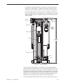
Isolator Module Size
12.00 high x 4.00 x 4.00 inches nominal overall.
See figure 1.1.
Controller Size
11.13 wide x 6.50 high x 16.82 deep
Controller Mounting
On edge within the AIW frame, rack mount, or
bench mount as customer requires.
Front Panel Controls
On/Off, System Reset, Dock/Undock
Front Panel Indicators
Power on, Fault, Docked. See Section 4,
Troubleshooting, for complete indicator
definition.
Technician Interface
Through RS232 Interface using terminal software
supplied with each system. See Sections 3.3 and
3.3.1. Dock/Undock is customer controllable
through both the TTL Sync interface, Section
3.4, and the front panel switch. The system
responds to whichever signal is the last sensed
Operating Environment
Temperature 5-40˚C humidity 90% RH, noncondensing.
Storage Environment
Temperature -10-60˚C Humidity 90% RH, noncondensing
Introduction
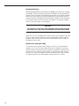
The AIW Series Active Isolation Workstation and AIM Series Active Isolation
Modules combine the best features of active and passive vibration isolation
systems. In the vertical direction geophones sense the motion of the isolator modules. The resulting velocity signal is compensated as a function
of frequency by the DSP based controller and fed back through a high
voltage amplifier to a
piezo-electric actuator which lengthens or shortens as required to cancel
ground motion. Maximum gain of the active system is at about 20 Hz.
Mounted between the geophone and the payload is a passive elastomer
isolator with a natural frequency of about 20 Hz depending on payload
weight. As the ground vibration frequency increases above 28 Hz, the elastomer isolator provides increasing isolation at the rate of –40 dB per
decade. Thus, as the active system effectiveness decreases as frequency
increases over 28 Hz, the passive isolator compensates to provide very
good overall system isolation performance.
In contrast to active isolation systems based on pneumatic isolators to
support the payload weight, the AIM/AIW Isolation system offers two
primary advantages:
1-2
• The system is relatively immune to oscillation caused by mechanical
resonances in the payload. The elastomer isolator effectively filters
out most on-board vibration before it can be sensed by the geophone.
• The isolated payload is very stiff vertically. Changes in load center of
gravity have little effect on the levelness of the payload during or after
stage movement. There is no added complexity of air isolators and air
control systems.
Shipping
Lock
Top Plate
Elastomer
Stepper
Motor
Docking
Assembly
Geophone
Piezo
12.05±.05
Unloaded
Pendulum
Oil Fill
Oil Drain
Figure 1.1 — Isolator Module
In the horizontal plane isolation is provided by a 1 Hz passive damped
pendulum system. Isolation starts at 1.4 Hz. Since most applications are
more sensitive to vertical vibration than horizontal vibration, this system
provides economical isolation suitable for most applications. Because the
pendulum has a relatively large horizontal travel, ±0.125 inches, it is well
suited for use on the upper floors of multi-story buildings where the horizontal floor motion may be many times the vertical floor motion.
For industrial applications where there is robotic transfer of parts from a
Section 1 — Introduction
1-3
non-isolated base to isolated fab or inspection stations, the AIM and AIW
offer electronically controlled docking. This system restrains the payload
horizontally, under manual or software control, during the time parts are
placed on or picked up from the isolated platform.
The Active Isolation Workstation provides an ideal working platform for
vibration influenced devices such as interferometers, microscopes, and
balances. Because of its extraordinary very low frequency isolation
capability (–15 dB @ 1 Hz) it is particularly well suited for scanning profiling
microscopy applications. Sensitive instruments such as these will show
significant improvements in resolution and repeatability when isolated
from floor motion by the AIW Active Isolation System. This versatile
workstation is available in a broad range of sizes, working surfaces,
isolator capacities, and accessory options.
Special care was taken to ensure excellent performance in the 20–50 Hz
floor vibration frequency range corresponding to dominant ambient
vibration frequencies, especially those common to multifloor buildings.
The modular isolators provide excellent protection against both vertical
and horizontal floor motions. They can be removed for service from the
Active Isolation Workstation without removing the customer payload if
provision is made to support the payload when the isolators are removed.
These workstations integrate Newport’s rigid, laminated honeycomb panel
technology and active isolation systems to provide a custom configurable
isolation system for a variety of applications. The system accommodates
high center of gravity loads with exceptional stability. Equipped with
optional casters, the system is easy to move without heavy equipment and
may be safely lifted by building elevators.
It is possible to tailor the system to a wide variety of applications using
the range of sizes and available working surfaces.
1.2
Getting Started
Please read and understand this instruction manual thoroughly before
beginning the assembly of the AIW Series Workstation. The components
have been partially assembled at the factory and only require final assembly
and performance adjustment tasks. A bubble level is provided to aid in
leveling the system.
The Active Isolation Systems on Workstations integrated at Newport
Corporation are set to a nominal gain level which is suitable for the majority
of applications. Small footprint systems where the payload is very high
may require gain adjustment to optimize performance. See Section 3.3.1.
1.3
Unpacking and Inspection
The AIW Series Workstation and AIM Active Isolation Module components
are packed in labeled boxes. Make sure the total number of delivered
boxes equals the total number listed on the labels. The components are
also labeled for better identification during assembly. Go over the assembly
orientation diagram (figure 1.2) while unpacking and verify the presence of
all ordered parts. Carefully inspect all components for any damage that
may have occurred during shipping. Report any such damage to the
shipping agent at once.
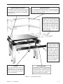
1-4
Support Ring with Armrests
The support ring encircles the top, providing
a mounting surface for shelves and support
ring mounts. Two armrests are included with
the support ring.
Equipment Shelves
One or two equipment shelves attach to the optional support
ring, providing extra storage space without transmitting
vibrations to the work surface.
Sliding Shelves
Available in 6, 10, 14 and 21-inch
widths, these durable laminated
shelves rest on the optional support ring. Be sure to order one for a
handy place to keep essential
tools, samples or documents close
at hand. Or, for maximum shelf
space, order two — one on each
side of your system.
Support Ring Mounts
Mounts may be moved
anywhere around the
support frame for secure
attachment for virtually
any type of special
equipment. A generous
array of tapped holes
on the top and side surfaces permits secure
mounting. Many customers order an extra
mount for last-minute
equipment additions.
Casters
With these heavy-duty casters, a
workstation can be quickly and
easily moved by one person.
Elite 3 is also compact enough to
fit in most elevators.
Front Support Bar
Includes two armrests for comfortable
all-day operation of equipment. Also
allows attachment of movable support
ring mount. [Note: Back support bar
without armrests also available.]
Figure 1.2 — Assembly Orientation
Section 1 — Introduction
1-5
1.4
Safety Terms
The following safety terms are used in this manual.
The term “Warning” used in the text indicates dangers that could result
in personal injury.
The term “Caution” indicates situations that may result in damage to the
AIM or AIW components.
The following International Symbols are used on the Elite 3 controllers.
Power on
Power off
Protective ground
!
Caution- refer to accompanying documentation
Alternating current
1.5
Workstation Placement
To ensure optimal performance from the AIW Series Workstation it is
necessary to consider where you place it. Attempt to locate the unit on as
level a surface as possible. Placement on an uneven floor may make
proper frame leveling more difficult. If the unit will be located on floors
other than the ground floor, attempt to place it near primary vertical
building structures such as exterior walls or support columns. This will
minimize the possibility of lower frequency floor motion affecting the
isolation performance. The active vertical isolation system may interact
with floor resonances in the 20 Hz range and may not deliver satisfactory
isolation performance. It is also advisable to avoid locations adjacent to
major sources of floor vibration such as operating machinery.
The AIW only minimally attenuates vibrations which originate on the
isolated platform. Mechanical disturbances, such as cooling fans in
equipment mounted on the isolated platform, will reduce the apparent
performance of the AIW. Likewise, because sound pressure waves impinging on the isolated platform will degrade isolation quality. Very noisy environments should be avoided.
WARNING
If installation site is susceptible to earthquakes it is recommended
that the legs be securely fastened to the floor. The Newport
Earthquake Restraint Kit can be used for this purpose. Instructions
are included with the Earthquake Restraint Kit.
1-6
1.6
Warranty Information
Warranty information may be found on the page preceding the Table of
Contents of this manual. Should it be necessary to exercise the warranty,
contact your Newport representative to determine the correct course of
action. Newport Corporation maintains offices in the United States and
worldwide. Check the back cover of this manual for the addresses and
phone numbers of these offices.
1.7
Options and Accessories
Options and Accessories for the AIW Series Workstations include the
following:
Section 1 — Introduction
Controller Support Bracket
Figure 2.5
Support Ring with Armrests
Figures 1.2 & 1.3
Support Ring Mounts
Figure 1.2
Equipment Shelves
Figures 1.2 & 1.3
Sliding Shelves
Figure 1.2
Casters
Figures 1.2 & 1.4
Clamp Kit
Not Shown
Earthquake Restraint Kit
Not shown
Elite Cleat (P/N 25177-01)
Not shown
Cable Manager
Figure 2.6
Monitor Arm
Section 2.6
Ground Strap
Figure 2.7
1-7
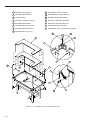
9
P/N 20389-01 Washer, neoprene
1
P/N 20387 Front uprights
2
P/N 20385 Mount brackets
10
P/N 3664-BA-244 Screw, button HD
3
P/N 21252 Brace
11
P/N 20308 Support arm bracket
4
P/N 20657 H-shaped rear frame
12
P/N 3941-JO-0905-060 Flat washer
5
P/N 20380 Shelf assembly
13
P/N 3751-AF-248 Hex head screw
6
P/N 20305 Support arm corners
14
P/N 3941-0829-048 Flat washer
7
P/N 20306 Support ring tubes
15
P/N 17054-03 Screw, hex head (thread cutting)
8 P/N 3847-BA-252 Cup pt. set
9
8
6
5
7
10
11
1
3
2
4
12
13
15
Figure 1.3 — Workstation Shelves and Support Ring
1-8
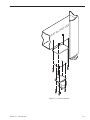
14
Figure 1.4 — Caster Installation
Section 1 — Introduction
1-9
Notes:
1-10
Section 2 — System Assembly
2.1
AIW Frame Installation
Adjust the leveling pads on the bottoms of the legs as shown in figure 2.1.
Rotate the pads until approximately 3 ⁄ 8 inch (9 mm) of thread remains outside the leg and jam nut.
If casters have been ordered, extend the leveling pads to provide floor
clearance and fasten the caster assemblies to the frame legs at the
pre-drilled and tapped locations on the lower legs (figure 1.4) using the
supplied hardware. Transfer the load to the casters by simply retracting
the leveling pads into the legs once assembly is completed. Before operating
the workstation, adjust the leveling feet as described above.
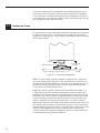
2.2
Installing the Table Top or Customer Payload
WARNING
The unloaded table top can weigh as much as 250 lb. (114 kg) and customer payloads as much as 1500 lb. (680 kg). It is important to ensure
that adequate personnel are available when installing the table top or
employ the use of a forklift or hoist
Lift the table top and carefully place it on the frame. Use a ruler to ensure
that the top is approximately centered on the frame . The AIW and AIM horizontal isolators do not incorporate a self centering device so it is necessary to keep the shipping locks engaged when placing the table top or
payload to ensure all isolators are centered and work together.
As total payload weight approaches the specified limit per isolator (250 or
500 lbs), it is critical that the payload be positioned so that the isolators
are equally loaded. In four isolator systems, the payload should be centered
over the four isolators. In three isolator systems, the payload must be
positioned off-center towards the two-isolator side of the triangle formed
by the three isolators. If any of the isolators are overloaded, the system
may drag and isolate poorly.
CAUTION
If the Isolation modules contain the docking feature, additional procedures must be followed to insure correct docking alignment.
See section 3.5 procedures
Section 2 — System Assembly
2-1
Customer payloads which are designed to be shipped in place on top of
the isolators may be secured in place using the Clamp Kit, P/N 24704-01.
The combination of Clamps and Shipping locks is designed to secure the
Top or payload to the frame and Isolators under inertial loading of at least
1g at 500 pounds static load per isolator.
2.3
Leveling the Frame
For optimum performance the AIW Frame must be leveled so that payload
or table top is horizontal. The bubble level included with the system is
generally accurate enough. If the system is not leveled, isolator horizontal
travel may be limited.
Jam nut
Height adjust nut
2.00" Nominal
(50mm)
Figure 2.1 — Leveling Pad Adjustment
2.3.1 For three isolator systems, release the shipping locks. Adjust the
four frame leveling pads (figure 2.1) until the table top is as level as can
be determined with the bubble level. Ensure that the frame does not rock
and that all four leveling pads contact the floor approximately equally.
Then, tighten the leveling pad jam nuts.
2.3.2 Four isolator systems are more critical and difficult to setup. It is
critical that the tops of the isolator modules all contact the table top or
payload at the same time and that the frame legs all contact the floor and
the frame is not twisted. Newport integrated systems consisting of frame,
isolation modules, and table top will be produced to ensure these conditions are met when the system is manufactured. In custom customer
applications adjust the base frame leveling feet so that they all contact the
floor equally and the frame is not twisted or torqued. Then, slowly lower
the payload using screw jacks until it is just above the isolator tops. Use a
0.010 inch feeler gage to ensure that the payload will contact all four
isolators equally. Shims may be installed on top of or under the isolators
to compensate for non-coplanar conditions.
2-2
2.3.3 Tighten all armrest and accessory support bolts. See Section 2.6.
Release the shipping locks. The shipping locks store by sliding them down
and securing them to the isolator bodies with the two screws in the lower
two holes. The slotted hole in the shipping lock goes at the bottom. See
Figure 2.2. Ensure that the table top is level using the standard bubble level
provided or equivalent, making any necessary further adjustments to the
four leveling pads. Ensure that the payload moves freely in all horizontal
directions. If you cannot feel free horizontal travel in all directions, first
confirm that the payload is horizontal and relevel the system if necessary.
If travel is still limited, replace all the shipping locks, jacking the payload
slightly off each isolator in turn to ensure that the shipping lock can
re-center the isolator. After the jack is removed, release the shipping
locks and recheck for free travel.
Shipping lock
in position for
transport
Shipping lock
in position for
operation
Figure 2.2 — Shipping Locks
2.3.4 Recheck that neither the frame nor the top can be rocked. If any
rocking is detected, the system must be re-leveled.
Section 2 — System Assembly
2-3
2.4
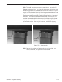
Installing the Horizontal Damping Oil
High vapor pressure damping oil, P/N 23627-01, one bottle per isolator, is
used to damp the system horizontal motion. Remove the upper “fill” plug
in the isolator body and squirt all of the oil in the plastic bottle into the
isolator. Replace the “fill” plug. See figure 2.3. Systems integrated at
Newport Corporation will generally be shipped with the damping oil
installed.
Figure 2.3 — Horizontal Damping Oil Installation
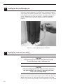
2.5
Installing the Controller and Cabling
CAUTION
To avoid damage to the controller, keep obstructions at least
2 inches (5cm) away from air ventilation slots.
CAUTION
Hazardous voltage up to 420 volts exits in the cables connecting
the isolator modules to the controller. Route these away from
traffic areas or possible damage.
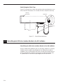
Install the Controller on the frame using the optional Controller Mounting
Bracket (see Figure 2.5) or mount the Controller at another convenient
location. Do not mount the Controller on the isolated Table Top or payload
2-4
as its fans and cables will greatly degrade isolation performance.See figure
2.4. Save the isolator cable shorting plugs in case the isolators need to be
disconnected at a future time. Connect each isolation module to the controller using the supplied cables. Attach the cables to the frame using the
supplied self adhesive pads. Neatly coil up any excess cable and secure it
in an out of the way location. The optional controller mounting bracket is
designed to facilitate storing the cables. See Figure 2.5. Newport integrated
systems will have the Isolators identified 1 through 4 at final test. Connect
their cables to the respective connectors on the controller. Isolator connectors numbered 1 and 2 on the rear panel are equipped to drive the
docking system. Isolators with docking, generally the two front isolators,
must be plugged into these connectors if they are to function. The docking lock, in docking equipped isolators, can be seen by looking down
through the .375" diameter or slotted hole in the top plate. Other than
this restriction, the isolator numbering system is not critical. Merely
select a numbering convention and continue to use it.
The Elite 3 system is equipped with a high voltage interlock which disables the high voltage power supply if an isolator cable is unplugged or
cut. on three isolator systems the supplied jumper plug must be plugged
into the “MOD 4” rear panel connector to avoid disabling the high voltage
power supply.
See Section 3 for setup of the active isolation system.
SYNC.
SIGNAL
ewport
MOD: AIC-X
S/N:
CONNECTORS
IRVINE, CA USA
FOR ISOLATORS
MODULES WITH
~
50/60 HZ
90-24VAC
OR WITHOUT
MAX 4 AMP
DOCKING
WARNING:
FOR CONTINUED PROTECTION
AGAINST FIRE RISK,
REPLACE ONLY WHITE FUSE
OF SPECIFIED RATING.
CONNECTORS
FUSE
FOR ISOLATORS
MODULES
T4A, 250V
WITHOUT
DOCKING
SERIAL
GROUND
COMM.
POST
MOD 3
MOD 4
Figure 2.4 – Elite 3 – Controller Rear Panel
Section 2 — System Assembly
2-5
(4) Mounting Screws
(4) Mounting
Screws
Figure 2.5 — Installing the Controller and Cabling
2-6
2.6
Options Installation
These additional assembly steps are necessary to install optional items
you may have ordered for your workstation.
Support Ring
WARNING
Install the support ring only after installing the table top or payload.
(see Section 2.2)
See figure 1.3.
Place the four support ring tubes (P/N 20306) in a rectangle on the floor or
workbench with the holes in the ends facing up and to the inside of the
rectangle. Slide the support arm corners (P/N 20305) into the ends of the
support tubes making sure that the three through-holes in the ends of the
tubes and the threaded holes in the corners are aligned. Install six 5 ⁄ 16 -18 x
1 ⁄ 2 -inch long button-head screws (P/N 3664-BA-244) in each corner.
Install the four support arm brackets (P/N 20308), which connect the
Active Isolation Workstation’s frame to the support ring assembly. Each
bracket is mounted to the frame with two 1 ⁄ 4 -20 x 3 ⁄ 4 -inch long hex-head
screws (P/N 17054-02). A set of five threaded holes in the frame enables
the support ring to be mounted at the level of 1", 2" or 4" thick work surfaces. Use the following list to determine which of the four threaded holes
to use:
4" thick work surface
Install the bolts finger-tight in the first and
second holes, counting from the top.
2" thick work surface
Install the bolts finger-tight in the third and
fourth holes, counting from the top.
WARNING
Two people are required to install the support ring safely.
Damage or personal injury may result from attempting to install the
support ring alone.
Turn the support ring assembly over so that the button head screw in
each corner faces down (see Figure 1.3), position each support arm corner
over a bracket, and install a 1- inch long 5 ⁄ 16 -18 hex bolt (P/N 3751-AF-248)
and washer through the bracket and into the support arm corner.
Position the support ring over the frame and tighten the eight bolts (with
washers) that connect the support brackets and the Active Isolation
Workstation frame. Place armrests (P/N 20012) on top of the support ring.
Section 2 — System Assembly
2-7
Equipment Shelves
Attach the supplied mount brackets (P/N 20385) to the two front uprights
(P/N 20387) and the H-shaped rear frame (P/N 20657) at the desired shelf
height. Place the shelves in the uprights and attach to the mount brackets.
Attach the corner braces (P/N 21252) between the rear uprights and the
top shelf, using the Phillips-head screw already installed on the underside
of the shelf to attach the corner brace (see Figure 1.3). Install the plastic
covers in the top of each of the uprights.
WARNING
Two people are required to install equipment shelves safely. Damage
or personal injury may result from attempting to install shelves alone.
Install the 5 ⁄ 16 - inch threaded studs in the corners of the support ring, then
place a rubber washer over each. Place the equipment shelf so that the
uprights cover the studs and rest on the rubber washers on the tops of
the support rail corners.
Monitor Arm and Base Clamp
The monitor arm includes a base clamp to attach it to the workstation
support rail or ring. To install a base clamp on the support ring, loosen
the hex screw on the front face and remove the retainer bar and knob by
sliding out of the side of the base clamp. To reinstall the clamp, place it
over the rail, center the retainer bar and reinstall the hex screw. Position
the clamp on the rail and then tighten the knob to lock it in place.
2-8
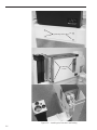
Cable Manager
The cable manager is used to minimize the vibrations transmitted by
electrical and supply cables to isolated equipment. Mount the cable
manager on the support rail or ring using a base clamp. Place cables and
supply lines between the jaws of the cable manager, maintaining as much
slack as possible on both sides of the Cable Manager. See Figure 2.6
Figure 2.6 — Cable Manager Installation
Section 2 — System Assembly
2-9
Static Dissipative Table Tops
Figure 2.7 indicates how to attach the special ground strap hardware to your
Active Isolation Workstation if it includes the static dissipative table top.
Table top
connection
Wrist band
Connection to
ground
Figure 2.7 — Ground Strap Attachment
2.7
Retrofitting the AIM Active Isolation Module to the VH IsoStation
Retrofitting the AIM Active Isolation Module to the VH IsoStation
Newport model VH IsoStation with no vibration isolation or passive
isolation can be readily retrofitted with the AIM active isolation
modules. Only conventional hand tools (screw drivers and wrenches) are required. For specific instructions on performing the retrofit, please see the instructions packaged with the retrofit kit.
2-10
Section 3 — Operation
WARNING
The possibility of electric shock may exist if the controller and isolator
modules are not grounded. All electrical plug receptacles in the
vicinity of this system should be of the grounding type and properly
polarized. Contact your electrician to check the receptacles used
to power the controller.
CAUTION
There are no user serviceable parts inside the controller. Contact
Newport Corporation if servicing is required
CAUTION
Do not connect or disconnect isolator module cables while
power is applied.
3.1
Power Up: Systems Integrated by Newport Corporation
Note: The power supply in the Elite 3 Controller will adjust automatically
for 110 or 220 volt AC operation.
Those Active Isolation Workstations integrated by Newport will isolate
effectively as they are delivered in almost all cases. Simply level the system,
remove the shipping locks, ensure that there is free horizontal travel in all
directions, plug the controller in, and turn it on. See figure 3.1. After about
35 seconds a green “Power” light will indicate that the system is functioning properly. If the red “Power” light appears refer to Section 4,
Troubleshooting, and Section 3.2, Power Up — Systems Integrated
By the Customer.
The Elite 3 Controller is electrically protected by fuses. See Section 4Troubleshooting, for specific fuse types and location.
Section 3 — Operation
3-1
3.2
Power Up: Systems Integrated By the Customer
If a red “Power” light appears, or if the system is being integrated by the
customer, system gains must be set by the customer. This is done
through the “Technician Interface” through the RS232 serial port, labeled
“SERIAL COMM,” on the rear panel.
The following equipment is required:
• PC (Pentium with Windows 95 minimum).
• Communication and Setup software and RS 232 Cable are included with
the system.
Install the software in a directory or folder of your choice. Follow the disk
label instructions and the prompts..
3.3
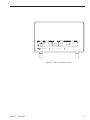
Controller Front Panel Controls
Three function are controlled from the Elite 3 front panel buttons. The system status is shown by the combination of colors of the power and the
Dock/Undock indicator lights as defined in section 4.1
“Power” button
Turns on or off AC line power to the Elite 3 system.
Either a red or a green light indicates power on.
“Reset” button
Re-initializes the controller DSP and re-starts system.
Power indicator light will turn red for about 35 seconds
while the system measures and corrects electronic offsets and ramps up isolation loop gains.
“Dock/Undock”
button
Pressing the “Dock/Undock” button toggles the system
between docked and undocked states. A green indicator light signifies undocked. A red indicator light
signifies docked.
CAUTION
Do not activate the “Dock/Undock” function more often
than once every five seconds to avoid exceeding the
allowable mechanism duty cycle.
3-2
POWER
STATUS
RESET
DOCK /
STATUS
UNDOCK
POWER ON
I
DOCKED
UNDOCKED
SYSTEM FAULT
0
NEWPORT
Active Isolation System
ELITE 3
Figure 3.1 – Elite 3 Front Panel Controls
Section 3 — Operation
3-3
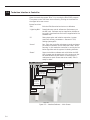
3.4
Technician Interface to Controller
Open the terminal program “Elite 3” by running the Elite 3.EXE program.
The system control functions are accessed by clicking on the buttons in
the upper left screen corner.
Button functions:
“Exit”
Exits the Elite3 terminal and returns to Windows
“Lightning Bolt”
Downloads new control software to flash memory on
the DSP card. Software may be supplied on diskette or
by e-mail. Download instructions are supplied with the
software files.
“G”
Sets system gains and isolation saturation (system
overload) recovery parameters. See section 3.3.1,
Setting system gains.
“Arrow”
Run. Exits the controller maintenance mode and starts
the isolation software. Screen status bar reads, “Elite 3
Running.” In this mode the controller is running the isolation algorithm and the system is isolating vibration.
“Reset”
Stops the isolation software and re-initializes the DSP.
Gain changes may be made now or the system can just
be restarted with the Run button. Places system in
maintenance mode. Screen status bar reads, “Elite 3
ready for data.”
Interface software version
Reset system
controller
Matches Elite 3
controller &
PC com ports
Shows firmware
currently installed
in controller
Run — starts
isolation control
Set isolation
system gains
Download
new control
software into
flash memory
Select firmware download
or gain change download
Exit Elite3
Reset and exit
Figure 3.2 — Interface Software — Main Screen
3-4
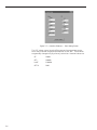
3.4.1 Setting system gains
The same gain settings are not appropriate for all payloads and environments. To maximize isolation performance, the system gains can be set to
the highest level at which the system is stable and does not oscillate. In
practice, gains should be set at least 25% below the point at which oscillation or unstable operation occurs and isolation will be near optimum.
Benign environments — those with moderate floor motion and minimal
acoustic disturbances — combined with low center-of-gravity payloads
enable the use of higher gains. Noisy environments and very high c-g payloads promote system oscillation and the gains must be set lower.
Acceptable system gains range from 0.001 (essentially 0, or a passive isolation system) to 0.99. System gains are nominally set at 0.25 on all isolator
channels at the factory. These settings will yield specified isolation performance in a typical light manufacturing area. You can assess the effects of
gain changes on your process by observing the changes in your process
as the gains are changed. Alternatively, you can measure the Elite system
transmissibility (isolated payload motion/floor motion) with a dual channel spectrum analyzer and a pair of seismic accelerometers or geophones.
To set the system gains click on the “Reset” button to put the controller in
maintenance mode. When the status bar reads “Elite 3 ready for data,”
click on the “G” button and merely change the gains on the “Transfer
Gains” screen. It is recommended that all gains be set identically except
on three isolator systems where gain number four is not used. In this case,
gain number four is set to 0.00. Non-identical gain settings are generally
appropriate only for systems with asymmetric loading and have to be
determined on an individual system basis. Set the ramp time to approximately 100 times the highest gain setting. Click the “Transfer Values” button to download the new gain settings. Exit the maintenance mode with
the “Run” button on the main menu to restart the isolation algorithm.
The computer may be disconnected at this time if desired.
Section 1 — Introduction
3-5
Figure 3.3 — Interface Software — Gain Setting Screen
The “GF” values control how the Elite recovers from transient shocks
which may overload the geophone amplifier or DSP ADC. These values
are generally changed only by a factory technician. Nominal values are:
3-6
GF
0.9999
GF2
0.99999
invGF
1.000004
GFTIX
1000.
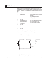
3.5
Interface Connections
The Active Isolation Module docking function is synchronized with customer equipment through the “SYNC. SIGNAL” connector on the controller
rear panel. Signals are TTL compatible. Pin outs and commands are as follows:
Pin
Function
Interpretation
1
Isolation status
6
2
7
Not used
Docking enable input
Dock / Undock input
3
8
4
9
Logic ground
Not used
Not used
Not used
5
Not used
Floating output = Elite not isolating
Vmax= 30v
Low = Isolation functioning
Imax= 50mm
(See Figure 3.4)
High input enables docking system
High causes system to dock
Low causes system to un-dock
If system power is interrupted, the docking system will remain in the
current docking condition when the power is interrupted.
Elite 3
Controller
User Interface
Circuit
1
OPTOCOUPLER
IN
+
OUT
5 – 24V
-
3
Figure 3.4 Isolation status output – recommended
user interface circuit
Section 1 — Introduction
3-7
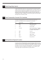
3.6
High Voltage Safety Interlock
A high voltage safety interlock is incorporated into the isolation module
cables. If any of the cables are unplugged the Elite 3 controller will turn off
the 420 volt high voltage power supply. In three isolator systems, the supplied jumper plug must be plugged into the unused module connector
(generally connector number 4) for the system to function. When the high
voltage power supply is disabled, the rest of the system is still functional
although it will not actively isolate.
3.7
Serial Communication Connector Pin Connections
The serial communication port on the controller rear panel, see
figure 2.4, is an RS232 port. Pin connections are as follows:
3.8
Pin
Signal Name
Function
1
DCD
Data Carrier Detect
2
TXD
Transmit Data
3
RXD
Receive Data
4
PC_DTR
Data Terminal Ready - Toggling
this line to high causes SBC32
to reset for remote reset.
5
GND
Ground
6
DSR
Data Set Ready
7
CTS
Clear To Set
8
RTS
Request To Send
9
Ring in
Ring Indicator
Docking Feature Alignment Procedure
To insure correct docking alignment, the payload must be lifted and reinstalled while the two docking mechanisms are engaged. Other non docking
modules should have their shipping locks temporarily installed during this
procedure so as not to lose their initial alignment. The docking modules
should also have their shipping locks attached in the up position, with
screws finger tight to prevent Isolator top plate rotation.
3-8
Section 4 — Troubleshooting
4.1
Interpretation of Indicator Lights
There are two lights on the front panel. Each has four conditions: off, red,
green, and amber. Light definition is as follows:
Power Status
Light
4.2
Dock/Undock
Status Light
Light Combination Definition
OFF
OFF
System power off
GREEN
GREEN
System operating, undocked
GREEN
RED
System operating, docked
RED
OFF
FAULT
RED
RED
FAULT
RED
AMBER
FAULT
RED
GREEN
FAULT
Troubleshooting Tips
4.2.1 Verify that the mechanical system setup is correct, see Section 2.
Ensure that all four frame feet contact the floor firmly. If one or more feet
are not firmly seated against the floor, the system will oscillate.
4.2.1 Ensure that the system is on a stiff floor (slab on grade or resonant
frequency higher than 25 Hz). The active system will not function correctly
on “soft” or wooden floors.
4.2.3 If you must operate the system on a carpeted floor, order the Elite
Cleat, P/N 25177-01, to penetrate the carpet and make a solid connection
between the frame and the floor.
4.2.4 Confirm that all cables are properly plugged in and that the jumper
plug is plugged into the “MOD 4”connector on three isolator systems.
4.2.5 Confirm that the isolator gains are properly set. See Section 3.3.1.
4.2.6 Confirm That The AC Line Fuses Have Not Blown
The Elite 3 is protected by AC line fuses located in the line cord connected
on the controller rear panel. See figure 2.4. Replace the fuses with those of
the same type and rating.
4.2.6.1 Elite 3 User Serviceable Fuses
AC line fuse, 2 required
Section 4 — Troubleshooting
Time lag (Slo-Blo) fuse, 4 amp., Type T4A,
250 V., 5 x 20 mm.
4-1
4.2.6.2 Elite 3 Non-User Serviceable Fuses
Internation power supplies, mounted on power line PCB, 2required
Time lag (Slo-Blo) fuse, 3 amp., Type
T3A, 250 V., 5 x 20 mm.
High voltage “Pacifitek” power supply, 2 required
Time lag (Slo-Blo) fuse, 0.5 amp., Type
T0.5A, 250 V., 5 x 20 mm.
4.2.7 Communications Ports
Confirm that the Elite 3 Terminal Program used to communicate with the
Elite 3 AIC Controller is configured to communicate through an available
Com Port. The Elite 3 AIC is normally configured to communicate through
Com Port 1. The Com Port can be changed with the “Com Port” pull down
menu. See figure 3.2 (Elite 3 Terminal Programs earlier than Version 3.0 are
configured to communicate through Com Port 1 only).
4.2.8 Call your Newport Technical Service Representative, 1-949-863-3144.
4-2
Section 5 — Service and Maintenance
WARNING
If the power cord or the isolator module cables show signs of
wear they should be replaced as soon as possible
5.1
Factory Service
To obtain information concerning factory service, contact Newport
Corporation or your Newport representative at 1-714-863-3144. Please
have the following information available.
1. Model number.
2. Purchase order number.
3. Complete description of the problem.
If components are to be returned to Newport Corporation, you will be
given a Return Number, which you should reference in your shipping
documents.
Please fill out the service form on the next page and have the information
ready when contacting Newport Corporation. Include the completed
service form with any parts or components that are returned.
CAUTION
Remove the horizontal damping oil from thee isolator modules through
the lower drain hole, see figure 2.3, before returning them to Newport.
Alternatively, package the isolator modules vertically on a palletized
crate prior to shipping.
5.2
Service Form
Please include a completed Service Form with all equipment returned to
Newport Corporation for service.
Section 5 — Service and Maintenance
5-1
5.3
Cleaning
To clean any of the optional work surfaces (either 400 series stainless
steel or high pressure laminate) spray household cleaner, such as “409” or
“Fantastic”, on a clean cloth and wipe down. Avoid using abrasive cleaners
since they will foul the mounting holes and also damage the laminate tops.
Powder coated frames may be cleaned in the same manner as the work
surfaces.
Do not spray liquid cleaners on the controller. If it is necessary to clean
the controller, un-plug it and wipe it with a rag dampened (not dripping)
with household cleaner. Remove the cleaner with a clean rag dampened
(not dripping) with water.
5-2
Notes:
Section 1 — Introduction
5-3
5.2
Name
Newport Corporation
U.S.A. Office: 714/863-3144
FAX: 714/253-1800
Service Form
_____________________________________________________________________________________
Company
_______________________________________________________________________________
Address
_________________________________________________________________________________
Country
_________________________________________________________________________________
P.O. Number ___________________________________________________________________________
RETURN AUTHORIZATION # ___________________________
(Please obtain prior to return of item)
Date
_______________________________________________________________
Phone Number
_______________________________________________
Item(s) Being Returned:
Model #
_______________________________________________________
Description
Serial #
________________________________________________________________________________________
________________________________________________________________________________________________________________________________________________________
Reason for return of goods (please list any specific problems)
___________________________________________________________________________
__________________________________________________________________________________________________________________________________________________________________________
Please complete the below, as appropriate.
Describe problem
______________________________________________________________________________________________________________________________________________
__________________________________________________________________________________________________________________________________________________________________________
__________________________________________________________________________________________________________________________________________________________________________
__________________________________________________________________________________________________________________________________________________________________________
__________________________________________________________________________________________________________________________________________________________________________
__________________________________________________________________________________________________________________________________________________________________________
__________________________________________________________________________________________________________________________________________________________________________
__________________________________________________________________________________________________________________________________________________________________________
__________________________________________________________________________________________________________________________________________________________________________
__________________________________________________________________________________________________________________________________________________________________________
__________________________________________________________________________________________________________________________________________________________________________
__________________________________________________________________________________________________________________________________________________________________________
__________________________________________________________________________________________________________________________________________________________________________
__________________________________________________________________________________________________________________________________________________________________________
__________________________________________________________________________________________________________________________________________________________________________
__________________________________________________________________________________________________________________________________________________________________________
__________________________________________________________________________________________________________________________________________________________________________
__________________________________________________________________________________________________________________________________________________________________________
__________________________________________________________________________________________________________________________________________________________________________
__________________________________________________________________________________________________________________________________________________________________________
__________________________________________________________________________________________________________________________________________________________________________
(Attach additional sheets as necessary).
5-4
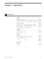
Section 6 — Spare Parts
6.1
Spare Parts List
Isolators:
Standard load, non-docking
22971-03
Standard load, docking — with round docking hole in top plate
22971-01
Standard load, docking — with slotted docking hole in top plate
22971-05
High load, non-docking
22971-04
High load, docking — with round docking hole in top plate
22971-02
High load, docking — with slotted docking hole in top plate
22971-06
Horizontal damping oil, 1 bottle per isolator
23627-01
Controller:
3 Isolator system
AIC-3
(23670-01)
4 Isolator system
AIC-4
(23670-02)
Cables:
Power line cord
04583-00
Technician interface, RS232 serial communication
25101-01
Isolator cable extension —18"
24456-01
36"
24456-02
54"
24456-03
Accessories:
Section 6 — Spare Parts
Caster Kit
25271-01
Cleat Kit
25177-01
6-1
Notes:
6-2
Section 7 - Elite 3 Firmware and Software
7.1
Scope
This manual section describes the firmware version 2.0 and software version 3.0. Any future revisions will be described in the "Read me" files
included on the diskettes supplied with the Elite 3 system. Firmware and
software enhancements and revisions will be described in detail in "Read
me" files included on any upgrade diskettes.
7.2
Firmware and Software Installation into PC
A PC and RS 232 cable as described in Section 3.2 are required.
The Elite 3 firmware and software are provided on two 3.5" diskettes.
To install, follow the instructions on the disks' labels. Before installation
of new software rename the directory where existing Elite 3 interface
software resides. Make sure new software is installed in a different
directory to avoid over writing prior versions. The setup program will
install the software and firmware in the default directory
C:\ProgramFiles\Elite3 or other user defined directory. The directory
will contain two groups of files:
Windows Utility Interface Software version 3.0
Elite3.exe
Imghook.dll
Install.log
Unwise.exe
Firmware version 2.0
2_0fr212.a0
2_0fs220.a0
2_0std21.a0
Section 7 — Firmware and Software
7-1
7.3
Firmware Selection
Elite 3 controllers are factory programmed with the standard firmware
(file 2_0std21.a0) and fully operational as received. It is not necessary to
download any firmware prior to operation.
Firmware files provided on the diskettes offer different control algorithms
which may be downloaded by the user. The different control algorithms
may improve the system isolation performance depending on the type of
vibration environment in which the system operates.
Below are the guidelines for selecting the firmware file (control algorithm)
applicable to your operating environment:
2_0std21.a0 - "standard" algorithm downloaded at the factory. This control algorithm provides best isolation performance under most typical
floor conditions.
2_0fr212.a0 - "fast recovery" algorithm. This firmware provides improved
stability and faster recovery time from large disturbances caused by
excessive floor motion or payload disturbances. It is most suitable for
environments containing large low frequency (=< 3Hz) floor displacements. These large amplitude low frequency motions may exceed the
allowable floor motion level (see Section 1.0) and overdrive the system.
This firmware reduces the chance of overdriving the system and provides
faster recovery from such events than the standard firmware. In terms of
isolation performance, this firmware is almost identical to the standard
one. There is less than 5 dB performance degradation at one Hz.
2_0fs220.a0 - "fast settling" algorithm. This algorithm provides the shortest settling time after large disturbances. It is the most robust firmware of
the three provided and is suitable for floor environments where large disturbances exceeding the maximum allowable floor displacement or large
disturbances induced by the payload (such as stage motion) are common.
The short settling time results in about 5 dB of isolation degradation at
about 1Hz. The actual loss of isolation at these low frequencies depends
on the system gain settings for each isolator. Higher gain (approximately
0.5) results in less loss of isolation at low frequencies. Lower gain, necessary in very high vibration environments, results in better immunity to
large disturbances, but will result in greater loss of isolation. In choosing
appropriate gain, please follow the instructions in Section 3.4.1.
7-2
7.4
Firmware Downloading
Follow the instructions in Section 3.4 and launch the Windows Utility
Interface terminal program "Elite 3". The software will automatically reset
the controller and the message "Elite waiting for Data" will appear on the
status bar at the bottom of the window. If the message on the status bar
says, "Elite running," reset the controller by clicking on the RESET button
on the tool bar.
Click on the "Lightning Bolt" button on the tool bar (Load New Firmware
to Flash) or choose "Firmware" from the "Download" pull-down menu.
Select appropriate firmware *.a0 file and click "Open".
Confirm you want to download the selected firmware when asked, "Last
chance to exit - Continue?". Click "OK."
Controller will start erasing the Flash and downloading the file. Download
progress will be reported by a display bar graph. After about a minute or
two the file download will be complete. The "Flash burned" message will
appear. Click "OK."
The "Resetting Elite" message will appear. After the message window disappears and the reset procedure is completed the message on the bottom
bar on the screen will read "Elite3 ready for Data".
Confirm the proper version of firmware is loaded by clicking on "About." A
Window displaying the version of the firmware (eg. "2.0 STD 21 8/14/98"
for 2_0std21 firmware file) will appear. Click "OK."
Click "Run" ("Arrow" button). "Elite 3 Running" message window will
appear. Click "OK." "Elite 3 running" message should appear on the bottom
bar of the screen.
The controller isolation firmware will now be running. Both lights on the
front panel should be green. If either light remains red more than two
minutes, refer to Section 4.
Section 7 — Firmware and Software
7-3
7.5
Firmware and Software Upgrading
Upgrade Procedure: If it is necessary to upgrade either the firmware or
the user interface software care must be taken to maintain compatible
revision levels during the upgrade. The procedure is a follows:
Power up the Elite controller and access it from your PC using the user
interface software supplied with the controller. See Section 3.4.
Download new firmware into flash memory. See section 7.4.
Exit old revision user interface.
Launch new revision user interface compatible with new firmware.
When installing a new user interface version in your PC be sure to assign
it to different directory from prior versions to avoid over writing the prior
versions. See Section 7.2 and the "read me" files.
7-4
Notes:
Section 7 — Firmware and Software
7-5
WORLDWIDE HEADQUARTERS
NEWPORT CORPORATION
1791 Deere Avenue
Irvine, CA 92606
(In U.S.): 800-222-6440
Tel: 949-863-3144
Fax: 949-253-1680
INTERNET
[email protected]
BELGIUM
Tel: 016 402927
Fax: 016 40 2227
GERMANY
Tel: 06151 3621 0
Fax: 06151 362150
ITALY
Tel: 02 924 5518
Fax: 02 923 2448
NETHERLANDS
Tel: 030 6592111
Fax: 030 6592120
SWITZERLAND
Tel: 01-744-50-70
Fax: 01-744-50-77
CANADA
In Canada: 800-267-8999
Tel: 905-567-0390
Fax: 905-567-0392
TAIWAN
Tel: 886 (2) 2769-9796
Fax: 886 (2) 2769-9638
FRANCE
Tel: 01 60916868
Fax: 01 60916869
UNITED KINGDOM
Tel: 01635 521757
Fax: 01635 521348
I
FI
REG
ST
RM
Visit Newport Online at: http://www.newport.com
ERE D
Certificate No.: FM 27207
Newport Corporation, Irvine, California, has
been certified compliant with ISO 9002 by
the British Standards Institution.
P/N 23666, Rev. D
IN-12971-2 (10-98)
Printed in the USA on recycled paper