1
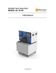
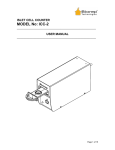
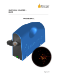
PERIFUSION SYSTEM
MODEL No: PERI-4.2
______________________________________________________
USER MANUAL
______________________________________________________
© BIOREP 2013 (2)
1
TABLE OF CONTENTS
GETTING STARTED.......................................................................................................................... 3
1
1.1
1.2
1.3
1.4
1.5
1.6
SYMBOLS USED IN THIS MANUAL ................................................................................................... 3
MACHINE INFORMATION ................................................................................................................. 3
CONTACT INFORMATION ................................................................................................................. 3
SAFETY INFORMATION .................................................................................................................... 4
SITE PREPARATION .......................................................................................................................... 5
PACKING LIST ................................................................................................................................. 5
2
INTRODUCTION ................................................................................................................................ 6
3
MACHINE PARTS IDENTIFICATION ........................................................................................... 7
4
ACCESSORIES .................................................................................................................................... 9
4.1
4.2
4.3
4.4
4.5
4.6
5
TUBING SET..................................................................................................................................... 9
PERIFUSION CHAMBER .................................................................................................................... 9
PERIFUSION CHAMBER AUXILIARY RACK........................................................................................10
COLLECTION WELL-PLATES ............................................................................................................10
BIO-GEL P-4 ...................................................................................................................................10
FIBERGLASS PRE-FILTERS ...............................................................................................................10
PERIFUSION SYSTEM OVERVIEW ..............................................................................................11
5.1
5.2
5.3
5.4
5.5
6
BASIC PERIFUSION SCHEMATIC ......................................................................................................11
VALVE MANIFOLD .........................................................................................................................12
PERISTALTIC PUMP .........................................................................................................................13
PERIFUSION CHAMBER....................................................................................................................13
COLLECTION TRAY .........................................................................................................................14
PERIFUSION SYSTEM BASICS ......................................................................................................15
6.1
6.2
6.3
6.4
6.5
7
POWER-UP .....................................................................................................................................15
LOGGING IN....................................................................................................................................16
MAIN MENU ...................................................................................................................................17
TEST PAGE .....................................................................................................................................18
SETTINGS........................................................................................................................................20
PERIFUSION OPERATION (PROTOCOL WIZARD) .................................................................21
7.1
7.2
7.3
7.4
7.5
7.6
7.7
7.8
7.9
7.10
8
CHAMBER POSITIONING ..................................................................................................................21
PROTOCOL ......................................................................................................................................21
SYSTEM SETUP ...............................................................................................................................22
CHAMBER SETUP ............................................................................................................................23
PERIFUSION TUBING SETUP ............................................................................................................24
PRIMING .........................................................................................................................................24
CELL LOADING ...............................................................................................................................25
CHAMBER POSITIONING ..................................................................................................................25
TEMPERATURE CONTROL................................................................................................................26
PROTOCOL EXECUTION ...................................................................................................................27
FINALIZING THE EXPERIMENT..................................................................................................29
8.1
8.2
9
10
COLLECTING THE CELLS .................................................................................................................29
CLEANING THE SYSTEM ..................................................................................................................29
REPORT ..............................................................................................................................................30
CUSTOMER SERVICE .................................................................................................................31
2
1
Getting Started
WARNING:
Please, read this section before unpacking, installing or
operating this machine.
1.1
Symbols Used in this Manual
The lightning flash with arrowhead symbol, within an equilateral triangle, is intended to
alert the user to the presence of dangerous voltage within the machine’s enclosure that
may be of sufficient magnitude to constitute a risk of electric shock.
The exclamation point within an equilateral triangle is intended to alert the user to the
presence of important information in the literature that accompanies the device.
This symbol warns of moving parts that may cause personal injury.
This symbol is used when two people are needed to do the task.
1.2
Machine Information
In the spaces provided below, record the Model and Serial No. located on the rear panel of your
machine.
Model No. __________________
Serial No.______________________
RETAIN THIS INFORMATION FOR FUTURE REFERENCE.
1.3
Contact Information
Biorep Technologies, Inc.
th
3225 NW 112 Street
Miami, FL 33167
[email protected]
www.biorep.com
Tel: 305-687-8074
Fax: 305-688-8029
3
1.4
Safety Information
WARNING:
DO NOT SKIP READING THIS SECTION.
PLEASE READ AND OBSERVE ALL WARNINGS AND INSTRUCTIONS GIVEN IN
THIS USER’S MANUAL AND THOSE MARKED ON THE UNIT.
RETAIN THIS BOOKLET FOR FUTURE REFERENCE.
DO NOT REMOVE THE MACHINE’S COVER OR YOU MAY BE EXPOSED TO
DANGEROUS VOLTAGE. REFER SERVICING TO QUALIFIED PERSONNEL ONLY.
TO REDUCE THE RISK OF FIRE OR ELECTRIC SHOCK, DO NOT EXPOSE THIS
DEVICE TO RAIN OR MOISTURE. DANGEROUS HIGH VOLTAGES ARE PRESENT
INSIDE THE ENCLOSURE.
READ AND UNDERSTAND HOW MOVING PARTS ARE CONTROLLED BEFORE
OPERATING THE MACHINE. KEEP YOUR FINGERS AWAY FROM MOVING
PARTS; NEGLECTING TO DO SO MAY CAUSE PERSONAL INJURY.
READ AND FOLLOW THESE INSTRUCTIONS:
1. Keep these instructions for future reference and heed all warnings stated in this manual.
2. Do not block any ventilation openings. Install the machine in accordance with the
manufacturer’s instructions. See Site Preparation in section 1.5 for details.
3. Do not defeat the safety purpose of the polarized or grounding-type plug. A polarized
plug has two blades with one wider than the other. A grounding-type plug has two blades
and a third grounding prong, which is provided for your safety. If the provided plug does
not fit into your outlet, consult an electrician for replacement of the obsolete outlet or
contact Biorep Technologies, Inc. at (305) 687-8074.
4. Protect the power cord, the power entry module, and the plug from being walked on or
pinched to avoid damaging them.
5. Refer all servicing of the machine to qualified personnel. Servicing is required when the
apparatus has been damaged in any way, for example: the power-supply cord or plug is
damaged, liquid has been spilled or objects have fallen into the apparatus, or if the
apparatus has been exposed to rain or moisture, has been dropped, or does not operate
normally for any reason.
4
1.5
Site Preparation
This machine is intended to work in a controlled laboratory environment. In order to properly
place the machine, please refer to the figure below. The machine has a ventilation opening in the
rear, which should not be blocked. A 12.7cm (5.0 in) clearance is recommended between the
back of the machine and any obstacle. Bench-space required is 49cm (19.3 in) x 65cm (25.6 in).
Figure 1: Site Preparation
1.6
Packing List
The following items are included with the purchase of a Perifusion system:
Qty
1
12
24
1
1
1
1
1
1
1
15
1
Reference
86610610
IS 3510
PERI-CHAMBER
PERI-TUB-12
60985-708
431412
150-4124
CO-A-3
12885T21
62408-940
PERI-NOZZLE
96410-16
Description
Power Cord
Pump cassettes
Perifusion Chambers
Two-Stop Tygon Tubing Set (pack of 12)
Silicone Tubing (50 ft)
Fiberglass Pre-filters (pack of 12)
Bio-Gel P-4 Gel (10 grams)
Perifusion Chamber Rack
Single Hole Punch
96 well-plate
Dispensing Nozzle
Size 16 Tubing for cooling tray
Pack of Clips
Replacement O-Rings
Table 1: Packing List
5
2
Introduction
Congratulations on your purchase of the Biorep Perifusion system. This is the newest generation
of a product that has received countless hours of development to include all the features
necessary to perform the most controlled and precise stimulated cell secretion experiments in the
field. You will not be disappointed with the value and efficiency this machine will bring to your
research.
The Perifusion system accurately stimulates and collects the secretions of pancreatic islets invitro. Its use has been extended to include the measurement of secretions of differentiated cells
derived from pancreatic progenitor stem cells. Coupled to a tandem mass spectrometer, the
Perifusion system can help identify molecules secreted during the stimulation of pancreatic islets.
The machine accurately controls temperature, flow, stimulus source and sample collection in up
to 8 channels in parallel. The Perifusion system is designed to execute pre-programmed
protocols that can last for hours and require several sample trays.
This User Manual is intended to be used by scientists, researchers, and technicians who have
received training in cell perifusion methods and technologies. This document contains the
necessary information for installing and operating the machine. However, it is not meant to
provide scientific guidance on perifusion protocols. Any perifusion protocols encountered in this
manual will be solely for the purpose of illustration of machine operation and should not be
interpreted otherwise.
3 Perfusion
4 Isolation
2 Organ Transportation
5 Purification
1 Donnor
8 Transplant
6 Perifusion
7 Cell Transport
Figure 2 Perifusion System in the islet isolation process
6
3
Machine parts identification
Figure 3: Perifusion system, side view
Figure 4: Perifusion system, front view
7
Figure 5: Perifusion system, back view
1. Removable source holder
2. 32 (8 x 4) valve manifold for source handling
3. 12 Channel peristaltic pump (Main pump)
4. Temperature control inlet/outlets (x6)
5. Perifusion chamber
6. Sample collection tray
7. Alarm buzzer
8. Tray cooling diaphragm pump
9. Power cable
10. Incubator cover
11. 12” Touch-Screen
12. E-Stop
13. Orbitor Enable (Optional Add-On)
14. Nameplate
15. USB 2.0 Port 1
16. USB 2.0 Port 2
17. RJ45 LAN Port
18. Power Entry Module
8
4
Accessories
A complete set of accessories is included with the machine. For ordering additional or
replacement accessories please consult our webpage www.biorep.com or contact one of our
sales representatives at (305) 687-8074.
4.1
Tubing Set
The Perifusion tubing set delivers the stimulus to the cell chamber while minimizing dead volume.
The perifusion tubing set is made out of 2 types of tubing: A- Connection tubing, which is for the
perifusion fluid handling system (source-manifold, manifold-pump, pump-chamber); and B- the
peristaltic pump tubing, which provides the precise resolution needed in perifusion experiments. A
set of each type is included with this machine.
Item
A
B
Description
Silicone Tubing; 0.040in ID, 0.085in OD
Two-Stop Tubing (Tygon R-3603) (orange-green);
0.015in ID, 0.035in WT;
Reference
89068-462
PERI-TUB-12
Table 2: Items Included in the Perifusion Tubing Set
4.2
Perifusion Chamber
The Perifusion chamber is where all cell reactions will take place. Substances will be delivered
through the inlet tube, cells contained in the chamber will react to the substances, and secretions
will come out the outlet tube for collection. A new system includes 16 perifusion chambers.
1- Inlet tube
2- Top cap
3- Top O-Ring
4- Cell chamber
5- Bottom O-Ring + Filter
6- Bottom cap
7- Outlet tube
Figure 6: Perifusion Chamber
9
4.3
Perifusion chamber auxiliary rack
The auxiliary rack is included with every Perifusion system
to assist in the preparation of the Perifusion chambers. The
rack can hold up to 8 chambers at a time for cell loading
outside the machine. This allows the scientist to do the
preparation away from the machine in a more comfortable
position.
Figure 7: Perifusion Chamber Rack
4.4
Collection well-plates
The collection well-plate is where the cell secretions and
the perfusate are collected for analysis. The Perifusion
system was designed to work with standard 96 well-plates,
and now has the ability to use high capacity, deep well
plates for longer experiments.
Figure 8: Collection Well-plate
4.5
Bio-Gel P-4
The Bio-Gel P-4 polyacrylamide beads are used at the time
of Perifusion chamber setup. They are used to sandwich
the cells inside the chamber to contain them and prevent
clogging of the filter.
To prepare the beads solution, use a 50ml conical test tube
and add 5ml of beads + 40ml of the buffer solution. Let the
solution sit overnight prior to a perifusion experiment.
Figure 9: Bio-Rad polyacrylamide beads
4.6
Fiberglass pre-filters
A fiberglass filter sheet is included with every perifusion
system. A hole puncher (included) is used to make round
cut-outs of the filter sheet to place inside the perifusion
chamber during its set-up. The purpose of this filter is to
retain the chamber contents while allowing the flow of the
perfusate.
Figure 10: Hole Punch
10
5
Perifusion system overview
5.1
Basic Perifusion schematic
The following schematic shows the basic functional elements and stages of the Perifusion
system. Potential users should become familiar with all the components of the system before
attempting to operate the machine.
Figure 11: Basic Perifusion Schematic
1. SOURCES: Up to eight different test solutions can be used as sources in a single experiment.
These sources can be administered either manually by the user or automatically by the machine
through the valve manifold. Sources are contained inside the enclosure’s temperature controlled
environment.
2. VALVE MANIFOLD: An automated valve manifold handles the source selection for each
channel. The manifold has 8 input channels (1, 2, 3…8) and four output channels A, B, C and D.
Each output channel is tripled, for a total of 12 output connections. A detailed description can be
found in section 5.2.
3. MAIN PUMP: A high precision, 12- channel peristaltic pump moves the test compounds from
the source, through the manifold, to the Perifusion chambers and out to the well plate.
4. PERIFUSION CHAMBER: The Perifusion chambers hold the cells to be stimulated. The input
to each chamber is the source selected by the manifold for its respective channel. The output will
contain the secretions and metabolites to be collected on the well plate. Up to eight Perifusion
chambers can be used in parallel.
5. TEMPERATURE CONTROL: All the test sources are housed in the same incubator enclosure
as the Perifusion chambers to provide a controlled temperature environment for the entire
process. A multi-point circulation design ensures temperature uniformity within 1ºC around the
Perifusion chambers.
6. COLLECTION: The perfusate is collected in a well plate for further analysis. The collection tray
moves automatically accordingly to the number of active columns (Perifusion chambers) and the
11
pre-set sampling rate. The collection tray can hold deep and standard 96 well plates; be sure to
place the included spacer adapter inside the tray to use it with standard plates.
7. REFRIGERATION: The collection tray can be refrigerated to avoid degradation of the analytes
in the perfusate during experiments. This is done by a dedicated diaphragm pump.
5.2
Valve Manifold
The valve manifold was designed to automate the selection of the stimulus. Manual source
changing is not only time consuming for the user, but it also increases the potential for artifacts on
the results. Manual source changing requires the user to pause the machine to avoid drawing air
into the system, but cell metabolism cannot be paused! Cells will continue to metabolize and,
when flow is resumed, a “spike” of metabolites will be generated at the output.
Minimizing this problem was a priority at the time of developing the new Perifusion system. The
result was a self contained, 32 valves, 8-in to 4-out manifold. The manifold can change the
source for every channel “on-the-fly” (milliseconds), eliminating the need for pausing the system.
It also eliminates the need for external sources requiring a separate heater; the sources can be
housed inside the machine, allowing for a better temperature control.
In conjunction with the ability to perform automated protocols, the valve manifold provides a
hands-off solution from start to finish of a Perifusion experiment. The user can now leave the
machine unattended and have the certainty that source changes will be made flawlessly every
time.
Figure 12: Valve Manifold
Understanding the valve manifold is key for a proper experiment setup. Inputs are located at the
bottom of the manifold block, starting with input 1 at the left (see fig. 12). Sources should be
connected to the input ports according with this numeration. There are four triplicate output
channels (A, B, C, D) located in the front of the manifold. Each triplet represents an output
channel, starting with channel A at the top.
Manifold states are represented by the letter and number combination “CHANNEL-SOURCE” for
each of the four channels: An, Bn, Cn, Dn, where n = 0-8, depending on the selected source (“0”
represents a closed channel).
12
Example: The manifold state: A2, B3, C8, D0, means that the three outputs of channel A will
output source 2, the three outputs of channel B will output source 3, the three outputs of channel
C will output source 8 and the three outputs of channel D are Inactive/closed.
Automated protocols will have a manifold state defined for each step. A detailed description of
protocol creation can be found in section 7.2.
5.3
Peristaltic pump
The sources are pumped from their containers through the open valves of the manifold by the
main pump. The main pump is a 12 roller, high precision peristaltic pump, capable of handling up
to 12 channels simultaneously, providing accurate and identical dispensing across channels.
Figure 13: Peristaltic Pump (Only 8 channels shown)
The main body of the pump (1), is fixed to the machine chassis. The special tubing (3) setup is
facilitated by individual cartridges (2). Cartridges snap in and out of the pump by pressing on the
release lever (4). A detailed description of tubing setup can be found in section 7.5.
5.4
Perifusion chamber
Sources delivered by the pump will react with the cells inside the perifusion chamber. The cells
are contained inside the chamber within a gel bead matrix. A fiberglass filter is used as a bottom
layer before the output. Secretions will come out the outlet tube for collection in the well-plate.
The internal volume is 275 µL. The chamber is translucent to allow visualization of its contents.
It is designed to fit a micro-centrifuge tube for easy cell recovery. This is important at the time of
data normalization. A detailed description of the chamber setup for an experiment can be found in
section 7.4.
13
1. Top cap
2. O-ring
3. Cell chamber
4. Fiberglass filter
5. Bottom cap
6. Micro-centrifuge tube
Figure 14: Perifusion Chamber and collection tube
5.5
Collection tray
Figure 15: Collection Tray
The collection tray (1) holds and positions the well-plate (2) for automated collection of the
perfusate and cell secretions according to programmed time intervals. The collection tray can be
used in a Horizontal or Vertical configuration with respect to the positioning mechanism (3). In
addition, the collection plate can be refrigerated by circulating fluid through the available ports (4).
The Perifusion system features a new deep collection tray that allows the use of large capacity 96
well plates. To use standard capacity well plates, insert the included spacer adapter into the tray.
When inserting the well-plate on the collection tray, make sure that well A1 is in
the position shown on Figure 15. This will ensure that the dispensing sequence
will start at this point, avoiding any confusion at the time of analysis.
14
6
Perifusion System Basics
Control and operation of the Perifusion system is done through the touch-screen interface. This
type of interface eliminates the need for an external keyboard or mouse device and provides a
visual and intuitive interaction with the user. The operator should familiarize himself/herself with
the different screens, features, and controls of the interface before attempting to operate the
machine during an actual perifusion.
Anyone who will operate and/or supervise the use of this machine should
read and understand this section in its entirety.
This machine has been designed with alarm features that will help the user
identify and correct potential problems. Alarm messages will be displayed at
the bottom of the screen. A detailed description of the different alarms can be
found later in this manual.
6.1
Power-Up
The machine’s main power switch and fuse-box are located on the back of the machine, above
the power entry module. Connect the power cord (provided in the accessory box) to the module
and then plug it into a 115/230 VAC outlet depending on your location. The red box in the module
displays the voltage rating intended for your machine.
Figure 16: Power Module
This screen will appear after a successful system
boot-up. Touch anywhere on the screen to
continue.
Figure 17: Power-up screen
15
6.2
Logging In
The Login Page allows you to Log into
your password protected user account.
The user account saves your protocols,
reports, and the preferences of your
experiments; it also saves time by prefilling some frequently used fields
during the experiment process and
during reporting.
The first step is creating a user
account. To create a new user account,
press the Add User Button.
When the “Add User” button is pressed,
the “New User Account” fields on the
right of the screen will be enabled.
Upon clicking on any field a pop-up
keyboard will appear. Enter a unique
username and password using the
keyboard and press “Accept”. Click
Save to create the user.
Now you will be able to find
name on the drop down list
left. The next time you do a
experiment, just select your
the list, enter your password
“Login”.
your User
at the top
Perifusion
user from
and press
Figure 18: Login page
16
6.3
Main Menu
Figure 19: Main Menu
Once logged in, you will arrive at the Main Menu page. On this page you can start an experiment,
via the “Protocol Wizard”; configure the settings of the machine, or manually control the different
sub-systems of the machine via the “Test Page”.
In this page you will also see the User account, the Software Version installed in your perfusion
machine, and the machine Status Bar at the bottom. The Status Bar will display any alarms or
important messages related to the function of the machine.
You can also end the session from this page either by logging out of your user account or by
turning the system off.
Please do not turn the machine off from the power entry module before being
prompted to do so.
17
6.4
Test Page
Figure 20: Test Page
The best way to get acquainted with the different sub-systems of the Perifusion machine is by
playing around in the Test Page. You can test the alarm buzzer by pressing the “Test Buzzer”
button, or confirm the proper sensing of the tray orientation by looking at the icon on the top right.
This icon should change when the tray is moved between “Landscape” and “Portrait” orientations.
MOTION: The motion controls manipulate the
position of the tray by enabling direct access to
the motors. Simply touch any direction arrow to
move the tray in the desired direction. You can
control the speed of the movement by changing
the “Velocity (Jog)” value. An X,Y position
indicator is provided in case you need to record
the position value for reference. Press HOME to
return to the starting position.
Figure 21: Motion Controls
18
TEMPERATURE:
The
temperature
systems can be tested by these controls.
The “HEATER” button enables the heater
and the convection fans. The incubator
PV (Present Value) will be displayed
below. The tray cooling pump can be
turned on by pressing the “Tray Pump”
button. The tray temperature will be
displayed below
Figure 22: Heater controls
FLUIDICS: The fluid handling manifold is
the most valuable sub-system for
automating a Perifusion experiment. It is
composed by the precision peristaltic
pump, and the 8 to 4 manifold. The pump
can be tested by assigning a value to the
“Pump Flow-rate” box. The state of each
of the 32 individual valves on the
perifusion can be manually changed by
touching the corresponding LED indicator
on the graphical array. An open valve is
represented by an ON indicator. It is not
recommended that you open all valves at
once.
Figure 23: Valve controls
At any point, press the BIOREP logo to return to the MAIN
MENU
Figure 2418: Return to Main Menu
19
6.5
Settings
Figure 25: Settings page
Before starting your perifusion experiments you have the option of customizing parameters
relating to the temperature alarms, tray handling and protocol execution timing.
ALARMS: The alarms are listed in the left hand side of the page. They can be de-activated in
case of a special case need, where a particular alarm is bothersome, but it is recommended that
all alarms remain active for protection of the machine.
TRAY HANDLING: Use this control to define which type of tray you are using in your experiments
(Deep or Standard). The “Orbitor Power” switch relates to the Orbitor robot accessory (Sold
separately). This option will be grayed out if your machine is not equipped with the Orbitor.
Please refer to the Orbitor manual for further instructions on operating Orbitor enabled machines.
TIMING: The timing controls are used for special protocol execution sequences.
ACTION REQUIRED ALARM: If the user does not want or can’t use the automatic manifold, the
“ACTION REQUIRED ALARM” should be activated. This causes the machine to alert the user
when any action is required to continue, such as manually changing the solution or changing the
tray. The user can define how much time ahead of a required action will the machine sound the
alarm. This will give the operator a chance to prepare for the change and minimize idle time. The
machine will automatically PAUSE execution when action is required. After the action is complete
the user must un-pause the machine manually to resume operation.
SKIP FIRST ROW: When this option is enabled, the machine will automatically start in row 2 of
every tray used in a protocol. This option is used when the first row of the tray will be post-filled
with a control sample by the user.
20
7
Perifusion Operation (Protocol Wizard)
Continuing our effort to make Perifusion experiments more streamlined, and reduce the chance of
error during setup, we have developed a “Wizard” type interface to set-up and run your
experiments. The wizard will guide you step by step through the setup of the machine, setup of
the sample, execution of your protocol, reporting of the results, and even post-experiment
maintenance of the machine.
Enter the wizard from the Main Menu screen by pressing the Protocol Wizard button (see 6.3).
7.1
Chamber positioning
On the first screen of the wizard you
will tell the machine how many
chambers you plan to use on your
experiment. You can use any number
from 1 to 12. Select the chambers to
be used by changing the value on the
top field. The Green indicators under
the chamber icons will light up,
confirming your choice, and reminding
you the positions of the chambers in
the chamber rack inside the incubator.
As a general rule, chambers should be
placed on the rack, starting from the
right-most position and adding more
chambers to the left. Chamber number
one (1) will always be the left-most
chamber.
Figure 26: Chamber positioning page
Misplacing the chambers will cause the collection sequence to fail. Please make sure
the chambers are numbered and located on the rack as shown by the wizard.
7.2
Protocol
On this screen you will be able to select or
create a protocol for the machine to run
automatically. A list of previously created
protocols will be shown as a list on the left
pane. The right pane shows the contents of
the protocol. A protocol is divided into a series
of steps, which are identified by the rows of
the table.
Each Step has the following attributes: Rep#
is the times the step is consecutively repeated
before changing to the next step. Time (sec)
determines the duration of each repetition
(Rep) of the step.
Figure 27: Protocol page
21
This means that a step with Rep# = 5 and Time = 20secs will dispense the selected solutions for
20 seconds, then move the collection tray to the next row of wells and dispense the same
solutions for another 20 seconds, and so on for 5 consecutive well rows. So in general, the total
dispensing time in a step would be the product of Rep# and Time, and distributed evenly in
consecutive well rows equal to Rep#.
The next column in the protocol is the Flow-rate (µL/min) in micro-liters per minute. This
determines the rate at which the solutions are supplied to the cells during the step. This
parameter controls the speed of the peristaltic pump. All channels will have the same flow.
The next four columns (A, B, C, D) relate to the automatic fluid handling system (see section 5.2).
In these fields you can assign the solution (1 to 8) for each of the channels. If you are not using
one of the channels, assign a zero "0" to the solution field.
The next and last column is the Pause option. This parameter will determine if the machine
pauses after a step is finished. This is an advanced option, where you need to perform a manual
operation between the steps. For all conventional Perifusion experiments, this option should be
set to NO.
On the top right of the screen you will find a # of Plates. This number will tell you the number of
well plates required to complete the protocol. This will help you have all the plates in hand to
avoid unnecessary delays.
Creating a Protocol
To create a protocol, click on the "NEW" button. Click "ADD STEP" button to add a step to your
protocol. A row filled with "X" will appear. Replace all the X with your protocol values. No X can
be left on the protocol. Repeat the process to add more steps. Assign a name to the protocol and
click "SAVE" to store your protocol in the machine's memory for future use. You will now see the
name of the new protocol displayed on the left pane.
Loading a Protocol
Biorep can provide you with a spreadsheet template that will allow you to create protocols from
the comfort of your office. Simply fill out the template as you would on the Perifusion touch-screen
and save the protocol onto a USB stick as a tab delimited text file. On the perifusion system, plug
the USB stick to one of the ports in the back of the machine; Click the "LOAD" button on the
wizard and navigate to the txt file you created. The protocol will be loaded into the wizard
interface and will be ready to save and execute.
7.3
System setup
Before an experiment can be performed, the machine has to be properly set-up and prepared.
The basic steps to complete are the following:
•
•
•
•
•
Chamber setup
Tubing setup
Source priming
Perifusion chamber cell loading
Pre-heating the incubator/ Cooling the sample tray
22
Some of these steps may be overlapping. Please read the entire setup instructions carefully
before attempting to do it on your machine. For further assistance please contact customer
support.
7.4
Chamber Setup
Prepare the perifusion chambers as shown in the wizard screen:
1. Use the included hole-puncher to cut the
necessary number of filters from the
fiberglass pre-filters. (You will need 2 filters
per chamber, so multiply the number of
chambers from step one of the wizard by
two to determine this number)
2. Place a circular fiberglass filter (2) inside the
bottom cap (1) bore.
3. Place an o-ring (3) on top of the filter.
Ensure no wrinkles are present on the filter.
4. Tighten the bottom lid (1) on the chamber
body (4)
5. Place the top o-ring (5) inside the chamber
body bore (4).
6. Connect the short section of the perfusion
tubing set (8) to the outlet tube of the bottom
cap. Push it all the way to the plastic. This
segment should be identical for all chambers
7. Connect the stainless steel nozzle (9) to the
bottom of the short tubing segment and
place the finished bottom section on the
auxiliary rack
8. To set up the top section, connect one end
of the three-stop tubing (orange-greenorange) (7) segment to the inlet tube of the
top cap
9. Repeat for all chambers being used. You
should end up with two halves as shown in
Figure 2 (of the screen)
Figure 19: Perifusion Chamber Assembly
Once you have both halves of the chamber pre-set, you can proceed to the tubing setup and to
the cell loading stage. The top half will be used in the tubing setup and the bottom half will be
loaded with cells. Once both stages are complete and the system is primed, the chamber can be
closed and will be ready to run an experiment.
23
7.5
Perifusion Tubing Setup
The tubing setup can be divided in two main parts: The source side and the chamber side. This
section will assume that the chamber has been set up as shown in section 7.4. Prepare the
tubing as described in the wizard screen
Source side- Number your input
source(s) (1) from 1 to 8 (max) and
connect them to the corresponding
port on the valve manifold (refer to
figure 12) with a 12in section of
0.04in ID tubing (2). Tubing lengths
are not critical on this side of the
manifold.
Chamber side- Connect a 3/4in
long segment (4) of 0.04in ID tubing
to the corresponding output of the
manifold and to the free end of the
three-stop tubing (5) (the other end
should be connected to the chamber
top cap(7). Insert the three-stop
tubing in the pump as follows:
1. The tubing (5) is inserted in the
cassette (6a) by sliding it
through the groove.
2. The orange colored detent (5a)
on the manifold side should
mate with the notch in the back
of the cassette.
Figure 2920: Tubing setup
3. The tubing should be longer on the chamber side than on the manifold side
4. When the tubing is secure, align the guide (6b) onto the pump bar and push the cassette
until the lever (6c) locks in place.
IMPORTANT: Ensure all lines have the same tubing section lengths on the chamber side (after
the manifold (sections: 4, 5, 7)). These sections make up the “dead volume” of the line. For best
results, it should be minimized and kept as even as possible between lines.
7.6
Priming
After the tubing is properly setup and the sources have
been connected, the system should be primed to remove
any air in the system. This was an involved process in
previous versions of the perifusion machine that is now
performed automatically by pressing PLAY button. The
machine automatically performs the priming sequence
depending on the active protocol. You will be able to
monitor the valve sequence followed by the machine as
it performs the priming. The progress will be displayed
on the bottom bar.
Figure 30: Priming page
24
7.7
Cell loading
When the system is completely primed and ready for the chamber to be attached:
1. Place the bottom half of the
assembled perifusion
chamber(s) (8) on the rack (7)
with the bottom cap (9) and filter
in place facing down.
2. Using a pipette, add 100µL of
the bead and buffer suspension
(5) to each chamber. Please
see Appendix A for bead
suspension preparation
instructions
3. When fluid starts dripping from
the nozzles (10), clamp the
tubing to retain the solution.
4. Add the cell sample (6)
5. Add another layer of the bead
suspension (5), making sure to
top-off the chamber
6. Start the pump slowly at
approximately 100µL/min until
solution starts dripping from the
top caps (4)
7. Screw each chamber to its
corresponding cap (4) by
carefully turning the chamber
body (8) and quickly remove the
clamp from the bottom outlet
8. Place each chamber (8) and
nozzle (10) in their designated
locations in the machine rack
9. Stop the pump. All valves will
close automatically
Figure 3121: Cell Loading
7.8
Chamber positioning
Care must be taken when positioning the perifusion chambers on the perifusion chamber rack
inside the incubator. Chamber placement starts from the right-most position with the last
chamber, and then subsequently filling positions to the left until the first chamber is placed. The
first chamber should be the leftmost chamber. This is of critical importance to the proper
functioning of the experiments; a misplaced chamber will deliver in the wrong well or even outside
the tray!
25
Please see the following examples:
Figure 32: Two active chambers
7.9
Figure 33: Four active chambers
Temperature control
Once the system has been prepared, the incubator must be heated up to the desired temperature
and the collection tray must be cooled down to preserve the analytes. Follow the on-screen
instructions.
Heating
1.
2.
3.
4.
Close the incubator cover
Press the "HEATER" button to enable the heater and turn on the fans
Allow approximately 20 minutes for the incubator "temp stable" LED to turn on
For better results and better temperature distribution, do not open the incubator cover
during the experiment. To re-fill the sources, run a tubing section from the source to the
outside of the incubator through the channels of the removable source tray.
IMPOTANT: If the incubator cover needs to be opened for any reason, turn the heater OFF. This
will ensure that when the incubator cover is closed, there is no temperature overshoot.
Cooling
1. To set up the tray cooling, fill a container with
coolant. The coolant can be chilled water or a
mixture of water and alcohol
2. Connect 1/8" I.D. silicone tubing as shown on the
figure
3. Prime the diaphragm pump using a siphon or
syringe
4. Press "TRAY PUMP" to turn the pump ON. Once
the tray pump is enabled, the button will turn blue
WARNING: Do not run pump dry!
Figure 3422: Cooling
26
7.10 Protocol execution
When you reach this screen the cells should be in the chambers, the manifold and should be
primed with the input solutions and the temperature of the incubator and tray should be at their
set points. On this screen you can start your Perifusion experiment by hitting the PLAY button.
The flow rate, manifold state, and movement of the tray will be automatically handled by the
machine. The machine will only require your input in special cases (as described in previous
sections), or when the machine requires manual change of the sample tray. This screen is
primarily used, as its name suggests, to monitor experiment progress.
Figure 3523: Protocol monitor
The Monitor screen can be divided in 5 functional sections:
EXECUTION CONTROLS
Figure 3624: Execution Controls
These controls allow you to START, PAUSE and STOP the
protocol execution at any time. Starting the execution of a
protocol requires two steps. The first time you press the
PLAY button, the machine will “HOME”. This will allow you
to load a 96 well plate into the sample tray. Press the PLAY
button once more to begin the protocol.
27
.
ALARMS AND INDICATORS
Figure 3725: Alarm Controls
This section of the protocol monitor displays the settings selected for the
protocol, like the type of 96 well plate (standard or deep); it also displays if
the SKIP FIRST ROW option was selected. When the Orbitor robot is
present, the indicator will display if it is enabled.
The speaker icon can be pressed to mute and un-mute the audible alarms.
TEMPERATURE
Figure 3826: Temperature controls.
These controls allow you to control and monitor the temperature settings of
the system. The HEATER button controls the incubator heater. The current
incubator temperature is displayed on the Incubator PV (Present Value)
indicator.
The TRAY PUMP button controls the cooling pump for the sample tray. The
tray temperature is displayed on the Tray PV indicator.
FLUIDICS
Figure 3927: Valve Controls
The changes in the fluid handling systems
can be monitored on-screen, by means of a
graphical valve map. The valve map will
display the open valves at any given time
during the protocol. The pump flow rate can
also be monitored.
TIMING
Figure 4028:Timing indicators.
These indicators will provide information related to the timing and
progression of the experiment. Since the experiment has many
chronological “levels”, these indicators will help you identify where you
are in your protocol. The first level locates you in the timing of the
repetition. Rep Time shows the elapsed time of the current repetition, and
Total Rep Time shows how long that repetition is.
The level below shows you where you are within the STEP. Rep #
identifies the current repetition out of the total repetitions of the current
step (Total Reps). The third level shows which step is currently being
executed (Step #) out of the total number of steps (Total Steps). Finally
the last level shows you which plate is currently being dispensed on. The
bar at the bottom shows you graphical progress of the entire experiment.
28
8
Finalizing the Experiment
8.1
Collecting the cells
1. Top cap
2. O-ring
3. Cell chamber
4. Fiberglass filter
5. Bottom cap
6. Micro-centrifuge tube
Figure 41 Perifusion Chamber and collection tube
To remove the beads and islets slur from the chamber, remove the bottom cap and introduce the
cell chamber into the micro-centrifuge tube. Remove the top cap and add 1 ml of Hank’s
balanced salt solution (HBSS) from the top so the slur goes down into the micro-centrifuge tube.
Centrifuge at 300g for 5 minutes and discard the supernatant. Lyse the cells with the beads.
Centrifuge again and assay the supernatant for DNA. There should be no beads in the
supernatant.
8.2
Cleaning the system
After the protocol has been executed successfully, the system must be thoroughly cleaned, not
only to ensure your system lasts longer, but most importantly, to eliminate all residues from the
fluidic system, that may cause the system to malfunction, or inadvertently affect the results of
future experiments.
The wizard includes a cleaning step to help you do this
in the most effective manner. Follow the on screen
instructions to perform a thorough cleaning.
The cleaning sequence has 4 steps:
1- Flush with de-ionized water. To do this, take all input
tubing to the manifold and change the source to draw up
from a de-ionized water container.
2- Sanitize with a mixture of 9 parts distilled water and 1
part bleach
3- Rinse once more with de-ionized water
4- Dry by drawing air (remove input tubing from the
manifold)
Figure 4229:Cleaning page
During the cleaning sequence the timing and valve sequence will be done automatically. The
wizard will pause between each of the four steps to give you time to change/remove the sources.
29
9
Report
After the cleaning sequence you
will be directed to the Report page.
Fill-in experiment specific
information required to generate the
automatic report:
1. Fill in the Experiment name.
2. Assign unique names to the
solutions used in the experiment.
The color key will be used in the
report to generate a map.
3. Assign the number of chambers
used for each of the output
channels.
4. Press GENERATE REPORT.
Figure 4330: Report page
Figure 4431:Sample report
An experiment report will be automatically generated. The report includes user and sample
information, and protocol specific information, such as the temperature profiles, the solutions
used, and the timing of the experiment. The most useful section of the report is the Well-Plate
maps, color coded according to the solution used. The plate maps are in tabular form,
representing the 96 well plate (8 x 12), and each cell represents an individual well. Each cell
contains two pieces of information. The color indicates which solution was used, and the number
indicates the STEP. This map is useful when cross-referencing the data to subsequent
processing such as ELISA.
30
10
Customer Service
If you encounter any problems, please contact customer support at:
Biorep Technologies, Inc.
3225 NW 112th Street
Miami, FL 33167
[email protected]
www.biorep.com
Tel: 305-687-8074
Fax: 305-688-8029
31
APPENDIX A
Buffer Preparation
Buffer Solvent: De-ionized water
Buffer Solute Ingredients/ Proportions:
32
Bead Suspension Preparation
•
•
•
•
•
Add beads to 5ml mark of a 50ml conical
Add 40ml of buffer solution.
Prepare bead-buffer suspension at least one day before the
experiment to allow beads to absorb buffer.
Keep the bead-buffer suspension refrigerated (4℃)
Bead suspension may be kept refrigerated for up to 4 weeks
Bead Suspension Use
Follow these instructions before using the bead suspension in a perifusion chamber preparation:
•
•
Warm bead suspension to 37℃ using an incubator or water bath. Do not add cold
bead suspension to cells, since this may adversely affect your experiment.
Agitate conical thoroughly before pipetting bead suspension to add into perifusion
columns. This ensures that approximately even number of beads are present in each
column.
33