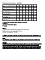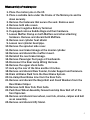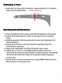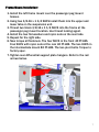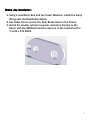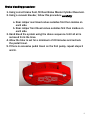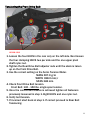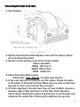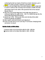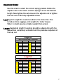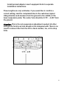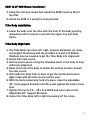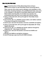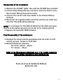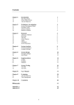
1
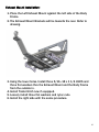
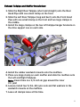
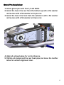
by
Trike Conversion Kit
2004 - Current
Harley-Davidson
Sportster
Installation Instructions
REVISED 1 - 2015
California Sidecar Parts & Technical Support
434.263.8866
Table of contents:
1.
2.
3.
4.
5.
6.
7.
8.
9.
10.
11.
12.
13.
14.
15.
16.
17.
18.
19.
20.
21.
22.
23.
Warnings and Considerations
Recommended Lubricants and Sealants
Maintenance Schedule
Disassembly of Motorcycle
Modification of Frame
Rear Suspension Unit Installation
Frame Mount Installation
Brake line Installation
Bleeding the Brake System
Exhaust Mount Installation
Exhaust Tailpipe and Muffler Installation
Gravel Pan Installation
Link to CSC Belt Tensioning Video
Setting up the Sonic Tension Meter
Using the Sonic Tension Meter
Tensioning the Front Drive Belt
Tensioning the Rear Drive Belt
Suspension Setup
Trike Body Installation
Trike Body Alignment
Securing the Trike Body
Reassembly of the Motorcycle
Final Reassembly of the Motorcycle
3
3
4
5
6
6
7
8
9
10
11
12
13
13
13
14
15
17
19
19
20
21
21
2
Warnings and Considerations:
1. Disclaimer - These instructions assume a level of understanding of
motorcycle repair and maintenance beyond that of a “beginner”
and/or “novice” and California Sidecar cannot be liable for an
installer’s failure to understand or follow these instructions as
written. Likewise, California Sidecar cannot be responsible if any
of the steps are omitted or shortcuts are taken, or parts other than
those supplied by California Sidecar, are used in installing this
trike kit.
2. “WARNINGS” are all printed in bold type and capitalized. They
mean to use extreme care in a given step so as not to damage the
part, motorcycle, and/or yourself.
3. Always wear safety glasses when using hand and/or power tools.
4. When working in and around the fuel system, always work in a
well-ventilated area, free from sparks and open flames.
5. All directional references to the “right side” and the “left side” are
as you were seated on the motorcycle.
6. All directional references to “forward” mean to the front of the
motorcycle while ”back” means the rear of the motorcycle unless
otherwise stated.
7. Please consult the appropriate Service Manual for your motorcycle
if further detail is necessary.
Recommended Lubricants and Sealants:
1. Molybdenum Disulfide grease for splines (Mobil Grease Moly 52 or
equivalent)
2. Multipurpose grease for Zerk fittings.
3. Thread locking compound (Loctite 242 minimum).
4. High temperature Silicone sealant.
3
Maintenance Schedule: LEGEND
Frequency (miles) Daily
4k
8k
12k
16k
20k
24k
I
I
I
I
T
I
Brake Pads and Rotors [1]
Half Shaft Boots
I
L
I
L
I
L
I
L
I
L
I
L
Wheel Bearings [2]
I
I
I
I
I
I
Wheels and Tires
All Lighting
Tire Pressure [3]
Brake fluid
I
I
I
I
I
I
I
I
R
I
I
R
Item
Belts
I
I
I
I: Inspect: clean, lubricate, and/or replace as necessary.
R: Replace
L: Lubricate with Silicone Spray
T: Tension
NOTE:
[1] Minimum pad thickness is 0.04 inches (1.02mm)
[2] Wheel bearing torque 200 FT.-LBS.
[3] Rear tire pressure 28 PSI
At higher odometer readings, repeat at frequency intervals established here.
Note:
This Schedule is in addition to the Harley Davidson Maintenance Schedule
NOTICE:
The remote door opener installed on this unit has a very small electrical draw
on your motorcycle battery. If your trike will be unridden for more than 2
weeks you should remove the 15 amp fuse from the red fuse holder located
under your seat or right side cover. Another option is using a battery tender.
4
Disassembly of motorcycle:
1. Place the motorcycle on the lift.
2. Place a suitable Jack under the Frame of the Motorcycle and tie
down securely.
3. Remove the fasteners that secure the seat. Remove seat.
4. Remove both side covers.
5. Disconnect negative Battery Terminal.
6. If equipped remove Saddle Bags and their hardware.
7. Loosen Muffler Clamp on both Mufflers and other attaching
hardware. Remove and discard both Mufflers.
8. Remove rear cylinder heat shield.
9. Loosen rear cylinder head pipe.
10. Remove the sprocket side cover.
11. Remove rear brake linkage at the master cylinder.
12. Remove and discard the muffler mount.
13. Reinstall the rear brake linkage.
14. Remove Passenger Foot pegs or Floorboards.
15. Disconnect the Rear Lamp Wiring Harness.
16. Remove the upper shock bolts.
17. Jack up the rear of the bike another 2 inches.
18. Remove and discard Rear Fender, Fender Support and fasteners.
19. Drain all Brake Fluid from the Rear Brake System.
20. Un-clamp Rear Brake Line from the Rear Fork.
21. Remove and discard the Banjo Bolt and Crush Washers from the
Rear Brake Caliper.
22. Remove both Rear Fork Pivot bolts.
23. Push Rear Wheel Assembly forward and slip Rear Belt off of the
front Sprocket.
24. Remove and discard rear wheel, rear fork, shocks, caliper and belt
as an assembly.
25. Remove and discard Jiffy Stand.
5
Modification of frame:
1. Cut frame as shown by the red line. Approximately 1 1/2 behind
shock bolt threaded hole.
Shock bolt hole.
Rear Suspension Unit Installation:
1. Place Suspension Unit using a jack behind prepared motorcycle.
2. Install two frame spacers inside of the upper shock threaded
holes.
3. Slide Suspension Unit forward past the pivot bolt alignment for
belt installation.
4. Install the front drive belt onto the Drive sprocket then the
transmission sprocket.
5. Align and install Rear Fork Pivot bolts but leave loose.
6. Install two 1/2-13 x 3 1/4 HHCS and flat washer thru the
intermediate mount bosses though the frame spacers and thread
into the frame from the inside out using thread locking agent.
Leave loose.
7. Reinstall the chrome front belt cover using OEM hardware and a
thick washer on the lower bolt.
6
Frame Mount Installation:
1. Install the left frame mount over the passenger peg mount
bosses.
2. Using two 3/8-16 x 1 3/4 SHCS install them into the upper and
lower tabs on the suspension unit.
3. Thread two black 3/8-16 x 1 1/4 SHCS into the frame at the
passenger peg mount location. Use thread locking agent.
4. Install the two flat washers and nyloc nuts on the rear tabs.
5. Repeat for the right side.
6. Now torque all fasteners. The four SHCS in the front 40 FT-LBS.
Four SHCS with nyloc nuts at the rear 40 FT-LBS. The two HHCS in
the intermediate mount 80 FT-LBS. The two pivot bolts. Torque to
factory spec.
7. Tighten rear differential support plate hangers. Refer to the red
arrows below.
7
Brake Line Installation:
1. Using a new Banjo Bolt and two Crush Washers, install the banjo
fitting onto the Distribution Block.
2. Use Cable Ties to secure the Rear Brake Hose to the Frame.
3. Install the master cylinder reservoir relocation bracket to the
frame with the OEM bolt and the reservoir to the bracket with a
1/4-20 x 5/8 SHCS.
8
Brake bleeding procedure:
1. Using correct brake fluid, fill Rear Brake Master Cylinder Reservoir.
2. Using a vacuum bleeder, follow this procedure carefully.
a. Rear caliper rear bleed valves outsides first then insides on
each side.
b. Rear caliper front bleed valves outsides first then insides on
each side.
3. Hand bleed the system using the above sequence. Until all air is
removed from the lines.
4. Allow the bike to set for a minimum of 20 minutes and recheck
the pedal travel.
5. If there is excessive pedal travel on the first pump, repeat steps 3
and 4.
9
Exhaust Mount Installation:
1. Place the Left Exhaust Mount against the left side of the Body
Frame.
2. The Exhaust Mount Brackets will be towards the rear. Refer to
drawing.
3. Using the lower holes. Install three 5/16–18 x 1 1/4 HHCS and
three flat washers thru the Exhaust Mount and the Body Frame
from the outside in.
4. Install Trailer Hitch now if equipped.
5. Loosely install three flat washers and nyloc nuts.
6. Install the right side with the same procedure.
10
Exhaust Tailpipe and Muffler Installation:
1. Slide the Right Rear Tailpipe (short and straight) onto the Rear
Head Pipe with one small clamp on the front.
2. Slide the Left Rear Tailpipe (long and bent) onto the Front Head
Pipe with one small clamp on the front and two large clamps in
the middle.
3. Install the large clamps on the two left tailpipe hanger brackets on
the drive support one on each side.
4. Install the rubber sandwich mounts onto the mufflers.
5. Place one large clamp on each muffler and slide the mufflers onto
the Left and Right Tailpipes.
Note: Insure there is a 1/2 inch air gap around the inner
C.V. joint
6. Loosely install four 5/16–18 nyloc nuts and flat washers to the
sandwich mounts on the mufflers.
7. Leave all clamps loose at this time.
11
Gravel Pan Installation:
1. Install gravel pan with four 1/4-20 HHCS.
2. Install the two in the rear from the bottom up with a flat washer
and secure with a flat washer and nyloc nut.
3. Install the two in the front from the outside in with a flat washer
and secure with a flat washer and nyloc nut.
4. Align all exhaust pipes for no interference.
5. Tighten all clamps and the rear head pipe, but leave the muffler
loose for vertical alignment later.
12
Link to CSC Belt Tensioning Video:
http://www.californiasidecar.com/support.html
Setting up the Sonic Tension Meter:
1. Turn power on, Push Select then 1.
2. Using the charts below in Front and Rear belt tensioning push Mass
then the numbers, Width and so on.
3. For the Rear belt push Select then 2. Reverse belt can be number 3
and so on.
Using the Sonic Tension Meter:
1. The microphone placement over the belt is critical.
a. The microphone should be in the middle of the belt width-wise.
b. The microphone should be equally in-between the two
Sprockets.
c. The microphone should be between ¼ and ½ an inch above or
below the Belt.
2. Turn the Sonic Tension Meter on.
3. Ensure that the correct setting is displayed on the LCD screen.
4. Push MEASURE then gently tap the Belt with a wrench while
holding the microphone in the correct position. A measurement in
Lbs. of single span tension should display. If not continue tightening
the Belt until a reading is displayed.
5. In noisy environments the Sonic Tension Meter may display errant
numbers. If so use in a quieter area.
6. Always take at least THREE readings of the Belt tension and
average the THREE readings to determine the actual tension of the
Belt.
13
Tensioning the Front Drive Belt:
TWO MORE ON
OTHER SIDE
1. Loosen the four HHCS in the rear only on the left side. Next loosen
the four clamping HHCS two per side and the one upper pivot
shaft nyloc nut.
2. Tighten the Rear Drive Belt adjuster nuts until the slack is taken
up on the Front Drive Belt.
3. Use the correct setting on the Sonic Tension Meter.
MASS 007.9 g/m
WIDTH 028.0 mm/r
SPAN 348 mm
4. Check Front Drive Belt tension.
Front Belt: 130 - 150 lbs. single span tension.
5. Once the correct belt tension is achieved tighten all fasteners
previously loosened in step 1. Eight HHCS and one nyloc nut.
6. Verify belt tension.
7. If incorrect start back at step 1. If correct proceed to Rear Belt
Tensioning.
14
Tensioning the Rear Drive Belt:
1. See diagram.
2. Tighten the Rear Drive Belt Adjuster nuts until the slack is taken
up on the Rear Drive Belt.
3. Use the correct setting on the Sonic Tension Meter.
50mm wide Belt:
MASS 007.9 g/m
WIDTH 050.0 mm/r
SPAN 0442 mm
4. Check Rear Drive Belt tension.
50mm belt: 130 - 150 lbs. of single span tension.
5. In the next step you are going to run the engine. Please be aware
of the safety of all those involved. Make sure you have at least two
lug nuts on each rotor and that they are tight.
6. To finish alignment, the belt must have at least 0.040in clearance
between edge of belt and fence on front Rear Drive Sprocket.
Check this by starting the engine and placing it in second gear and
simply let the engine idle. Checking the alignment by eye and
15
centering the belt as it spins. If belt has correct clearance, go to
step 8. If it does not have clearance, proceed to step 7.
7. Use the Left and Right Rear Drive Belt Adjuster Nuts to align belt
in order to achieve the necessary belt clearance. NOTE: The belt
will always track to the side of the sprocket that is the loosest.
Repeat step 4.
8. Once the correct belt alignment and single span tension is
achieved, tighten the eight 5/16 – 18 x 1 ¼ SHCS that go into the
Carrier Bearing Support Housings.
9. Install two 7/16 – 14 hex jam nuts onto the Rear Drive Belt
Tensioning Studs and tighten.
10. Once again verify belt tension and alignment.
11. If all is correct move on to next step. If not loosen clamping bolts
and return to step 4.
Service Limits on Drive Belts:
1. Service limit on the Front Drive Belt is 130 - 150 lbs.
2. Service limit on the Rear Drive Belt is 130 - 150 lbs.
16
Suspension Setup:
Use this chart to select the correct spring preload. Rotate the
adjuster nut on the shock until the spring is set to the desired
length. Now tighten the set screw on the adjuster nut or tighten
the lock nut on the fully adjustable shock.
Load: Typical weight the customer adds to the stock trike. This
includes riders, luggage, and weight of a trailer tongue.
When in doubt assume a higher weight than actual.
Length: Suggested length the spring should be adjusted to with the
suspension completely unloaded and the preloader adjusted all
the way out.
Legend
LOAD LENGTH
100
11 3/8
200
11
300
10 5/8
400
10 1/4
250 LB/IN SPRING
200 LB/IN SPRING
SHOCK with GREY SPRING
LOAD
100
200
300
400
500
LENGTH
11 1/2
11 3/16
10 7/8
10 9/16
10 1/4
Legend
LOAD LENGTH
100
13 3/8
200
13
300
12 5/8
400
12 1/4
250 LB/IN SPRING
200 LB/IN SPRING
SHOCK with RED SPRING
LOAD
100
200
300
400
500
LENGTH
13 1/2
13 3/16
12 7/8
12 9/16
12 1/4
17
Install preload adjuster now if equipped. Refer to separate
installation instructions.
These lengths are only estimates. If you would like to confirm a
correct setting, load the completed trike to the customers typical
riding situation and measure from the ground to the middle of the
lower suspension plate. The center hole should be 5.75” – 6.25” from
the ground.
Attention: This is the only suspension adjustment needed. All other
settings are factory set and should not be tampered with. There is no
need to remove trike from the lift to check camber, toe, or the drop
links.
5.75 – 6.25
18
2007 & UP ECM Mount installation:
1. Using the mid seat mount bolt install the ECM mount so that it
lays flat.
2. Install the ECM to it using the nuts provided.
Trike Body installation:
1. Lower the body onto the trike with the front of the body pointing
downward until it comes to rest onto the upper tray and body
frame.
Trike Body alignment:
1. The Trike Body can move left, right, forward, backward, up, down,
and angled. Shimming with the provided 1/4 and 1/8 Rubber
Washers may be required to get the Trike Body into alignment.
2. Install both side covers.
3. Set the seat in place. Using the threaded insert in the body to help
with body alignment
4. Raise the front of the body to obtain the vertical location around
the side covers.
5. Then slide the body front to back to get the horizontal location.
Again align with the side covers and the seat.
6. With the body temporarily held into place, raise the adjustable
90° body support brackets until they seat against the body’s inner
liner.
7. Tighten the two 5/16 – 18 x 3/4 HHCS and nyloc nuts on the
Adjustable 90° Support Brackets.
8. Center the Trike Body left to right measuring off the rotors.
19
Securing the trike body:
Note: A small section of Trike Body Carpet has not been
glued at the location of the Trike Body Frame mounting tabs to
allow removal of the bolts used in shipping, and installation of the
Trike Body mounting hardware. The predrilled bolt holes may need
to be enlarged or relocated for Trike Body attachment to the Trike
Body Frame mounting tabs. If relocation is necessary, the
preexisting holes will need to be sealed with silicone sealant.
1. Using a 5/16 twist drill, drill up through the Trike Body Frame
mounting tabs.
2. Insert 5/16–18 x 1 1/4 HHCS, fender washer, and rubber washers
if necessary through the holes drilled.
3. Install nyloc nuts and flat washers onto the rear HHCS and tighten.
4. Using a 5/16 twist drill, drill up through the Adjustable 90° Body
Support Brackets.
5. Insert 5/16–18 x 1 1/4 HHCS and fender washers through the
adjustable 90° body support brackets.
6. Install nyloc nuts and flat washers onto the front HHCS and
tighten.
7. Re-align the Mufflers and tighten hardware.
8. Install Passenger peg mounts with OEM hardware.
20
Reassembly of the motorcycle:
1. Replace the 15 AMP “lights” fuse with the 20 AMP fuse provided.
2. Connect Body Wiring Harness connector under the Frame to the
Rear Fender Wiring Harness Connector.
3. Connect the red wire with Fuse Holder to the Positive Battery
terminal.
4. Reconnect the negative battery terminal and the new white wire
from the Trike Body Wiring Harness.
NOTE: It is necessary for the LED tail lights that the white wire goes
directly to the battery ground and not just to the chassis ground.
5. Replace the Seat with OEM hardware.
Final Reassembly of the motorcycle:
1. Reinstall the wheel and tire assemblies with ten m12 x 1.5 ET
conical lug nuts. Torque to 75 FT-LBS.
2. Recommended tire pressure
15” & 16” wheels – 28 psi
17” wheels – 25 psi
Refer to the Maintenance Schedule on p. 4 for details regarding
future service inspections and maintenance.
From all of us at California Sidecar.
Enjoy the ride.
21