1
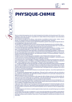
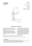
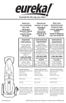
Process: MIG (GMAW) Flux cored (FCAW) Arc Welding Power Source and Wire Feeder Machine Number: ________________ Where Purchase: ________________ Date of purchased: ________________ MIGSONIC145 OWNER’S MANUAL www.weldking.com Table of Contents SECTION 1 SECTION 1 SAFETY PRECAUTIONS ................................................................................. 1 CONSIGNES DE SÉCURITÉ ............................................................................. 1 1-1. Symbol Usage ...................................................................................................... 1 Symboles utilisés .................................................................................................................. 1 1-2. Arc welding Hazards .......................................................................................... 1 Dangers relatifs au soudage à l’arc .................................................................................. 1 1-3. Safety Standards Normes de sécurité .................................................... 6 1-4. EMF Information EMF Information .......................................................... 6 SECTION 2 INSTALLATIONS................................................................................................ 7 2-1. Welding power source specifications ........................................................... 7 2-2. Connection diagram ........................................................................................... 8 2-3. installing welding torch ................................................................................... 10 2-4. Ground cable installation................................................................................ 11 2-5. Process/Polarity Table ..................................................................................... 11 2-6. Install procedure ............................................................................................... 11 2-7. Electric service guide ...................................................................................... 12 2-8. Extension Cable Selection Chart .................................................................. 13 SECTION 3 OPERATION .......................................................................................................... 14 3-1 Front panel Layout ........................................................................................... 14 3-2 Operation ............................................................................................................ 15 3-3 Voltage/Wire speed selection chart .............................................................. 16 SECTION 4 TROUBLE SHOOTING...................................................................................... 17 SECTION 5 MAINTENANCE....................................................................................................... 22 5.1. Maintenance ....................................................................................................... 22 5.2. Safety precaution .............................................................................................. 23 SECTION 6 SECTION 7 SECTION 8 PARTS LIST ...................................................................................................... 25 WARRANTY POLICY ...................................................................................... 32 AUTHORIZED SERVICE CENTER ............................................................... 33 SECTION 1 SECTION 1 1-1. SAFETY PRECAUTIONS CONSIGNES DE SÉCURITÉ Symbol Usage Symboles utilisés Means Warning! Watch Out! There are possible hazards with this procedure! The possible hazards are shown in the adjoining symbols. This group of symbols means Warning! Watch Out possible ELECTRIC SHOCK, MOVING PARTS, and HOT PARTS hazards. Consult symbols and related instructions below for necessary actions to avoid the hazards Symbole graphique d’avertissement ! Attention ! Cette procedure comporte des risques possibles ! Les dangers éventuels sont représentés par les symboles graphiques joints. Ce groupe de symboles signifie Avertissement! Attention! Risques d’ÉLECTROCUTION, ORGANES MOBILES et PARTIES CHAUDES. Consulter les symboles et les instructions afferents ci-dessous concernant les mesures à prendre pour supprimer les dangers. Marks a special safety message. Indique un message de sécurité particulier Means “Note”; not safety related. Signifie NOTE ; n’est pas relatif à la sécurité. 1-2. Arc welding Hazards Dangers relatifs au soudage à l’arc ELECTRIC SHOCK can kill. UNE DÉCHARGE ÉLECTRIQUE entraîner la mort. The symbols shown below are used throughout this manual to call attention to and identify possible hazards. When you see the symbol, watch out, and follow the related instructions to avoid the hazard. Only qualified persons should service, test, maintain, and re- pair this unit. y y During servicing, keep everybody, especially children, away y Les symboles représentés ci-dessous sont utilisés dans ce manuelpour attirer l’attention et identifier les dangers possibles. Enprésence de l’un de ces symboles, prendre garde et suivre lesinstructions afférentes pour éviter tout risque. Les instructions enmatière de sécurité indiquées ci-dessous ne constituent qu’un sommaire des instructions de sécurité plus complètes fournies dans les normes de sécurité énumérées dans la Section 2-5. Lire et observer toutes les normes de sécurité. Seul un personnel qualifié est autorisé à installer, faire fonctionner, entretenir et réparer cet appareil. Pendant le fonctionnement, maintenir à distance toutes les personnes, notamment les enfants de l’appareil. y y y y Do not touch live electrical parts. Wear dry, hole-free insulating gloves and body protection. Insulate yourself from work and ground using dry insulating mats or covers big enough to prevent any physical contact with the work or ground. Do not use AC output in damp areas, if movement is confined, or if there is a danger of falling. Use AC output ONLY if required for the welding process. If AC output is required, use remote output control if present on unit. Additional safety precautions are required when any of the following electrically hazardous conditions are present: in damp locations or while wearing wet clothing; on metal structures such as floors, gratings, or scaffolds; when in cramped positions such as sitting, kneeling, or lying; or when there is a high risk of unavoidable or accidental contact with the workpiece or ground. For these conditions, use the following equipment in order presented: 1) a semiautomatic DC constant voltage (wire) welder, 2) a DC manual (stick) welder, or 3) an AC welder with reduced open-circuit Page 1 y y y y y y y y y y y y y y y y y voltage. In most situations, use of a DC, constant voltage wire welder is recommended. And, do not work alone! Disconnect input power or stop engine before installing or servicing this equipment. Lockout/tagout input power according to OSHA 29 CFR 1910.147 (see Safety Standards). Properly install and ground this equipment according to its Owner’s Manual and national, state, and local codes. Always verify the supply ground − check and be sure that input power cord ground wire is properly connected to ground terminal in disconnect box or that cord plug is connected to a properly grounded receptacle outlet. When making input connections, attach proper grounding conductor first − double-check connections. Frequently inspect input power cord for damage or bare wiring − replace cord immediately if damaged − bare wiring can kill. Turn off all equipment when not in use. Do not use worn, damaged, undersized, or poorly spliced cables. Do not drape cables over your body. If earth grounding of the workpiece is required, ground it directly with a separate cable. Do not touch electrode if you are in contact with the work, ground, or another electrode from a different machine. Do not touch electrode holders connected to two welding machines at the same time since double open-circuit voltage will be present. Use only well-maintained equipment. Repair or replace damaged parts at once. Maintain unit according to manual. Wear a safety harness if working above floor level. Keep all panels and covers securely in place. Clamp work cable with good metal-to-metal contact to workpiece or worktable as near the weld as practical. Insulate work clamp when not connected to workpiece to prevent contact with any metal object. Do not connect more than one electrode or work cable to any single weld output terminal. SIGNIFICANT DC VOLTAGE exists after removal of input power on inverters. y y y y y y y y y y y y y y Turn Off inverter, disconnect input power, and discharge input capacitors according to instructions in Maintenance Section before touching any parts. y Ne pas toucher aux pièces électriques sous tension. Porter des gants isolants et des vêtements de protection secs et sans trous. S’isoler de la pièce à couper et du sol en y y y y utilisant des housses ou des tapis assez grands afin d’éviter tout contact physique avec la pièce à couper ou le sol. Ne pas se servir de source électrique à courant électrique dans les zones humides, dans les endroits confinés ou là où on risque de tomber. Se servir d’une source électrique à courant électrique UNIQUEMENT si le procédé de soudage le demande. Si l’utilisation d’une source électrique à courant électrique s’avère nécessaire, se servir de la fonction de télécommande si l’appareil en est équipé. D’autres consignes de sécurité sont nécessaires dans les conditions suivantes : risques électriques dans un environnement humide ou si l’on porte des vêtements mouillés ; sur des structures métalliques telles que sols, grilles ou échafaudages ; en position coincée comme assise, à genoux ou couchée ; ou s’il y a un risque élevé de contact inévitable ou accidentel avec la pièce à souder ou le sol. Dans ces conditions, utiliser les équipements suivants, dans l’ordre indiqué : 1) un poste à souder DC à tension constante (à fil), 2) un poste à souder DC manuel (électrode) ou 3) un poste à souder AC à tension à vide réduite. Dans la plupart des situations, l’utilisation d’un poste à souder DC à fil à tension constante est recommandée. En outre, ne pas travailler seul ! Couper l’alimentation ou arrêter le moteur avant de procéder à l’installation, à la réparation ou à l’entretien de l’appareil. Déverrouiller l’alimentation selon la norme OSHA 29 CFR 1910.147 (voir normes de sécurité). Installer le poste correctement et le mettre à la terre convenablement selon les consignes du manuel de l’opérateur et les normes nationales, provinciales et locales. Toujours vérifier la terre du cordon d’alimentation. Vérifier et s’assurer que le fil de terre du cordon d’alimentation est bien raccordé à la borne de terre du sectionneur ou que la fiche du cordon est raccordée à une prise correctement mise à la terre. En effectuant les raccordements d’entrée, fixer d’abord le conducteur de mise à la terre approprié et contre-vérifier les connexions. Vérifier fréquemment le cordon d’alimentation afin de s’assurer qu’il n’est pas altéré ou à nu, le remplacer immédiatement s’il l’est. Un fil à nu peut entraîner la mort. L’équipement doit être hors tension lorsqu’il n’est pas utilisé. Ne pas utiliser des câbles usés, endommagés, de grosseur insuffisante ou mal épissés. Ne pas enrouler les câbles autour du corps. Si la pièce soudée doit être mise à la terre, le faire directement avec un câble distinct. Ne pas toucher l’électrode quand on est en contact avec la pièce, la terre ou une électrode provenant d’une autre machine. Ne pas toucher des porte électrodes connectés à deux machines en même Page 2 temps à cause de la présence d’une tension à vide doublée. N’utiliser qu’un matériel en bon état. Réparer ou remplacer sur-lechamp les pièces endommagées. Entretenir l’appareil conformément à ce manuel. Porter un harnais de sécurité si l’on doit travailler au-dessus du sol. S’assurer que tous les panneaux et couvercles sont correctement en place. Fixer le câble de retour de façon à obtenir un bon contact métal-métal avec la pièce à souder ou la table de travail, le plus près possible de la soudure. Isoler la pince de masse quand pas mis à la pièce pour éviter le contact avec tout objet métallique. Ne pas raccorder plus d’une électrode ou plus d’un câble de masse à une même borne de sortie de soudage. y y y y y y y Ne pas surcharger l’installation électrique − s’assurer que l’alimentation est correctement dimensionnée et protégée avant de mettre l’appareil en service. FLYING METAL can injure eyes. DES PARTICULES VOLANTES peuvent blesser les yeux. y y y Il reste une TENSION DC NON NÉGLIGEABLE dans les sources de soudage onduleur quand on a coupe l’alimentation. y Arrêter les convertisseurs, débrancher le courant électrique et décharger les condensateurs d’alimentation selon les instructions indiquées dans la partie Entretien avant de toucher les pièces. y y y y y y y Ne pas toucher des parties chaudes à mains nues. y Prévoir une période de refroidissement avant d’utiliser le pistolet ou la torche. MAGNETIC FIELDS can affect pacemakers. LES CHAMPS MAGNÉTIQUES peuvent affecter les stimulateurs cardiaques. Établir la connexion avec la arrette de terre avant de manipuler des cartes ou des pièces. Utiliser des pochettes et des boîtes antistatiques pour stocker, déplacer ou expédier des cartes PC. Risque D’INCENDIE OU D’EXPLOSION. y y Do not touches hot parts bare handed. y Allow cooling period before working on welding gun or torch Put on grounded wrist strap BEFORE handling boards or parts. Use proper static-proof bags and boxes to store, move, or ship PC boards. FIRE OR EXPLOSION hazard. Do not place unit on, over, or near combustible surfaces. Do not service unit near flammables Do not overload building wiring − be sure power supply system is properly sized, rated, and protected to handle this unit. Le soudage, l’écaillement, le passage de la pièce à la brosse en fil de fer, et le meulage génèrent des étincelles et des particules métalliques volantes. Pendant la période de refroidissement des soudures, elles risquent de projeter du laitier. Porter des lunettes de sécurité avec écrans latéraux ou un écran facial. HOT PARTS can cause severe burns. DES PIÈCES CHAUDES peuvent provoquer des brûlures graves. STATIC (ESD) can damage PC boards. LES CHARGES ÉLECTROSTATIQUES peuvent endommager les circuits imprimés. y Wear safety glasses with side shields or face shield during servicing. Be careful not to short metal tools, parts, or wires together during testing and servicing. y y Pacemaker wearers keep away. Wearers should consult their doctor before going near arc welding, gouging, or spot welding operations. y Porteurs de stimulateur cardiaque, rester à distance. Les porteurs d’un stimulateur cardiaque doivent d’abord consulter leur médecin avant de s’approcher des opérations de soudage à l’arc, de gougeage ou de soudage par points. y Ne pas placer l’appareil sur, au-dessus ou à proximité de surfaces inflammables. y Ne pas installer l’appareil à proximité de produits inflammables. y Page 3 CYLINDERS can explode if damaged. LES BOUTEILLES peuvent exploser si elles sont endommagées. Shielding gas cylinders contain gas under high pressure. If damaged, a cylinder can explode. Since gas cylinders are normally part of the welding process, be sure to treat them carefully. y Protect compressed gas cylinders from excessive heat, mechanical shocks, physical damage, slag, open flames, sparks, and arcs. y Install cylinders in an upright position by securing to a stationary support or cylinder rack to prevent falling or tipping. y Keep cylinders away from any welding or other electrical circuits. y Never drape a welding torch over a gas cylinder. y Never allow a welding electrode to touch any cylinder. y Never weld on a pressurized cylinder − explosion will result. y Use only correct shielding gas cylinders, regulators, hoses, and fittings designed for the specific application; maintain them and associated parts in good condition. y Turn face away from valve outlet when opening cylinder valve. y Keep protective cap in place over valve except when cylinder is in use or connected for use. y Use the right equipment, correct procedures, and sufficient number of persons to lift and move cylinders. y Read and follow instructions on compressed gas cylinders, associated equipment, and Compressed Gas Association (CGA) publication P-1 listed in Safety Standards. Des bouteilles de gaz protecteur contiennent du gaz sous haute pression. Si une bouteille est endommagée, elle peut exploser. Du fait que les bouteilles de gaz font normalement artie du procédé de soudage, les manipuler avec précaution. y Protéger les bouteilles de gaz comprimé d’une chaleur excessive, des chocs mécaniques, des dommages physiques, du laitier, des flammes ouvertes, des étincelles et des arcs. y Placer les bouteilles debout en les fixant dans un support stationnaire ou dans un porte-bouteilles pour les empêcher de tomber ou de se renverser. y Tenir les bouteilles éloignées des circuits de soudage ou autres circuits électriques. y Ne jamais placer une torche de soudage sur une bouteille à gaz. y Une électrode de soudage ne doit jamais entrer en contact avec une bouteille. y Ne jamais souder une bouteille pressurisée − risque d’explosion. y Utiliser seulement des bouteilles de gaz protecteur, régulateurs, tuyaux et raccords convenables pour cette application spécifique ; les maintenir ainsi que les éléments associés en bon état. y Détourner votre visage du détendeur-régulateur lorsque vous ouvrez la soupape de la bouteille. y Le couvercle du détendeur doit toujours être en place, sauf lorsque la bouteille est utilisée ou qu’elle est reliée pour usage ultérieur. y Utiliser les équipements corrects, les bonnes procédures et suffisamment de personnes pour soulever et déplacer les bouteilles. y Lire et suivre les instructions sur les bouteilles de gaz comprimé, l’équipement connexe et le dépliant P-1 de la CGA (Compressed Gas Association) mentionné dans les principales normes de sécurité. FALLING UNIT cause injury. LA CHUTE L’APPAREIL blesser. y y y y y y can DE peut Use lifting eye to lift unit only, NOT running gear, gas cylinders, or any other accessories. Use equipment of adequate capacity to lift and support unit. If using lift forks to move unit, be sure forks are long enough to extend beyond opposite side of unit Utiliser l’anneau de levage uniquement pour soulever l’appareil, NON PAS les chariots, les bouteilles de gaz ou tout autre accessoire. Utiliser un équipement de levage de capacité suffisante pour lever l’appareil. En utilisant des fourches de levage pour déplacer l’unité, s’assurer que les fourches sont suffisamment longues pour dépasser du côté opposé de l’appareil. MOVING PARTS can cause injury. DES ORGANES MOBILES peuvent provoquer des blessures. y y y y y y y y Keep away from moving parts such as fans. Keep all doors, panels, covers, and guards closed and securely in place. Have only qualified persons remove doors, panels, covers, or guards for maintenance as necessary. Reinstall doors, panels, covers, or guards when maintenance is finished and before reconnecting input power. S’abstenir de toucher des organes mobiles tells que des ventilateurs. Maintenir fermés et verrouillés les portes, panneaux, recouvrements et dispositifs de protection. Seules des personnes qualifiées sont autorisées à enlever les portes, panneaux, recouvrements ou dispositifs de protection pour l’entretien. Remettre les portes, panneaux, recouvrements ou dispositifs de protection quand l’entretien est terminé et avant de rebrancher l’alimentation électrique. Page 4 MOVING PARTS can cause injury. DES ORGANES MOBILES peuvent provoquer des blessures. y y Keep away from moving parts Keep away from pinch points such as drive rolls y y Ne pas s’approcher des organes mobiles. Ne pas s’approcher des points de coincement tels que des rouleaux de commande. OVERUSE can cause OVERHEATING. L’EMPLOI EXCESSIF peut SURCHAUFFER L’ÉQUIPEMENT. Allow cooling period; follow rated duty cycle. Reduce current or reduce duty cycle before starting to weld again. Do not block or filter airflow to unit interference problem resulting from the installation. If notified by the FCC about interference, stop using the equipment at once. Have the installation regularly checked and maintained. Keep high-frequency source doors and panels tightly shut, keep spark gaps at correct setting, and use grounding and shielding to minimize the possibility of interference. y y y Le rayonnement haute fréquence (HF) peut provoquer des interférences avec les équipements de radio-navigation et de communication, les services de sécurité et les ordinateurs. Demander seulement à des personnes qualifiées familiarisées avec des équipements électroniques de faire fonctionner l’installation. L’utilisateur est tenu de faire corriger rapidement par un electrician qualifié les interférences résultant de l’installation. Si le FCC signale des interférences, arrêter immédiatement l’appareil. Effectuer régulièrement le contrôle et l’entretien de l’installation. y y y y y y Prévoir une période de refroidissement ; respecter le cycle opératoire nominal. Réduire le courant ou le facteur de marche avant de poursuivre le soudage. Ne pas obstruer les passages d’air du poste. H.F. RADIATION can cause interference. LE SOUDAGE À L’ARC risque de provoquer des interférences. y y y High-frequency (H.F.) can interfere with radio navigation, safety services, computers, and communications equipment. Have only qualified persons familiar with electronic equipment perform this installation. The user is responsible for having a qualified electrician promptly correct any Maintenir soigneusement fermés les portes et les panneaux des sources de haute fréquence, maintenir les éclateurs à une distance correcte et utiliser une terre et un blindage pour réduire les interférences éventuelles. READ INSTRUCTIONS. LIRE LES INSTRUCTIONS. Consult the Owner’s Manual for welding safety precautions. Use only genuine replacement parts Lire le manuel d’utilisation avant d’utiliser ou d’intervenir sur l’appareil. Utiliser uniquement des pièces de rechange. Page 5 1-3. Safety Standards Normes de sécurité Safety in Welding, Cutting, and Allied Processes, ANSI Standard Z49.1, from Global Engineering Documents (phone: 1-877-413-5184, website: www.global.ihs.com). Code for Safety in Welding and Cutting, CSA Standard W117.2, from Canadian Standards Association, Standards Sales, 178 Rexdale Boulevard, Rexdale, Ontario, Canada M9W 1R3 (phone: 800−463−6727 or in Toronto 416−747−4044, website: www.csa−international.org). Safety in Welding, Cutting, and Allied Processes, ANSI Standard Z49.1, de Global Engineering Documents (téléphone : 1-877-413-5184, site Internet : www.global.ihs.com). Code for Safety in Welding and Cutting, CSA Standard W117.2, de Canadian Standards Association, Standards Sales, 178 Rexdale Boulevard, Rexdale, Ontario, Canada M9W 1R3 (téléphone : 800-463-6727 ou à Toronto 416-747-4044, site Internet : www.csa-international.org). 1-4. EMF Information EMF Information Considerations About Welding And The Effects Of Low Frequency Electric And Magnetic Fields 1. Keep cables close together by twisting or taping them. Welding current, as it flows through welding cables, will cause electro- magnetic fields. There has been and still is some concern about such fields. However, after examining more than 500 studies spanning 17 years of research, a special blue ribbon committee of the National Research Council concluded that: “The body of evidence, in the committee’s judgment, has not demonstrated that exposure to power- frequency electric and magnetic fields is a human-health hazard.” However, studies are still going forth and evidence continues to be examined. Until the final conclusions of the research are reached, you may wish to minimize your exposure to electromagnetic fields when welding or cutting. 2. Arrange cables to one side and away from the operator. To reduce magnetic fields in the workplace, use the following procedures: Considérations sur le soudage et les effets de basse fréquence et des champs magnétiques et électriques. Le courant de soudage, pendant son passage dans les câbles de soudage, causera des champs électromagnétiques. Il y a eu et il y a encore un certain souci à propos de tels champs. Cependant, après avoir examine plus de 500 études qui ont été faites pendant une période de recherché de 17 ans, un comité spécial ruban bleu du National Research Council a conclu : « L’accumulation de preuves, suivant le jugement du comité, n’a pas démontré que l’exposition aux champs magnétiques et champs électriques à haute fréquence représente un risque à la santé humaine ». Toutefois, des études sont toujours en cours et les preuves continuent à être examinées. En attendant que les conclusions finales de la recherché soient établies, il vous serait souhaitable de réduire votre exposition aux champs électromagnétiques pendant le soudage ou le coupage. Pour réduire les champs magnétiques sur le poste de travail, appliquer les procédures suivantes : 3. Do not coil or drape cables around your body. 4. Keep welding power source and cables as far away from operator as practical. 5. Connect work clamp to work piece as close to the weld as possible. About Pacemakers: Pacemaker wearers consult your doctor first. If cleared by your doctor, then following the above procedures is recommended 1. Maintenir les câbles ensemble en les tordant ou en les enveloppant. 2. Disposer les câbles d’un côté et à distance de l’opérateur. 3. Ne pas courber pas et ne pas entourer pas les câbles autour de votre corps. 4. Garder le poste de soudage et les câbles le plus loin possible de vous. 5. Connecter la pince sur la pièce aussi près que possible de la soudure. En ce qui concer ne les sti mulateurs cardiaques Les porteurs de stimulateur cardiaque doivent consulter leur médecin avant de souder ou d’approcher des opérations de soudage. Si le médecin approuve, il est recommandé de suivre les procédures précédentes Page 6 SECTION 2 INSTALLATIONS 2-1. Welding power source specifications MIGSONIC145 Type Power supply 115V/60Hz 230V/60Hz 1 Phase Input current @ Maximum output 20 21 Rated input (Kva) 2.3 4.8 Open circuit voltage(v) 44 44 Amperage range(A) 40-110 40-180 Welding voltage(V) 16-18.5 16-21.3 Rated Duty cycle (%) 60 60 Rated welding current(A) 90 145 31-590 (0.8-15 m/min) Wire feed speed(IPM) 52 x25.5 x51 Dimension(HxWxD)(CM) 20 Weight(KG) Steel /Stainless Steel Wire Diameter(MM) Solid: 0.6-0.9mm (0.023-0.035in) Flux cored: 0.8-1.2mm (0.030-0.045in) -4°F to 104°F(-20 to +40°C) Operating temperature Storage temperature -40°F to 185°F (-40°C to +40°C) Table 2.1 CAUTION WELDING LONGER THAN RATED DUTY CYCLE CAN DAMAGE GUN AND VOID WARRANTY. Page 7 2-2. Connection diagram MIGSONIC145 (115v input) Gauge Cylinder Power Cord To 115 volt, 20 ampere individual branch circuit Torch Figure 2.1 Page 8 MigSonic145(208/230V input) Gauge Cylinder Power Cord Torch Figure 2.2 Page 9 2-3. installing welding torch Correct Incorrect Figure 2.3 1. 2. 3. Gun Securing Knob Gun End: Loose knob. Insert gun end through opening until it bottoms against drive assembly. Tighten knob. Gun Trigger connector: Insert into receptacle, and tighten. Close door. Page 10 2-4. Ground cable installation Figure 2.4 1. Ground cable 2. Output Terminal Block 3. Insert ground cable through opening in front panel and route along back of front panel to output terminal block. Close door. 2-5. Process/Polarity Table Cable Connections Process Polarity Cable To Gun Cable To Work GMAW-Solid wire with shielding gas DCEP – Reverse polarity Connect to positive(+) output terminal Connect to negative(-)output terminal FCAW – Self-shielding wire- no shielding gas DCEN-Straight Polarity Connect to negative(-) output terminal Connect to positive(+)output terminal Table 2.2 2-6. Install procedure 2-6.1. Welding machine should be installed in a stable position and with good ventilation. Avoid direct sun outdoors. Use forklift to move, avoid transport in invert or side position. 2-6.2. Be sure machine is well grounded. Connect the bolt marked “earth ” with earth in network, then connect to network firmly 2-6.3. Before starting a new machine or the machine idled for a period, check the insulation resistance of circuit which is connected to the network. The resistance must be higher than 2.5M Ω; otherwise the machine must be dried. 2-6.4. Connect torch, earth cable, wire, regulator, cylinder according to connection diagram. Note: Connection hardware must be tightened with proper tools. Do not just hands tighten hardware! A loose electrical connection will cause poor weld performance and excessive heating at the terminal Page 11 block. 2-6.5. Use Ф8 heat-resistant PVC hose connect the flow meter with the gas connection nipple at rear of the machine. 2-6.6. Install wire spool. 4 in (100mm) wire spool: Figure 2.5 8 in (200mm) wire spool: Figure 2.6 Commission the machine after the machine is installed and tested: Release the pressure roller in the wire feeder, push the torch switch, and adjust voltage switch from low to high, Open circuit voltage should rise. Evenly adjust the current knob, the wire feed speed should increase evenly. 2-7. Electric service guide CAUTION WARNING: THIS WELDING MACHINE MUST BE CONNECTED TO POWER SOURCE IN ACCORDANCE WITH APPLICABLE ELECTRICAL CODES AVERTISSEMENT: LE RACCORDEMENT DE CETTE MACHINE DE SOUDAGE Á L’ALIMENTATION DOIT ÉTRE CONFORME AUX CODES D’ ÉLECTRICITÉ PERTINENTS Use 115 volt single phase input, 20 ampere individual branch circuit protected by time-delay fuses or circuit breaker is required. Extension cord: 14 AWG Extension length: 8m with 14AWG, 12 AWG for up to 10 m. Page 12 MigSonic145 Input voltage(V) 230 Frequency(Hz) 60 Input Amperes at rated output(A) 24 Max recommended standard fuse Rating in Amperes Circuit breaker, time delay 25 Normal operation 35 Min input conductor size in AWG 14 Min Grounding conductor Size in AWG 14 Table 2.3 2-8. Extension Cable Selection Chart CAUTION USE SHORTEST CABLE POSSIBLE Input Conductor Size AWG (mm2) in Maximum Cord Length allowed in Ft(M) 115V 230V 14(2.08) 23(7) 56(17) 12(3.31) 29(9) 90(27) 10(5.26) 43(13) 131(40) 8(8.36) 72(22) 160(50) 6(13.29) 105(32) 243(74) Table 2.2 Page 13 SECTION 3 3-1 Front panel Layout OPERATION 3 2 1 7 8 5 4 6 Figure 3.1 1. Power indicator 5. Control receptacle 2. welding current adjust knob 6. Earth clamp 3. Over-heat protection indicator 7. Main switch 4. Torch terminal 8. Voltage adjust knob Page 14 3-2 Operation 3-2.1 Check the connection of work piece, earth cable, welding torch, wire feeder, gas cylinder, regulator and hose, make sure they are firm and reliable. 3-2.2 Install the wire spool to the wire spool spin, select correct feeding roller and tip according to the wire diameter. Manually put wire into liner. Set back the pressure roller with proper pressure. 3-2.3 Switch on the power source. Set the welding voltage switch to proper position and current knob to a start value and refine during welding( referring to the voltage/wire feeding speed selection chart) 3-2.4 Turn on the gas valve, adjust gas volume to 3-5L/MIN. Push the torch switch check if wire feed and gas is normal, check if there is gas leaking. 3-2.5 Hold the torch and keep nozzle 8-12mm above the work piece, and tilt 10-20 ˚ to vertical direction. Aim wire to the welding seam. 3-2.6 Push torch switch, after arc is ignited, move the torch along seam evenly while keeping the stick-out. Fine tune the welding parameter to obtain exquisite welding seam. Release the torch switch to finish a welding cycle. 3-2.7 Adjust the crater fill knob located above the polarity stud inside the machine (see Figure 3.2) if there is a crater left at the end of the welding seam. This knob Adjust current decline time (in second) after the gun switch is released. Crater Adjust(S) Figure 3.2 3-2.8 After finish operation, turn off the gas valve, loose the pressure handle at wire feeder, push torch switch to clear the residual gas in the regulator. At the end, turn off welding power source and wall switch. Page 15 3-3 Voltage/Wire speed selection chart Wire feed speed 200/19 ∅ Voltage “V” - : setting not recommended The setting in the following chart is just for start only and can be fine tune during welding. MIGSONIC145 Material Wire type Steel Stainless steel Solid ER70S-6(DCEP) Flux core E71T-1(DCEN) ER308,ER308L,ER 308LSi(DCEP) 0.023” 0.6 0.035” 0.9 0.030” 0.8 0.035” 0.9mm 0.023” 0.6 0.035” 0.9 3/16” (4.8mm) - - - 250/19.5 - - 1/8” (3.2mm) 14ga. (2.0mm) 16ga. (1.6mm) 18ga. (1.2mm) 20ga. (0.9mm) 22ga. (0.8mm) 24ga. (0.6mm) 310/21 280/19.5 280/19.5 250/19.5 320/21.5 300/21 200/18.5 160/18.5 120/18.5 100/18.5 230/21 210/20 120/17.5 100/17.5 80/17.5 70/17.5 120/19 110/18 80/17.5 70/17 50/17.5 45/17 100/17.5 90/16.5 60/16 50/15.5 - - 80/16.5 80/16 50/15 40/14 - - - - 40/13 35/13 - - - - Wire size (in) (mm) Table 3.1 Page 16 SECTION 4 TROUBLE SHOOTING No. Problem Cause Solution 1 Power Indication lamp does not Loose contact at input Check contact on after switch on the main switch lead situation Lamp malfunction, poor Check contact contact situation. Replace lamp Main switch malfunction Check switch, replace if necessary 2 Cooling fan stops Power Cooling fan circuit to rotate after indication malfunction machine has lamp on worked a period Cool fan failure Check fan circuit Check fan, replace if necessary Power See No. 1 indication lamp off 3 No gas flow out Gas pressure not Check gas after pushing the enough pressure Poor gas hose Check gas connection connection Gun trigger failure Check gun gun trigger trigger Solenoid valve failure Check and replace Solenoid valve Gas passage problem Check and repair the gas Page 17 passage Torch gas hose problem Check and repair torch cable Control circuit failure Replace circuit board 4 Control transformer Replace failure transformer Failure of arc to ignite or does not Fuse melt or poor Check and ignite properly contact repair Main power switch Check, repair, failure replace Control circuit board Check and failure repair the circiut board 5 Unstable arc Welding cable broken or Check the poor contact connection Gun trigger wire broken Replace cable Gun cable broken Replace cable Voltage adjustment knob Check, repair, failure or poor contact replace Control transformer Check, repair, failure replace Main transformer failure Check, repair, or poor contact replace Gas hose not installed Connect the gas properly, gas mixed by hose firmly air Gas not pure Changes gas Page 18 Wire liner or gun cable Check, repair, broken and leak cause replace insufficient gas volume. Wire pressure not setup Adjust pressure properly Wire feed speed not See No.9 stable Control circuit failure Check, repair, replace circuit board Gas heating failure Check 20A Fuse, repair, replace the work piece surface Clean the contaminated by oil workpiece surface 6 Arc ignited but the wire does not melt 7 Wire does not feed while the feed roller is rotating 8 Can not stop the gas Poor contact inside the Check, repair, gun replace Rectifier tube failure Check, replace Output reactor failure Check, replace Output capacitor failure Check, replace Wire pressure not proper Adjust pressure Wire liner or contact tip Check, repair, jammed replace Used wrong groove at Use the right the feeding roller groove Solenoid valve Check, repair, contaminated replace solenoid Contactor failure Check, replace the contactor Page 19 Control board failure Check, repair, replace 9 Wire feeding not stable Wire out of feeding roller Put wire back groove Wire feed pressure not Adjust pressure set properly Feeding roller deformed Check and replace Pressure roller deformed Check and replace Feeding motor failure Check and replace Current adjust potential Check and meter failure replace Circuit board plug socket Check and not properly contacted repair or replace Control circuit failure Check and repair or replace Welding hose deformed Check and replace Input voltage fluctuated Use under rated input voltage 10 Power supply switch jump Rectifier short circuit Check and replace Main transformer short Check and circuit replace Control transformer Check and short circuit replace Solenoid valve short Check and circuit replace Page 20 Cooling fan short circuit Check and replace 11 Overheat light on Work excess the rate Use under rate duty circle duty circle Input voltage is too high Use under rate input voltage Table 4.1 Page 21 SECTION 5 MAINTENANCE 5.1. Maintenance Periodic maintenance is necessary for keeping the machine work properly. CAUTION DISCONNECT POWER INPUT AND SWITCH OFF THE MAIN POWER SWITCH BEFORE START OF MAINTENANCE. Regular Check and Inspection 6 Month Routine Maintenance • Clean spatter inside the nozzle when continuously use the machine. • Blow out with dry clean pressure air or vacuum inside machine, especially transformer coil and power component. • Check liner frequently, change if it has been contaminated by oil or worn out. • Check and change broken contact tip and nozzle to avoid damage to the torch and machine. • Check the function of all switches. • Check if the fan rotates properly and if there is air venting out from back of the machine • Pay Attention to the abnormal vibration, noise, smell and gas leakage during operation • Check the electric connection of input/output bar to avoid bad contact caused by loose or rusted screw. • Check the lubrication of the gear box in the feeder, replace or fill lubricates oil if necessary. • Check and clean the oil or other contamination in the feeding roller and feeding tube. If the V grooves have worn out change feeding roller immediately to avoid slipping or unstable feeding • Check if the welding cables are over heated? • Check if the cable connections are over heated? • Check if the cable is connected firmly and properly, if it is broken and cause bad insulation? • Check the cover grounded properly Table 5.1 Page 22 5.2. Safety precaution 5.2.1. Welders must be equipped with welding mask, gloves and tie the sleeves and collar properly. There should be an arc shield around welding field to protect others from arc shock. 5.2.2. Do not weld near flammable, explosive materials or gases. 5.2.3. Gas cylinder must be located at a safe and steady place to avoid injury others. 5.2.4. Keep finger, hair and clothing away from the rotating fan. 5.2.5. The power source must be grounded when welding. 5.2.6. Welding machine should not work in a flammable and toxic environment, avoid moisture, rain, and do not directly expose to sun. 5.2.7. Periodically maintain the machine and clean the dust inside. Page 23 NOTES WELDKING™ MIGSONIC145 Page 24 SECTION 6 PARTS LIST Item Order No. Description Note Quantity 17 Y2517036 Spool holder 1Kg/5Kg 1 18 Y2508007 Knob RN-110Z(black/red) 3 19 Y2517034 Plastic wiring terminal Plastic control connector 1 20 Y0401006 luminescent diode ∅5 yellow 1 21 Y0401005 luminescent diode ∅5 red 1 22 Y1101001 Toggle switch R210-C5L-BR(25A) 1 23 Y2517038 Control receptacle AANWAN-4 hole 1 24 B0201050 Earth clamp 005 10mm, 2/3m 1 Table 7.1 Page 25 18 20 21 22 23 24 Figure 7.1 Page 26 17 19 18 Figure 7.2 Page 27 Wire feeder (HANWAN-4D/24V) , Order No. 2611017 Figure 7.3 ITEM DESCRIPTION ORDER NO. QUANTITY 1 Electric Machinery 26110171 1 2 Gearbox 26110172 1 3 #18 Bracket 26110173 1 4 Roller(0.6/0.8mm/0.9)(.023/.030.035) Y2517047 1 5 #18 Pressure shell components 26110175 1 6 #6 Pressure 26110176 1 Page 28 WeldKingTM NT1 Mig Torch, Order No. 07000422 Figure 7.4 Nozzles ITEM 1 DESCRIPTION Nozzle Self Insulated ORDER NO. 21-37 A 2 Nozzle Self Insulated 21-50* A 3 Nozzle Self Insulated 21-62 A 4 Nozzle Self Insulated 21-37F A 5 Nozzle Self Insulated 21-50F A 6 Nozzle Self Insulated 21-62F A 7 Nozzle Self Shielding LA8201 B ORDER NO. 11-23 C Contact Tips ITEM 1 DESCRIPTION Contact Tip 0.023”/0.6mm Ecu Page 29 2 Contact Tip 0.030”/0.8mm Ecu 11-30* C 3 Contact Tip 0.035”/0.9mm Ecu 11-35 C 4 Contact Tip 0.040”/1.0mm Ecu 11-40 C 5 Contact Tip 0.045”/1.2mm Ecu 11-45 C Liners ITEM 1 DESCRIPTION Steel Liner 0.030”-0.035”/0.8-0.9mm X15ft ORDER NO. 42-3545-15 D 2 Teflon Liner 0.030”-0.035”/0.8-0.9mm X15ft 42T-3035-15 D * Default Component ITEM DESCRIPTION PART No. QTY 1 Gun &Cable Assembly 2011008 1 2 Gun Handle (Left &Right) 2011009 1 3 Trigger Assembly 2011010 1 4 Hook 2011011 1 5 Locking Nut 2011012 1 6 Gas Diffuser 51 1 7 Contact Tip.030 See above 1 8 Gas Nozzle See above 1 9 Control Assembly 2011059 1 10 Control Wire Cord 2011016 1 11 Cable Boot 2011017 1 12 Liner 0.6-0.8 / 10FT See above 1 Page 30 NOTES WELDKING™ MIGSONIC145 Page 31 SECTION 7 WARRANTY POLICY Malo Welding Products Ltd., Warranty Policy Effective August 1st, 2004, revision at April 1st, 2011 LIMITED WARRANTY - Subject to the terms and conditions below, Malo Welding Products Ltd.(WELDKING™ ) endeavors to provide high quality products and product support to its customers and therefore backs up all of its new products purchased from Malo Welding Products Ltd.(WELDKING™ ) or any authorized Malo Welding Products Ltd.(WELDKING™ ) distributor/service center after the effective date of this limited warranty and is free of defects in material and workmanship at the time it is shipped. THERE ARE NO WARRANTIES WHICH EXTEND BEYOND THE FACE OF THE MALO WELDING PRODUCTS LTD.(WELDKING™ ) WARRANTY. MALO WELDING PRODUCTS LTD.(WELDKING™ ) DISCLAIMS ALL OTHER WARRANTIES, EXPRESS OR IMPLIED, REGARDING THE PRODUCTS, INCLUDING ANY IMPLIED WARRANTIES OF MERCHANTABILITY, FITNESS FOR A PARTICULAR PURPOSE OR NONINFRINGEMENT. IN THE UNITED STATES, SOME STATES DO NOT ALLOW THE EXCLUSION OF THE IMPLIED WARRANTIES, SO THE ABOVE EXCLUSION MAY NOT APPLY TO YOU. Malo Welding Products Ltd.(WELDKING™ ) shall honor warranty claims on warranted equipment listed below in the event of such a failure within the warranty time periods. All warranty time periods start on the date that the equipment was delivered to the original retail purchaser, or one year after the equipment is sent to a North American distributor. (1) 3 Years - Parts and Labor Power Sources Wire Feeders (2) 90 Days - Parts (No Labor) Guns Remote Controls Accessory Kits Replacement Parts (No labor) Malo Welding Products Ltd.(WELDKING™ )'s limited Warranty shall not apply to: (1) Consumable components; such as contact tips, cutting nozzles, contactors, brushes, slip rings, relays or parts that fail due to normal wear. (2) All limited warranties are void for, and Malo Welding Products Ltd.(WeldKing™ ) does not warrant in any way, any product that evidences misapplication, improper installation, abuse, lack of maintenance, negligence in use or care, abnormal use, alteration of design, use of incompatible or corrosive chemicals, and/or servicing, installation of parts, or repairs by anyone other than Malo Welding Products Ltd.(WELDKING™ ) or a Malo Welding Products Ltd.(WELDKING™ ) authorized distributor or service center. Malo Welding Products Ltd.(WELDKING™ ) may make changes in products it manufactures and markets at any time; these changes are made without obligation to change, retrofit, or upgrade any product previously sold or manufactured. COMMERCIAL/INDUSTRIAL USE AND PERSONS TRAINED AND EXPERIENCED IN THE USE AND MAINTENANCE OF WELDING/PLASMA CUTTING EQUIPMENT. In the event of a warranty claim covered by this warranty, the exclusive remedies shall be, at Malo Welding Products Ltd.(WELDKING™ )'s option: (1) repair; or (2) replacement; or, where authorized in writing by Malo Welding Products Ltd.(WELDKING™ ), in appropriate cases, (3) the reasonable cost of repair or replacement at an authorized service station; or (4) payment of or credit for the purchase price (less reasonable depreciation based upon actual use) upon return of the goods at customer's risk and expense. No compensation or reimbursement for transportation costs of any kind will be allowed. LIMITATION OF DAMAGES: THE REMEDY OF REPLACEMENT OR REPAIR OF ANY DEFECTIVE GOODS SHALL BE THE EXCLUSIVE REMEDY UNDER ANY WARRANTY MADE BY MALO WELDING PRODUCTS LTD.(WELDKING™ ), WHETHER EXPRESS OR IMPLIED. IN NO EVENT SHALL MALO WELDING PRODUCTS LTD.(WELDKING™ ) BE LIABLE FOR ANY INCIDENTAL OR CONSEQUENTIAL DAMAGES, PROPERTY DAMAGES, OR PERSONAL INJURIES. ANY EXPRESS WARRANTY NOT PROVIDED HEREIN AND ANY IMPLIED WARRANTY, GUARANTY OR REPRESENTATION AS TO PERFORMANCE, AND ANY REMEDY FOR BREACH OF CONTRACT TORT OR ANY OTHER LEGAL THEORY WHICH, BUT FOR THIS PROVISION, MIGHT ARISE BY IMPLICATION, OPERATION OF LAW, CUSTOM OF TRADE OR COURSE OF DEALING, INCLUDING ANY IMPLIED WARRANTY OF MERCHANTABILITY OR FITNESS FOR PARTICULAR PURPOSE, WITH RESPECT TO ANY AND ALL EQUIPMENT FURNISHED BY MALO WELDING PRODUCTS LTD.(WELDKING™ ), IS EXCLUDED AND DISCLAIMED BY MALO WELDING PRODUCTS LTD.(WELDKING™ ). If any provision or portion of this limited warranty policy is found to be unenforceable, then the remaining provisions and portions shall remain valid and enforceable. If any provision or portion of this limited warranty policy is found to be limited by law, then that provision or portion shall be construed to make it effective within the bounds of law. To obtain warranty service you must active your product(s)'s warranty online at weldking.com or mail the product registration card included in the package to Malo Welding Products Ltd.(WELDKING™ ) right after the purchase. When there is a warranty issue, return the defective welding machine or plasma cutting machine along with proof of purchase to any WeldKing™ Authorized Warranty Depot. For the location of the nearest WeldKing™ Authorized Warranty depot or for service information in the United States or Canada, please telephone toll free: 1-866-686-5088 or visit www. weldking.com (USA & Canada).available, but may vary from province to province MALO WELDING PRODUCTS LTD.(WELDKING™ )'S PRODUCTS ARE FOR Page 32 SECTION 8 AUTHORIZED SERVICE CENTER Please go to our website www.weldking.com to fill the warranty registration form. Malo Welding Products Ltd. will not distribute of disclose customer's private information to any third party and will not sent promotion material to the customer. Find your nearest warranty center at: http://www.weldking.com/servicelocations.aspx MALO WELDING PRODUCTS LTD. 3275, 14th ave, Unit A, Markham, Ontario, Canada, L3R 0H3 Tel: 1 866 686 5088 Fax: 1 866 686 5090 www.malowelding.com Printed September 13, 2010