1
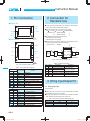
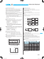
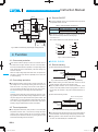
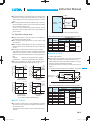
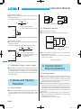
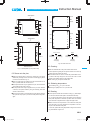
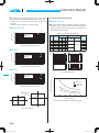
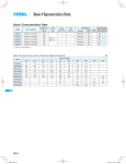
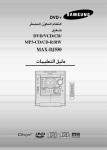
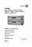
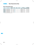
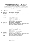
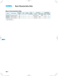
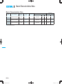
Basic Characteristics Data
Basic Characteristics Data
Model
Circuit method
Switching
frequency
[kHz]
Input
current
[A]
Rated
input fuse
DHS50A
DHS50B
Forward converter
470
*1
DHS100A
DHS100B
Forward converter
470
DHS200A
DHS250B
Forward converter
360
*1 Refer to Specification.
*2 Refer to Instruction Manual.
DHS
DHS-14
Series/Parallel
operation availability
PCB/Pattern
Material
Single
sided
-
Aluminum
*1
-
*1
-
Double
sided
Series
operation
Parallel
operation
Yes
Yes
*2
Aluminum
Yes
Yes
*2
Aluminum
Yes
Yes
*2
DC-DC Converters Bus Converter.Power Module Type
Instruction Manual
1
Pin Connection
DHS-16
2
Connection for Standard Use
DHS-16
3
Wiring Input/Output Pin
DHS-16
4
5
6
7
3.1
Wiring input pin
DHS-16
3.2
Wiring output pin
DHS-17
Function
DHS-18
4.1
Overcurrent protection
DHS-18
4.2
Overvoltage protection
DHS-18
4.3
Thermal protection
DHS-18
4.4
Remote ON/OFF
DHS-18
4.5
Remote sensing
DHS-18
4.6
Adjustable voltage range
DHS-19
4.7
Withstanding Voltage / Isolation Voltage
DHS-20
Series and Parallel Operation
DHS-20
5.1
Series operation
DHS-20
5.2
Redundancy operation
DHS-20
Implementation-Mounting Method
DHS-20
6.1
Mounting method
DHS-20
6.2
Stress onto the pins
DHS-21
6.3
Cleaning
DHS-21
6.4
Soldering temperature
DHS-21
6.5
Derating
DHS-21
6.6
Heat sink(Optional parts)
DHS-22
Lifetime expectancy depends on
stress by temperature difference
DHS-23
DHS-15
DHS
DC-DC Converters Bus Converter . Power Module Type
1 Pin Connection
2 Connection for
Standard Use
¿DHS50/100
-VIN 3
RC 2
Instruction Manual
6 -VOUT
¡In order to use the power supply, it is necessary to wire as shown
in Fig.2.1 and external components in table2.1.
5 TRM
¡Short the following pins to turn on the power module.
-VIN RC, +VOUT +S, and -VOUT -S (DHS200/250)
4 +VOUT
Reference: 4.4
4.5
+VIN 1
2-FG
”Remote ON/OFF”
”Remote sensing”
¡The DHS Series handles only the DC input.
Avoid applying AC input directly.
It will damage the power supply.
¿DHS200/250
¡Operate with the conduction cooling(e.g. heat radiation from the
aluminum base plate to the attached heat sink).
Reference: 6.5
8 -VOUT
”Derating”
-VIN 3
Heatsink
7 -S
6 TRM
RC 2
5 +S
F1
Cin
DC
Noise
input
filter
+S
+VIN +VOUT
Co
-VIN
+VIN 1
RC
4 +VOUT
+
CY
Load
-VOUT
FG
-S
+S, -S : DHS200/250
Fig.2.1 Connection for Standard Use
4-FG
Fig.1.1 Pin Connection (bottom view)
DHS
Table 1.1 Pin Connection and function
No.
DHS50/100 DHS200/250
1
1
2
2
3
3
4
4
5
6
5
7
8
6
No.
DHS50/100 DHS200/250
1
1
2
2
3
3
4
4
5
6
5
7
8
6
DHS-16
Pin Connection
+VIN
RC
-VIN
+VOUT
+S
TRM
-S
-VOUT
Mounting hole
Pin Connection
+VIN
RC
-VIN
+VOUT
+S
TRM
-S
-VOUT
Mounting hole
Function
+DC input
Remote ON/OFF
-DC input
+DC output
+Remote sensing
Adjustment of output voltage
-Remote sensing
-DC output
Mounting hole
Reference
3.1 Wiring input pin
4.4 Remote ON/OFF
3.1 Wiring input pin
3.2 Wiring output pin
4.5 Remote sensing
4.6 Adjustable voltage range
4.5 Remote sensing
3.2 Wiring output pin
6.1 "Mounting hole"
No.
1
2
3
4
5
6
Symbol
F1
CY
Cin
Co
-
Table 2.1 External components
component
Reference
Input fuse
3.1 (1) ”External fuse”
Primary decoupling capacitor 3.1 (2) ”Noise filter/
Noise filter
Decoupling capacitor”
External capacitor on the input side 3.1 (3) ”External capacitor on the input side”
External capacitor on the output side 3.2 ”Wiring output pin”
Heatsink
6.5 ”Derating”
3 Wiring Input/Output Pin
3.1 Wiring input pin
(1) External fuse
¡Fuse is not built-in on input side. In order to protect the unit, install
the normal blow type fuse on input side.
¡When the input voltage from a front end unit is supplied to multiple
units, install the normal blow type fuse in each unit.
Table 3.1 Recommended fuses (Normal-blow type)
Model
Rated current
Model
Rated current
DHS50A/DHS100A
3.15A
DHS50B/DHS100B
1.6A
DHS200A
5A
DHS250B
3.15A
DC-DC Converters Bus Converter . Power Module Type
Instruction Manual
(2) Noise filter/Decoupling capacitor
(5) Operation with AC input
¡Install an external noise filter and a decoupling capacitor CY for
low line-noise and for stable operation of the power supply.
¡The DHS series handles only for the DC input.
A front end unit(AC/DC unit) is required when the DHS series is
¡Install a correspondence filter, if a noise standard meeting is required or if the surge voltage may be applied to the unit.
¡Install a primary decoupling capacitor CY, with more than 470pF,
near the input pins(within 50mm from the pins).
¡When the total capacitance of the primary decoupling capacitor is
more than 8800pF, the nominal value in the specification may not
operated with AC input.
(6) Reverse input voltage protection
¡Avoid the reverse polarity input voltage. It will break the power
supply.
It is possible to protect the unit from the reverse input voltage by
installing an external diode.
be met by the Hi-Pot test between input and output.
In this case, it is that a capacitor should be installed between output and FG.
DC
(3) External capacitor on the Input side.
YES
¡Install an external capacitor Cin between +VIN and -VIN input pins
for low line-noise and for stable operation of the power supply.
DHS50A/100A
DHS200A
DHS
Load
DHS
Load
AC
DHS50B/100B/250B : more than 0.1 F
*When the line inductance is high or ambient temperature is
lower than -20C, please increase Cin value more than the
AC
/DC
YES
value indicated above.
¡When the line impedance is high or the input voltage rise quickly
at start-up(less than 10 s), install a capacitor Cin between +VIN
Fig.3.3 Use with AC input
(a)
(b)
and -VIN input pins(within 50mm from pins).
+VIN
DC IN
-VIN
DHS50B/100B : more than 10 F
: more than 22 F
DHS250B
Load
AC
NO
: more than 22 F *
: more than 47 F *
DHS
(4) Input voltage range/Input current range
+VIN
DC IN
-VIN
Fig.3.4 Reverse input voltage protection
¡The specification of input ripple voltage is shown as below.
Ripple voltage DHS50A/100A/200A : less than 10Vp-p
DHS50B/100B/250B : less than 20Vp-p
¡Make sure that the voltage fluctuation, including the ripple voltage,
will not exceed the input voltage range.
¡Use a front end unit with enough power, considering the start-up
current Ip of this unit.
3.2 Wiring output pin
DHS
¡Install an external capacitor Co between +VOUT and -VOUT pins
for stable operation of the power supply.
Recommended capacitance of Co is shown in Table 3.2.
¡Select the high frequency type capacitor. Output ripple and startup waveform may be influenced by ESR ESL of the capacitor and
Ripple
voltage
time
t
Fig.3.1 Input voltage ripple
Input current [A]
Input voltage range
lp
Input voltage range
Input voltage [V]
the wiring impedance.
¡Install a capacitor Co near the output pins(within 50mm from the
pins).
Table 3.2 Recommended capacitance Co [ F]
Model
Output voltage (V)
3.3
5
7.5
12
15
24
28
48
Temparature of Base plate
Tbp=0 +100
Tbp=-40 +100
DHS50/100 DHS200/250 DHS50/100 DHS200/250
2200
2200
2200X3 2200X3
2200
2200
2200X3 2200X3
2200
2200X3
470
1000
470X3 1000X3
470
1000
470X3 1000X3
220
470
220X3
470X3
220
470
220X3
470X3
330
330X3
¡The specified ripple and ripple noise are measured by the method
introduced in Fig. 3.5.
Input voltage [V]
Fig.3.2 Input current characteristics
DHS-17
DC-DC Converters Bus Converter . Power Module Type
100mm
2200pF
FG
4.4 Remote ON/OFF
Measuring board
+S
¡The remote ON/OFF function is incorporated in the input circuit
and operated with RC and -VIN.
+VIN +VOUT
DC
input
Cin
+
Co
RC
+
C1
Table 4.1 Remote ON/OFF Specifications
Load
ON/OFF logic
-VIN
-VOUT
FG
-S
Negative
2200pF
Oscilloscope
BW:100MHz
R
Instruction Manual
1.5m 50
Coaxial Cable
C R=50
C=0.01 F +S, -S : DHS200/250
Between RC and -VIN
L level(0 - 1.2V) or short
H level(3.5 - 7.0V) or open
Output voltage
ON
OFF
¡When RC is at low level, a current of 0.5mA typ will flow out.
When Vcc is used, keep it within the following rage:
3.5 [ VCC [ 7V.
When remote ON/OFF is not used, short RC and -VIN.
C1:3.3 - 15V 10 F
24 - 28V 4.7 F
48V
2.2 F
Vcc
RC
RC
-VIN
Fig.3.5 Method of Measuring Output Ripple and Ripple Noise
-VIN
Opto coupler
RC
-VIN
4 Function
Transistor
RC
-VIN
IC
Relay
Fig. 4.1 RC Connection Example
4.1 Overcurrent protection
¡Over Current Protection (OCP) is built in and works at 105% of
the rated current or higher. However, use in an over current situation must be avoided whenever possible. The output voltage of the
¿DHS200, DHS250
4.5 Remote sensing
(1) When Remote Sensing is Not Used
power module will recover automatically if the fault causing over
DHS200
DHS250
current is corrected.
DHS
+S
When the output voltage drops after OCP works, the power mod-
+VOUT
ule enters a ”hiccup mode” where it repeatedly turns on and off at
-VOUT
-S
a certain frequency.
4.2 Overvoltage protection
¡Over Voltage Protection (OVP) is built in. When OVP works, output voltage can be recovered by shutting down DC input for at
least one second or by turning off the remote control switch for
one second without shutting down the DC input. The recovery
+
Load
Co
Short at pin root
Fig. 4.2 When Remote Sensing is Not Used (DHS200/250)
¡When remote sensing is not used, make sure +VOUT and +S are
shorted, and that -VOUT and -S are shorted as well.
¡Keep the patterns between +S and +VOUT and between -S and
-VOUT as short as possible. Avoid a looping pattern. If noise en-
time varies according to input voltage and input capacitance.
ters the loop, the operation of the power module will become un-
Remarks:
stable.
Note that devices inside the power module may fail when a volt-
(2) When Remote Sensing is Used
age greater than the rated output voltage is applied from an exter-
Wire as close as possible
nal power supply to the output terminal of the power module. This
could happen in in-coming inspections that include OVP function
test or when voltage is applied from the load circuit. OVP can be
tested by using the TRM terminal. Consult us for details.
4.3 Thermal protection
¡Over Temperature Protection (OTP) is built in. If the base plate
temperature exceeds 100C, OTP will work, causing the output
voltage to drop. Output voltage can be recovered by shutting
down DC input for at least one second or by turning RC off for one
second without shutting down the DC input.
DHS-18
DHS200
DHS250
+S
+VOUT
-VOUT
-S
+
Co
Load
Fig. 4.3 When Remote Sensing is Used (DHS200/250)
¡Using remote sensing with long wires may cause output voltage to
become unstable. Consult us if long sensing wiring is necessary.
¡Sensing patterns or wires should be as short as possible. If wires
are used, use either twisted-pair or shielded wires.
DC-DC Converters Bus Converter . Power Module Type
Instruction Manual
¡Use wide PCB patterns or thick wires between the power module
and the load. Line drop should be kept less than 0.3V. Make sure
Output
+Vout
External Resistor
R1
output voltage from the power module stays within the specified
range.
1
DHS50
DHS100
¡If the sensing patterns are shorted by mistake, a large current may
flow and damage the pattern. This can be prevented by installing
TRM
3
Load
External Resistor
R2
fuses or resistors close to the load.
-Vout
As wiring or load impedance may generate oscillation or large
External VR 1
2 5kW
fluctuations in output voltage, make sure enough evaluation is
given in advance.
Fig. 4.5 Connecting External Devices (DHS50, DHS100)
4.6 Adjustable voltage range
Table 4.2 Recommended Values of External Resistors (DHS50, DHS100)
¡Output voltage between +VOUT and -VOUT can be adjusted by
connecting external resistors to TRM.
¡When the output voltage adjustment is not used, open the TRM
pin respectively.
¡When the output voltage adjustment is used, note that the overvoltage protection circuit operates when the output voltage sets
too high.
¡The wiring to the potentiometer should be as short as possible.
As the ambient temperature fluctuation characteristics deteriorates
depending on the types of resistors and potentiometers used,
please use resistors and potentiometers of the following specifica-
No.
Adjustable Range
VOUT±5%
VOUT±10%
R1
R2
R1
R2
5.1kW
3.3kW
12kW
8.2kW
15kW
10kW
3.3kW
2.2kW
22kW
15kW
39kW
27kW
47kW
33kW
Output
Voltage
1
2
3
4
5
6
3.3V
5V
12V
15V
24V
28V
¿DHS200, DHS250
tions:
(1) Output voltage adjusting
Resistors ............. Metal film type, coefficient less than ±100ppm/C
Potentiometers ... Cermet type, coefficient less than ±300ppm/C
¡Output voltage can be adjusted by connecting an external potentiometer (VR1) and resistors (R1 and R2) as shown in Fig. 4.6.
5V
120
Others
110
90
0
0
60
Adjustment range [%]
Adjustment range [%]
¡When the input voltage is 60 - 66VDC or 200 - 250VDC, the output voltage adjustment range becomes as shown in fig . 4.4.
66
Adjustment range [%]
Others
110
100
0
Table 4.3.
Consult us if the power module is used in a different configuration.
60
0
0
200
250
Control Amp. of
rated voltage
60
66
Input voltage [V]
DHS50B, DHS100B
-
RA
3kW
2.495V
TRM 2
+
RC
10W
R2
-S
R1
1
VR1
5kW
3
-VOUT
Fig. 4.6 Connecting External Parts (DHS250)
Others
110
Table 4.3 Recommended Values of External Resistors (DHS250)
No.
60
0
+S
RB
3kW
3.3, 5V
120
0
+VOUT
DHS200
DHS250
100
100
90
0
Recommended values for external components are shown in
Input voltage [V]
DHS200A
Adjustment range [%]
3.3, 5V
Others
110
Input voltage [V]
DHS50A, DHS100A
120
5V
120
Output voltage will increase if the resistance between 1 and 2 is
reduced by turning the potentiometer clockwise.
200
250
Input voltage [V]
DHS250B
Fig. 4.4 Output Voltage Adjustment Range
¿DHS50, DHS100
¡To increase the output voltage, turn the potentiometer clockwise
and connect in such a way that the resistance value between 2
1
2
3
4
5
6
7
8
Output
Voltage
3.3V
5V
7.5V
12V
15V
24V
28V
48V
Adjustable Range
VOUT±5%
VOUT±10%
R1
R2
R1
R2
2.4kW
2.4kW
5.6kW
5.6kW
10kW
10kW
18kW
18kW
12kW
8.2kW
24kW
24kW
43kW
43kW
47kW
47kW
91kW
91kW
and 3 becomes small.
To decrease the output voltage, turn the potentiometer counterclockwise.
DHS-19
DHS
DC-DC Converters Bus Converter . Power Module Type
Instruction Manual
(a)
(b)
The external resistor (RD) is calculated the following equation.
VOD
- 0.01
VOR
RD=
[kW]
VOD
1.0 VOR
1.51X
DHS200 +VOUT
DHS250
+S
VOR :Rated output voltage[V]
VOD :Output voltage needed to set up[V]
TRM
Load
Power
Supply
Power
Supply
Power
Supply
Load
¡By connecting the external resistor (RD), output voltage becomes
adjustable to decrease.
Load
(2) Output voltage decreasing
Power
Supply
Fig. 5.1 Examples of series operation
5.2 Redundancy operation
¡Parallel operation is not possible.
¡Redundancy operation is available by wiring as shown below.
RD
-S
-VOUT
+S
+VOUT
Fig. 4.7 Connection for output voltage decreasing (DHS200/250)
+S
+VOUT
The external resistor (RU) is calculated the following equation.
[
3.0X
DHS200 +VOUT
DHS250
+S
TRM
VOR
VOU
+ 0.01
- 1.51 X
Vref
VOR
VOU
- 1.0
VOR
-S
-VOUT
DHS
I2
-VOUT
-S
]
VOR :Rated output voltage [V]
VOU :Output voltage needed to set up [V]
Vref :Refarence voltage [V]
Vref=2.495 [V]
Load
¡By connecting the external resistor (RU), output voltage becomes
adjustable to increase.
RU
I3
-VOUT
-S
(3) Output voltage increasing
RU=
I1
+S, -S : DHS200/250
Fig. 5.2 Example of Redundancy Operation
¡Even a slight difference in output voltage can affect the balance
between the values of I1 and I2.
Please make sure that the value of I3 does not exceed the rated
current of a power supply.
I3
the rated current value
Fig. 4.8 Connection for output voltage increasing (DHS200/250)
4.7 Withstanding Voltage / Isolation Voltage
¡When testing the withstanding voltage, make sure the voltage is
increased gradually. When turning off, reduce the voltage gradual-
6 ImplementationMounting Method
ly by using the dial of the hi-pot tester. Do not use a voltage tester
with a timer as it may generate voltage several times as large as
the applied voltage.
6.1 Mounting method
¡The unit can be mounted in any direction. When two or more
power supplies are used side by side, position them with proper
5 Series and Parallel
Operation
intervals to allow enough air ventilation. Aluminum base plate
temperature around each power supply should not exceed the
temperature range shown in derating curve.
¡Avoid placing the DC input line pattern lay out underneath the unit,
it will increase the line conducted noise. Make sure to leave an
ample distance between the line pattern lay out and the unit. Also
5.1 Series operation
¡Series operation is available by connecting the outputs of two or
more power supplies, as shown below. Output current in series
connection should be lower than the lowest rated current in each
unit.
avoid placing the DC output line pattern underneath the unit because it may increase the output noise. Lay out the pattern away
from the unit.
¡High-frequency noise radiates directly from the unit to the atmosphere. Therefore, design the shield pattern on the printed circuit
board and connect its one to FG.
The shield pattern prevents noise radiation.
DHS-20
DC-DC Converters Bus Converter . Power Module Type
Instruction Manual
Shield pattern
-VOUT
TRM
-VOUT
+VOUT
-VIN
RC
+VIN
+VOUT
-VIN
DHS50, DHS100
+VIN
-VOUT
-VIN
DHS50, DHS100
-S
Shield pattern
TRM
RC
+S
+VIN
+VOUT
-VOUT
-VIN
DHS200, DHS250
+VOUT, -VOUT
+VOUT
+VIN
Less than
39.2N(4kgf)
Less than
39.2N(4kgf)
Others
Less than
19.6N(2kgf)
Less than
39.2N(4kgf)
Less than
19.6N(2kgf)
Less than
19.6N(2kgf)
Fig. 6.2 Stress onto Pins
DHS200, DHS250
Fig. 6.1 Shield pattern lay out (bottom view)
6.2 Stress onto the pins
¡Applying excessive stress to the input or output pins of the power
module may damage internal connections. Avoid applying stress
in excess of that shown in Fig. 6.1.
¡Input and output pins are soldered onto the internal PCB. Do not
bend or pull the leads with excessive force.
¡As unexpected stress may be applied to the pins, set the diameter
of the PCB mounting hole at 3.5mm.
¡As unexpected stress may be applied to the pins from vibration
or shock, fix the power module by using the mounting holes with
screws to reduce stress.
¡Fix the power module to the PCB with the screws before soldering
the input and output pins to prevent the PCB pattern being damaged.
6.3 Cleaning
DHS
¡Clean the soldered side of the power module with a brush.
Prevent liquid from getting into the power module. Do not clean by
soaking the power module into liquid.
¡Do not allow solvent to come in contact with product labels or resin cases as this may change the color of the resin case or cause
deletion of the letters printed on the product label.
¡After cleaning, dry the power modules well.
6.4 Soldering temperature
¡Flow soldering: 260C for up to 15 seconds.
¡Soldering iron (26W): 450C for up to 5 seconds.
6.5 Derating
¡Use the power modules with conduction cooling (e.g. heat dissipation from the aluminum base plate to the attached heat sink).
Fig. 6.3 shows the derating curves with respect to the aluminum
base plate temperature. Note that operation within the hatched
areas will cause a significant level of ripple and ripple noise.
¡Please measure the temperature on the aluminum base plate
edge side when you cannot measure the temperature of the center part of the aluminum base plate.
In this case, please take 5deg temperature margin from the derating characteristic of Figure 6.3.
DHS-21
DC-DC Converters Bus Converter . Power Module Type
¡It is necessary to note the thermal fatigue life by power cycle.
Please reduce the temperature fluctuation range as much as possible when the up and down of the temperature are frequently
generated.
Instruction Manual
6.6 Heat sink(Optional parts)
¿DHS50, DHS100
¡The power module works with conduction cooling and needs heat
dissipation using heat sinks. Optional heat sinks are available for
Contact us for more information on cooling methods.
¿DHS50, DHS100
DHS Series. Refer to Table 6.1 and Table 6.2 for details on the
thermal resistance of heat sinks.
2
1
Table 6.1 Types of Heat Sinks Available
1DHS100B24,28
2Others
Size[mm]
50
-20
0
20
40
60
(85)
80
100 110
Aluminum base plate temperature Tc [C]
¿DHS200
1
2
3
4
5
6
F-QB-F1
F-QB-F2
F-QB-F3
F-QB-F4
F-QB-F5
F-QB-F6
H
W
D
12.7
12.7
25.4
25.4
38.1
38.1
58.4
58.7
58.4
58.7
58.4
58.7
37.6
37.3
37.6
37.3
37.6
37.3
W
100
-20
0
20
60
(75) (85)
80
100 110
¿DHS250
Fig.6.4 Heat Sink Types
2
1DHS250B12,48
2Others
-20
0
20
40
10
1
50
60
(75) (85)
80
100 110
Aluminum base plate temperature Tc [C]
Tc
Measuring point
Thermal resistance(C/w)
Load factor [%]
Vertical
Horizontal
100
15
0
-40
5.0
D
40
Aluminum base plate temperature Tc [C]
DHS
7.5
Horizontal
Vertical
Horizontal
Refer Fig.6.5
Vertical
Horizontal
Vertical
2
50
15
0
-40
14.0
Style
W
1
1DHS200A05
2Others
Thermal resistance[C/W]
Convection
Forced Air
(0.1m/s)
H
Load factor [%]
Model
D
15
0
-40
No.
H
Load factor [%]
100
8
F-QB -F1/F2
F-QB -F3/F4
F-QB -F5/F6
6
4
2
0
0.0
0.5
1.0
1.5
2.0
Wind velocity(m/s)
2.5
Fig.6.5 Thermal Resistance of Heat Sink(Forced Air)
DHS50, DHS100
DHS200, DHS250
Fig.6.3 Derating Curve
DHS-22
3.0
DC-DC Converters Bus Converter . Power Module Type
¿DHS200, DHS250
Table 6.2 Types of Heat Sinks Available
Size[mm]
No.
Model
1
2
3
4
5
6
F-CBS-F1
F-CBS-F2
F-CBS-F3
F-CBS-F4
F-CBS-F5
F-CBS-F6
H
W
D
12.7
12.7
25.4
25.4
38.1
38.1
57.9
58.4
57.9
58.4
57.9
58.4
61.5
61.0
61.5
61.0
61.5
61.0
Thermal resistance[C/W]
Convection
Forced Air
(0.1m/s)
7.5
4.6
3.0
Style
Horizontal
Vertical
Horizontal
Refer Fig.6.7
Vertical
Horizontal
Vertical
W
Instruction Manual
7 Lifetime expectancy depends on
stress by temperature difference
¡Regarding lifetime expectancy design of solder joint, following
contents must be considered.
It must be careful that the soldering joint is stressed by temperature rise and down which is occurred by self-heating and ambient
temperature change.
The stress is accelerated by thermal-cycling, therefore the tem-
W
perature difference shoud be minimized as much as possible if
temperature rise and down is occurred frequently.
D
D
¡Product lifetime expectancy depends on the aluminum base plate
central temperature difference (DTc) and number of cycling in a
day is shown in Fig.7.1.
If the aluminum base plate center part temperature changes frequently by changing output load factor etc., the above the lifetime
expectancy design should be applied as well.
Vertical
Fig. 6.6 Heat Sink Types
Thermal resistance(C/w)
6
5
F-CBS-F1/F2
F-CBS -F3/F4
F-CBS-F5/F6
4
3
Lifetime expectancy [years]
Horizontal
H
H
Please contact us for details.
10
5
1time
2times
3times
4times
5times
ON/OFF /1day
ON/OFF /1day
ON/OFF /1day
ON/OFF /1day
ON/OFF /1day
DHS
0
25
30
35
40
45
50
55
60
65
70
The aluminum base plate central temperature differenceDTc [C]
Fig7.1 Lifetime expectancy against rise/fall temperature difference
2
1
0
0.0
0.5
1.0
1.5
2.0
Wind velocity(m/s)
2.5
3.0
Fig.6.7 Thermal Resistance of Heat Sink(Forced Air)
DHS-23