1
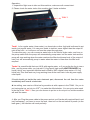
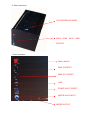
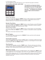
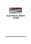
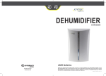
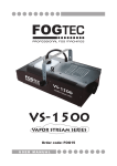
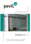
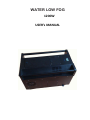
WATER LOW FOG
1200W
USER’s MANUAL
WARNING FOR YOUR OWN SAFETY, PLEASE READ THIS USER MANUAL CAREFULLY
BEFORE YOUR INITIAL START-UP!
CAUTION!
Keep this equipment away from rain,
moisture and liquids.
SAFETY INSTRUCTIONS
Every person involved with the installation, operation & maintenance of this equipment
should:
---Be competent
---Follow the instructions of this manual
CAUTION!
TAKE
CARE
USING
THIS
EQUIPMENT!
HIGH VOLTAGE-RISK OF ELECTRIC SHOCK!!
Before your initial start-up, please make sure that there is no damage caused during
transportation. Should there be any, consult your dealer and do not use the equipment.
To maintain the equipment in good working condition and to ensure safe operation, it is
necessary for the user to follow the safety instructions and warning notes written in this
manual.
Please note that damages caused by user modifications to this equipment are not subject
to warranty.
Important
The manufacturer will not accept liability for any resulting damages caused by the
non-observance of this manual or any unauthorized modification to the equipment.
●Never let the power-cable come into contact with other cables. Handle the power-cable
and all mains voltage connections with particular caution!
● Never remove warning or informative labels from the equipment.
● Do not open the equipment and do not modify the equipment.
● Only use the equipment indoors.
● Do not expose to flammable sources or gases.
●Always disconnect the power from the mains when equipment is not in use or before
cleaning! Only handle the power-cable by the plug. Never pull out the plug by pulling the
power-cable.
● Make sure that the available voltage is AC220V.
● Make sure that the power-cable is never crimped or damaged. Check the equipment
and the power-cable periodically.
● If the equipment is dropped or damaged, disconnect the mains power supply
immediately. Have a qualified engineer inspect the equipment before operating again.
● If the equipment has been exposed to drastic temperature fluctuation (e.g. after
transportation), do not switch it on immediately. The arising condensation might
damage the equipment. Leave the equipment switched off until it has reached room
temperature.
● If your product fails to function correctly, discontinue use immediately. Pack the unit
securely (preferably in the original packing material), and return it to your dealer for
service.
● Only use fuses of same type and rating.
● Repairs, servicing and power connection must only be carried out by a qualified
technician. THIS UNIT CONTAINS NO USER SERVICEABLE PARTS.
OPERATING DETERMINATIONS
If this equipment is operated in any other way, than those described in this manual, the
product may suffer damage and the warranty becomes void. Incorrect operation may lead
to danger e.g. short-circuit, burns, electric shocks etc.
Do not endanger your own safety and the safety of others! Incorrect installation or use can
cause serious damage to people and property.
Before filling the unit disconnects the mains. Never fill with hot liquids. Only use liquid as
our manual suggest, as this machine has two tanks with different requirements on each
tank.
Always make sure there is liquid the tank but no more than the MAX LEVEL. This machine
is different with normal fog or low fog machine, as it cannot work with over level liquid if
your pump switch is off. Operating this smoke machine without any liquid inside will cause
damage to the inside part though this machine will stop working and alarm if liquid lower
than required level.
Operate the unit only after you have familiarized yourself with its functions, Do not permit
operation by persons not qualified for operating the unit and always drain the tank and use
the original packaging if the unit is to be transported.
Operation:
1, Unpack the flight case to take out this machine, make sure all comes intact.
2, Please check the water tanks, this machine has 2 tanks as below
TANK 1 TANK 2 Tank 1. Is for regular water (clean water), no chemicals or other fog liquid is allowed to put
inside, just regular water. You can pour inside to tank but never higher than the output of
mist at the front , or it will pour out from the output through pipe;
To make this easy, you can connect a water hose to the faucet/ hydro valve, and turn on
the pump switch then the pump will automatically pump water into the water tank and the
pump will stop working when the water reaches the Max level(same level of the output of
mist), but will automatically pump in water when the water is lower than the Min level
required.
Tanks 2 is a small bottle that can full fill with regular water, or if you prefer the fog to rise a
little , and fog more white, you just add 1% fog liquid( high quality WATER-BASED fog
liquid), this is very important that this tank is filled by 99% regular clean water +1% fog
liquid only! This tank lasts very long working time as the main tank is the big one supply
most liquid..
If liquid should get inside the main electronic part, disconnect the unit from the mains
immediately and consult a technician.
3. Ice adding, new version of this low fog machine is with a space in the TANK 1 for you to
put ice(regular ice, not dry ice /CO2 ) to make the effects better. You can put a wire mesh
in the top of the TANK1 , then you can choose to put ice or do not put ice, but the machine
will work the same.
4. After you Plug the power cable to the power socket, put 2 tanks with required liquid, and
ice(if necessary), you have to cover the tank , then turn on the red switch of power (on the
back gear ), the machine will work perfectly.
5. Gear instruction:
LCD CONTROLLER PANEL
BACK GEAR WITH DMX SOCKETS Zoom as below:
Power Switch DMX IN SOCKET DMX OUT SOCKET FUSE
POWER INPUT SOCKET
WATER VALVE INPUT
WATER OUTPUT 6. LCD controller setting
The LCD DISPLAY on the TOP side is for you to control the fog output as follows:
LCD CONTROLLER PANEL OVER VIEW:
This machine need several minutes
warming up for the first time turning on
the machine, but once it is with power
on, it no need warming up for operation
after that
as it doesn’t use any heater
systems. More control function as
below:
Interval Time Setting
To set the interval times, press the “MENU” button to show Interval on the LCD display.
Now use the “UP” and “DOWN” buttons to increase or decrease the interval times
between each burst. The interval time can be set from 1-900s.
Duration Time Setting
To set the duration times, press the “MENU” button to show Duration on the LCD display.
Now use the “UP” and “DOWN” buttons to increase or decrease the duration between
each burst. The duration time can be set from 1-200s.
Output Volume Setting
To set the output volume, press the “MENU” button to show Output on the LCD display.
Now use the “UP” and “DOWN” buttons to increase or decrease the smoke output each
burst.
The output volume can be set from 0-100%.
Manual Fogging
For manual fog output, simply press the “MANUAL” button and hold until the desired
amount of smoke is emitted.
Constant Burst Operation
To set unit for constant burst, press the “LOCK” button. To stop the constant burst simply
Press the “LOCK” button again. During this operation you can change the volume output
by pressing the “UP” and “DOWN” buttons.
Timer Operation
To use the timer operation, press the “TIMER” button. The timer will now work with the
Interval, Duration and Volume setting that you have previously set. To change any of the
settings for these options please follow the steps on the previous page.
DMX Address Setting
There are two methods to set the units DMX address: one is pressing the “MENU” button
to show DMX-512 on the LCD display. Now use the “UP” and “DOWN” buttons to set the
desired DMX address from 001-512, another is setting DMX Address through DIP Switch
as usually, but the DMX Address set through DIP Switch has priority if two methods
setting at same time.
For DMX function, please refer to the DMX chart below:
DMX Chart
Channel
Value
Function
1
0-255
Manual fogging (low - high output)
OPERATION
After switching on via the On/off switch the controllers the LCD display will show “READY
TO FOG” and the unit is now ready for operation.
DMX Control Mode
Operating in a DMX control mode environment gives the user the greatest flexibility when
it comes to customizing or creating a show. In this mode you will be able to control each
individual trait of the fixture and each fixture independently.
When under DMX mode with DMX cable connected, MANUAL IS INVALID; If you
need to use MANUAL you must unplug the DMX cable.
Setting the DMX address
The DMX mode enables the use of a universal DMX controller. Each fixture requires a
“start address” from 1- 511. A fixture requiring one or more channels for control begins to
read the data on the channel indicated by the start address.
For example, a fixture that occupies or uses 7 channels of DMX and was addressed to
start on DMX channel 100, would read data from channels: 100,101,102,103,104,105 and
106. Choose a start address so that the channels used do not overlap. E.g. the next unit in
the chain starts at 107.
DMX-512:
• DMX (Digital Multiplex) is a universal protocol used as a form of communication between
intelligent fixtures and controllers. A DMX controller sends DMX data instructions form the
controller to the fixture.
DMX data is sent as serial data that travels from fixture to fixture via the DATA “IN” and
DATA “OUT” XLR terminals located on all DMX fixtures (most controllers only have a data
“out” terminal).
DMX Linking
• DMX is a language allowing all makes and models of different manufactures to be linked
together and operate from a single controller, as long as all fixtures and the controller are
DMX compliant.
To ensure proper DMX data transmission, when using several DMX fixtures try to use the
shortest cable path possible. The order in which fixtures are connected in a DMX line does
not influence the DMX addressing. For example; a fixture assigned to a DMX address of 1
may be placed anywhere in a DMX line, at the beginning, at the end, or anywhere in the
middle.
When a fixture is assigned a DMX address of 1, the DMX controller knows to send DATA
assigned to address 1 to that unit, no matter where it is located in the DMX chain.
DATA Cable (DMX cable) requirements (for DMX operation):
• The WATER LOW FOG can be controlled via DMX-512 protocol. The DMX address is
set on the back of the unit. Your unit and your DMX controller require a standard 3-pin
XLR connector for data input/output as follows:.
Also remember that DMX cable must be daisy chained and cannot be split.
CLEANING AND MAINTENANCE
DANGER TO LIFE!
Disconnect from the mains before starting maintenance
We recommend a frequent cleaning of the unit. Please use a soft lint-free and moistened
cloth. Never use alcohol or solvents! Clean the output and the inside of Tank 1 always.
Fog liquid used for the 1% of Tank 2 we recommend are non-hazardous to the
environment and can be disposed of via the sewage system.
There are no user serviceable parts inside this unit except for the fuse. Maintenance and
service operations are only to be carried out by authorized dealers.
REPLACING THE FUSE
Only replace the fuse with a fuse of same type and rating.
Before replacing the fuse, disconnect from the mains.
Procedure:
Step 1: Open the fuse holder on the rear panel with a suitable screwdriver.
Step 2: Remove the old fuse from the fuse holder
Step 3: Install the new fuse in the fuse holder
Step 4: Replace the fuse holder in the housing.
Should you need any spare parts, only use genuine parts.
If defective, please dispose of
the unusable unit in accordance with the current legal regulations. Should you have any
further questions, please contact your dealer.
Technical Specifications
Fog output
1,0000 cu.ft per minute
Warm up time
First time 5 minutes
Fuse:
10A/250V
Power consumption
1200W
Power supply
220V
Dimensions
Weight
66*40*44CM
40Kgs