1
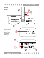
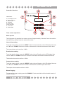
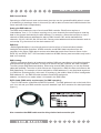
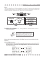
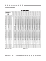
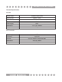
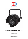
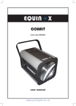
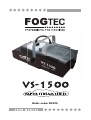
Order code: FOG15
WARNING
FOR YOUR OWN SAFETY, PLEASE READ THIS USER MANUAL CAREFULLY
BEFORE YOUR INITIAL START-UP!
CAUTION!
Keep this equipment away from rain,
moisture and liquids.
SAFETY INSTRUCTIONS
Every person involved with the installation, operation & maintenance of this
equipment should:
Be competent
Follow the instructions of this manual
CAUTION! TAKE CARE USING THIS EQUIPMENT!
HIGH VOLTAGE-RISK OF ELECTRIC SHOCK!!
Before your initial start-up, please make sure that there is no damage caused
during transportation. Should there be any, consult your dealer and do not use
the equipment.
To maintain the equipment in good working condition and to ensure safe operation, it is necessary
for the user to follow the safety instructions and warning notes written in this manual.
Please note that damages caused by user modifications to this equipment are not
subject to warranty.
IMPORTANT:
The manufacturer will not accept liability for any resulting damages caused by the
non-observance of this manual or any unauthorised modification to the equipment.
• Never let the power-cable come into contact with other cables. Handle the power-cable
and all mains voltage connections with particular caution!
• Never remove warning or informative labels from the equipment.
• Do not open the equipment and do not modify the equipment.
• Only use the equipment indoors.
• Do not expose to flammable sources or gases.
• Always disconnect the power from the mains when equipment is not in use or before
cleaning! Only handle the power-cable by the plug. Never pull out the plug by pulling the
power-cable.
• Make sure that the available voltage is between 220v/240v.
• Make sure that the power-cable is never crimped or damaged. Check the equipment and
the power-cable periodically.
• If the equipment is dropped or damaged, disconnect the mains power supply immediately.
Have a qualified engineer inspect the equipment before operating again.
• If the equipment has been exposed to drastic temperature fluctuation (e.g. after
transportation), do not switch it on immediately. The arising condensation might damage
the equipment. Leave the equipment switched off until it has reached room temperature.
• If your product fails to function correctly, discontinue use immediately. Pack the unit
securely (preferably in the original packing material), and return it to your Prolight dealer
for service.
• Only use fuses of same type and rating.
• Repairs, servicing and power connection must only be carried out by a qualified
technician. THIS UNIT CONTAINS NO USER SERVICEABLE PARTS.
• WARRANTY: One year from date of purchase.
OPERATING DETERMINATIONS
If this equipment is operated in any other way, than those described in this manual,
the product may suffer damage and the warranty becomes void.
Incorrect operation may lead to danger e.g. short-circuit, burns, electric shocks etc.
Do not endanger your own safety and the safety of others!
Incorrect installation or use can cause serious damage to people and property.
Before filling the unit disconnect the mains. Never fill with hot liquids.
Only use high quality, water based smoke fluid recommended by the manufacturer. Other smoke fluids
may cause clogging and void the warranty.
Always make sure there is sufficient smoke fluid in the tank. Operating this smoke machine without
smoke fluid will cause damage to the pump as well as over heating of the heater.
Operate the unit only after you have familiarized yourself with its functions, Do not permit operation by
persons not qualified for operating the unit and always drain the tank and use the original packaging if the
unit is to be transported.
OV E RV I E W
Overview:
VP-3000
Identification:
A, Hanging Bracket
B, Fog fluid container
C, Fluid pipe
D, Tightening Knobs
E, Output nozzle
F, On/off switch
G, Power input
H, DMX input
I, DMX output
J, Wireless remote input
O P E R AT I O N
Controller Overview
Identification:
A, LCD display screen
B, Securing screws
C, Menu button
D, Up button
E, Down button
F, Manual button
G, Lock button
H, Timer button
Timer remote operations:
Warm up time
This high power fog machine has a warm up time of approximately 3 minutes. Once the machine
has warmed up, please follow the instructions below.
Interval time setting
To set the interval times, press the “MENU” button to show Interval on the LCD display. Now use
the “UP” and “DOWN” buttons to increase or decrease the interval times between each burst.
The interval time can be set from 1-900s.
Duration time setting
To set the duration times, press the “MENU” button to show Duration on the LCD display. Now
use the “UP” and “DOWN” buttons to increase or decrease the duration between each burst.
The duration time can be set from 1-200s.
Output volume setting
To set the output volume, press the “MENU” button to show Output on the LCD display. Now use
the “UP” and “DOWN” buttons to increase or decrease the smoke output each burst.
The output volume can be set from 0-100%.
Manual fogging
For manual fog output, simply press the “MANUAL” button and hold until the desired amount of
smoke is emitted.
O P E R AT I O N
Constant burst operation
To set unit for constant burst, press the “LOCK” button. To stop the constant burst simply press
the “LOCK” button again. During this operation you can change the volume output by pressing the
“UP” and “DOWN” buttons.
Timer operation
To use the timer operation, press the “TIMER” button. The timer will now work with the Interval,
Duration and Volume setting that you have previously set. To change any of the settings for these
options please follow the steps on the previous page.
DMX address setting
To set the units DMX address, press the “MENU” button to show DMX-512 on the LCD display.
Now use the “UP” and “DOWN” buttons to set the desired DMX address from 001-512.
For DMX function, please refer to the DMX chart below.
DMX Chart
Channel
Value
Function
1
0-255
Manual fogging (low - high output)
STARTING OPERATION
The fluid tank of the unit needs to be filled with smoke fluid before switching on.
Always disconnect it from the mains supply as fluid could be spilled.
Only use quality smoke fluids recommended by your dealer. We recommend high quality
smoke fluids. You must not use substances which are classified as
“DANGEROUS WORKING MATERIALS” or “FLAMMABLE FLUIDS”.
If fluid should get inside the main housing, disconnect the unit from the mains immediately and
consult a technician.
OPERATION
Before switching the unit on, please make sure that the LCD timer remote control is connected to
the unit properly.
After switching on via the On/off switch the controllers LCD screen will display “WARMING UP”.
When the unit has reached the correct temperature, the LCD display will show “READY TO FOG”
and the unit is now ready for operation.
DMX SET UP
DMX Control Mode
Operating in a DMX control mode environment gives the user the greatest flexibility when it comes
to customising or creating a show. In this mode you will be able to control each individual trait of the
fixture and each fixture independently.
Setting the DMX address
The DMX mode enables the use of a universal DMX controller. Each fixture requires a
“start address” from 1- 511. A fixture requiring one or more channels for control begins to read the
data on the channel indicated by the start address. For example, a fixture that occupies or uses 7
channels of DMX and was addressed to start on DMX channel 100, would read data from
channels: 100,101,102,103,104,105 and 106. Choose a start address so that the channels used do
not overlap. E.g. the next unit in the chain starts at 107.
DMX-512:
• DMX (Digital Multiplex) is a universal protocol used as a form of communication between
intelligent fixtures and controllers. A DMX controller sends DMX data instructions form the
controller to the fixture. DMX data is sent as serial data that travels from fixture to fixture via the
DATA “IN” and DATA “OUT” XLR terminals located on all DMX fixtures (most controllers only have a
data “out” terminal).
DMX Linking:
• DMX is a language allowing all makes and models of different manufactures to be linked together
and operate from a single controller, as long as all fixtures and the controller are DMX compliant.
To ensure proper DMX data transmission, when using several DMX fixtures try to use the shortest
cable path possible. The order in which fixtures are connected in a DMX line does not influence the
DMX addressing. For example; a fixture assigned to a DMX address of 1 may be placed anywhere
in a DMX line, at the beginning, at the end, or anywhere in the middle. When a fixture is assigned a
DMX address of 1, the DMX controller knows to send DATA assigned to
address 1 to that unit, no matter where it is located in the DMX chain.
DATA Cable (DMX cable) requirements (for DMX operation):
• The VS-1500 can be controlled via DMX-512 protocol. The DMX address is set on the back of the
unit. Your unit and your DMX controller require a standard 3-pin XLR connector for data input/output
(figure 1).
Also remember that DMX cable must be daisy chained and cannot be split.
DMX SET UP
Notice:
• Be sure to follow figures 2 & 3 when making your own cables. Do not connect the cable’s shield
conductor to the ground lug or allow the shield conductor to come in contact with the XLR’s outer
casing. Grounding the shield could cause a short circuit and erratic behaviour.
Special Note: Line termination:
• When longer runs of cable are used, you may need to use a terminator on the last unit to
avoid erratic behaviour.
Termination reduces signal transmission problems
and interferance. it is always advisable to connect a
DMX terminal, (resistance 120 Ohm 1/4 W) between
pin 2 (DMX-) and pin 3 (DMX+) of the last fixture.
Using a cable terminator (part number CABL90) will decrease the possibilities of erratic
behaviour.
5-Pin XLR DMX Connectors:
• Some manufactures use 5-pin XLR connectors for data transmission in place of 3-pin. 5-Pin
XLR fixtures may be implemented in a 3-pin XLR DMX line. When inserting standard 5-pin
XLR connectors in to a 3-pin line a cable adaptor must be used. The Chart below details the
correct cable conversion.
DMX SET UP
Dip switch reference chart
O P E R AT I O N
CLEANING AND MAINTENANCE
DANGER TO LIFE!
Disconnect from the mains before
starting maintenance
We recommend a frequent cleaning of the unit. Please use a soft lint-free and moistened cloth.
Never use alcohol or solvents!
Clean the output nozzle frequently from smoke fluid residues.
The
smoke fluids we recommend are non-hazardous to the environment and can be
disposed of via the sewage system.
There are no user serviceable parts inside this unit except for the fuse. Maintenance and service
operations are only to be carried out by authorized dealers.
REPLACING THE FUSE
Only replace the fuse with a fuse of same type and rating.
Before replacing the fuse, disconnect from the mains.
Procedure:
Step 1: Open the fuse holder on the rear panel with a suitable screwdriver.
Step 2: Remove the old fuse from the fuse holder,
Step 3: Install the new fuse in the fuse holder
Step 4: Replace the fuse holder in the housing.
Should you need any spare parts, only use genuine parts.
If defective, please dispose of the unusable unit in accordance with the current legal regulations.
Should you have any further questions, please contact your dealer.
S P E C I F I C AT I O N S
Technical Specifications
VS-1500
Smoke output
10,000 cu.ft per minute
Warm up time
approx. 7 mins
Tank capacity
Power consumption
Power supply
Dimensions
Weight
1L
1500W
240V
721 x 312 x 262mm
5Kgs
VS-T Controller
Cable length
Connector
Function
Dimensions
Weight:
2.5M
5-pin XLR
Interval, Duration, Output and DMX
139 x 92 x 43mm
0.46Kgs
w w w. p r o l i g h t . c o . u k