1
A License Plate Recognition and Speed Detection System
Leo Cetinski
David Dawson
A Special Project
Submitted in Partial Fulfillment of the
Requirements for the Degree of
Master of Science
In
Computer Information Technology
Department of Computer Science, Management Information Systems, and Industrial
Technology
Central Connecticut State University
New Britain, CT
4/2008
Thesis Advisor: Dr. Farid Farahmand
Contents
I.
II.
III.
Abstract…………………………………………………
Introduction…………………………………………… .
License Plate Recognition Concepts…………………. .
A. LPR Light Source…………………………………..
B. LPR Camera………………………………………...
C. LPR Computer……………………………………...
D. LPR Trigger…………………………………………
IV.
Speed Detection Radar Concepts……………………...
V.
Our System Design and Implementation………………
A. Overview…………………………………………….
B. Components ………………………………………...
1. LPR Components…………………...............
2. Radar Gun…………………………………...
3. Serial Interface Circuit Board..…………….
4. Table of System Components………………
C. LPR Software……………………………………......
1. Instructions for Running the Software……...
2. Software Architecture……………………….
3. Application Layer Algorithms………………
D. Testing……………………………………………......
VI.
Additional Applications……………………………........
VII. State of the Art Commercial Systems………………….
VIII. Conclusion………………………………………..............
IX.
References…………………………………………..........
Appendix A Our LPR/SD System Component Specifications…..
Appendix B Commercial Components……………………..…….
Appendix C Camera Setup Calculations…………………………
2
3
5
7
8
12
19
20
23
30
30
33
33
38
48
51
51
54
55
56
59
64
70
79
81
84
86
94
I. Abstract
Since the 1980’s law enforcement has deployed traffic enforcement camera systems to
monitor roadways for traffic violations. There are a variety of commercially available systems
today that can capture images of vehicles running red lights, passing toll booths without paying,
speeding, or traveling on restricted lanes. “In many cases the LPR unit is added as retrofit in
addition to existing solutions, such as a magnetic card reader or ticket dispenser/reader, in order
to add more functionality to the existing facility (Ref 32)”. Basic systems capture images of
passing vehicles and require human intervention to decipher license plate numbers. A person will
have to analyze the picture containing the traffic violation, decipher the license plate number of
the violating vehicle, and generate the fine for the violation. More advanced systems use image
processing techniques to extract license plate numbers from camera images. This allows traffic
fines to be automatically generated and sent to the appropriate violator without the need for
human intervention. These types of systems are called license plate recognition (LPR) systems or
automatic number plate recognition (ANPR) systems.
The technology for these systems has advanced over the generations. Now whole
networks of traffic cameras are being deployed across cities to continually monitor vehicles on
city roads. Several cities in the United Kingdom including Northampton, Bradford, Stoke and the
City of London have deployed ANPR systems. A push is being made to have all roadways in the
United Kingdom be monitored by ANPR cameras. Currently, information from all traffic
cameras in the United Kingdom is stored in one central repository called the National ANPR
Data Centre. The data stored at this central repository is used in a multitude of ways. Data can
be accessed in real time by police providing a way to locate suspected vehicles in real time. Data
mining techniques are also applied against the central repository providing an endless flow of
3
information. Questions such as “What traveling patterns did a certain criminal have 3 years ago”
can be answered. In the United States, the push for traffic monitoring cameras has not been as
great. Many citizens have criticized the effectiveness, accuracy, and legality of traffic monitoring
cameras. Traffic cameras, however, have made their way in to the U.S. mostly at toll booth and
ez-pass locations. Also, a new network of traffic monitoring cameras is being implemented in
New York City called the “Lower Manhattan Security Initiative”. It will contain hundreds of
license plate readers (along with thousands of other cameras for human surveillance) to flag any
suspect vehicles.
The purpose of this capstone project is to build a functional license plate recognition
system capable of retrieving and recording a vehicle’s license plate number, the speed it was
traveling and the date and time the vehicle was detected. System implementation is to be done at
the prototype level in which desired functionality is limited by the amount of resources available.
Documentation coinciding with this project will describe the project solution. A description of all
system hardware and software components and their specifications will be given. The
documentation will also include a description of the limitations of our system, a description of a
more optimum solution if more resources were available, the test results of our system, a
description of currently available commercial systems, the legality of traffic monitoring cameras,
and a description of other types of applications our system could be extended to. Our project
application will help make our roads safer. It will provide a tool for law enforcement to monitor
speeding vehicle activity and assist in tracking down violators. License plate recognition is now
a viable mature technology and is being used in a variety of applications today.
4
II. Introduction
The purpose of this project was to build a system capable of automatically recording the
speed and license plate numbers of passing vehicles traveling down a roadway. The speed and
license plate number for each passing vehicle is recorded in a computer file. We researched
available technology and currently available systems and components to build our system with.
We found commercial systems available for license plate recognition but for the most part did
not include the calculation of the speed of the vehicle. We researched how feasible it would be to
convert a currently available LPR system to also include the speed of the vehicle. We found that
commercial systems were well beyond our budget limits costing over $8,000. We also found
most systems to be closed systems. They did not provide the open interfaces needed to configure
them for our project’s application. Instead of using a commercial system, the LPR component of
our system was built from scratch. We also found commercially available radar guns capable of
detecting a vehicle’s speed and able to connect directly to a computer. Again, we found that
these radar guns were well beyond our budget limits costing $1,000 or more. If we had more
resources, our project would have been much simpler. We could have simply used a “Stalker
Radar Speed Sensor” (www.stalkerradar.com) along with “HI-TECH Solutions SeeRoad” LPR
system (www.htsol.com).
Since most commercially available products were out of our reach, we had to build our
system mostly from scratch. We used available components to build our own LPR system and
used two electronics kits to build the radar gun. We designed a system that could be built
significantly cheaper and created several original software algorithms. These algorithms are
described in section V.C.3 Application Layer Algorithms. Another benefit of developing our
system from scratch was the depth of detail we learned about every component in our system.
5
These details were necessary to learn in order to customize and configure each component to be
optimized for our project’s application. A good base foundation in the physics behind lighting
and optics, image processing, object recognition, radar technology, computer programming,
camera terminology, and electronics was required to perform the tasks at hand. The disadvantage
of not using commercially available systems is the low quality of the components we used in our
system. There are inherent limitations in our system that prevents it from being a practical
solution.
There was much work done to implement our project’s system. A list of tasks that were
performed is given below:
1.
2.
3.
4.
5.
6.
7.
8.
Define our project application requirements.
Learn techniques used in license plate recognition systems from other papers.
Research currently available commercial systems.
Determine the components needed for a limited system. Find and purchase components.
Build a radar gun from scratch.
Build and program a circuit board used to connect the radar gun to the computer.
Research image processing techniques.
Find available free software libraries to perform the necessary image processing, object
character recognition, video camera communication, and serial port communication.
Learn how to use those libraries.
9. Create customized software code to call those libraries and perform the necessary
functions required by the application.
10. Perform tests to measure the quality of the system.
This document coincides with the system we have built for our capstone project. It first
describes license plate recognition (LPR) and radar technologies in general. It then outlines the
system we designed and implemented for our application along with its limitations and the test
cases we ran against the system. This document then goes on to describe how our application
could be extended for other types of applications. It also discusses available commercial systems
that detect traffic violations and their legality.
6
III. License Plate Recognition Concepts
License plate recognition (LPR) is becoming an established technology. Its development
over the past two decades has given rise to highly accurate systems. Whole systems can now be
purchased for specific applications ranging from private parking access to traffic light violation
detection. Different applications require different systems. An LPR system can be located on the
side of or above a roadway, at a toll booth, or at another type of entrance way. All LPR systems
follow a basic high level process. The process starts when a sensor detects the presence of a
vehicle and signals the system camera to record an image of the passing vehicle. The image is
passed on to a computer where software running on the computer extracts the license plate
number from the image. License plate numbers can then be recorded in a database with other
information such as time vehicle past and speed of vehicle. License plate numbers can also be
further processed and be used to control other systems such as raising a gate. License plate
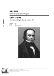
recognition (LPR) systems are generally composed of four main components; a light source to
illuminate the license plate, a video camera to capture images of passing vehicles, a computer
with image processing software, and a trigger that signals when a vehicle is passing.
7
Light Source
Video Camera
Laser Trigger
Computer
Fig. 1 General License Plate
Recognition System
8
III.A. LPR Light Source
There are several commercially available light sources on the market today that provide
the characteristics required by license plate recognition systems. A good example is the Extreme
UF500 infrared illuminator (specs are given in Appendix B). Some commercially available
products include both the light source and video camera in one single unit. A good example is
EagleVision’s Reg-L1 License Plate capture camera (specs are given in Appendix B). Light
source characteristics that are desirable for license plate recognition (LPR) are described in the
following paragraphs.
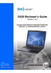
The light source should be physically located near the video camera. License plates are
coated with reflective paint. When a light source shines on an object coated with reflective paint,
the light rays are reflected back to the light source origin. This effect causes the license plate to
be significantly illuminated compared to other objects in the picture. An example of this effect is
shown in the figures below.
9
Fig. 2 Camera located near light source
Fig. 3 Camera located away from light source
Vehicle
Vehicle
Light Rays
Light Rays
Light
Source
Light Source
Video
Camera
Video
Camera
Fig. 4 Camera located near light source
Fig. 5 Camera located away from light source
The picture in figure 2 was taken with a light source and camera located near each other. The
light rays striking the license plate in figure 2 are depicted in figure 4. In figure 2, light rays
striking the license plate are mostly reflected back to the light source where the camera is also
located. This is what causes the license plate to be more illuminated than the rest of the objects in
the picture. The picture in figure 3 was taken with a light source and camera that were separated
by an angle of 45 degrees. Light rays striking the license plate in figure 3 are depicted in figure
5. Again, most light rays reflecting off of the vehicle license plate are reflected back to the light
source. However, in this case, since the video camera is no longer near the light source, the
license plate no longer appears more illuminated than the rest of the objects in the image. The
10
reflective paint effect greatly increases the luminescence of the license plate compared to other
objects in the picture when the angle between light source and camera aperture is reduced. A
highly luminescent license plate makes license plate detection based on contrast thresholds much
more accurate. (Contrast thresholding will be discussed later). The reflective paint effect is so
pronounced that it can cancel out the negative effects caused by unclean license plates.
Another desirable LPR characteristic is to project near infrared light (between 720nm1100nm). Near infrared light will not blind the vehicle driver because its wavelength is outside
the visible range. Also, light from other sources will not interfere with the light from the LPR
light source. As depicted in the diagram below, a filter placed in front of the video camera will
block all visible light and allow only near infrared light to pass through.
LPR Light
Source
LPR Video
Camera
Filter
Fig. 6 Visible light is blocked from the camera
Visible light is blocked because sources of visible light such as the sun, do not project
light in a uniform, constant manner. Character recognition software is less accurate when images
received from the camera contain lighting that is non-constant or non-uniform. Trees could block
light from the sun causing regions of the image to appear darker. Sun light intensity changes
11
according to the time of day or weather. Therefore, only the uniform, constant light provided by
an LPR light source should be allowed to enter the camera
Another desired LPR light source characteristic is to output light with high intensity. This
is due to several factors. For one, the license plate will be distant from the camera. More distant
objects reflect less light back to the camera. Two, the camera will use a fast exposure setting in
order to reduce image blur caused by the motion of the high speed vehicle. Three, the telephoto
lens used by the camera to magnify the image as well as the filter placed in front of the camera
will limit the amount of light received. And four, most CCD chips are not as sensitive to light in
the near infrared range requiring more light be received for the same image contrast. All of these
factors will cause the license plate image to appear dark and lessen its level of detail. However,
an LPR light source with very high intensity can offset these negative effects. The more light that
is emitted by a light source, the more light will be received by the camera. With more light, the
camera image will contain more detail, making image processing routines more accurate.
Another desirable LPR characteristic is to project a beam of light that illuminates the
entire width of the street lane. This will ensure that as long as a vehicle stays within its lane, its
license plate will be illuminated when it passes.
A summary of desirable LPR light source characteristics is given in the table below.
When a light source contains these characteristics, the intended license plate will be properly
illuminated.
Table 1 LPR Light Source Characteristics
Characteristic
Physical Location
Wavelength of light
Desired Value
As close as possible to camera
aperture.
Near infrared
12
Uniform and Constant
Intensity
Power of intensity
Projection Beam Angle
To be as uniform and constant as
possible.
To provide enough lighting so
that image detail meets image
processing requirements.
To cover entire width of street
lane.
III.B. LPR Camera
The second component of a license plate recognition system is the video camera. The
video camera captures images of passing vehicles and transfers those images to the computer. An
industrial or computer vision grade video camera provides the characteristics required by LPR
systems. A good example is the LXR CX800 (specifications are given in Appendix B). A video
camera for license plate recognition has three components; a long pass filter, a telephoto lens,
and a CCD chip. A description of these components and their characteristics is provided in the
following paragraphs.
Video Camera Components
License
Plate
Image
Digital
Signal
Light
Output
Input
CCD
Chip in
Camera
Telephoto
Lens
Long
Pass
Filter
Fig. 7 Video Camera System
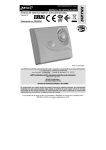
As depicted in figure above, light first passes through a long pass. This filter blocks light
in the short wavelength region (less than 720nm) and allows light with longer wavelengths (the
infrared region) to pass through. A graph of this effect is given below.
13
Fig. 8 Longpass filter properties (Ref 42)
All wavelengths of light smaller than the stopband filter are prevented from reaching the CCD
chip. All wavelengths of light larger than the passband limit are permitted to reach the CCD chip.
An optimal long pass filter would have a passband limit whose value is less than the wavelength
of light projected by the LPR system light source. For example, if an LPR system light source
projects 850nm wavelength light, the long pass filter should have a passband limit less than this
value. By blocking visible light, a long pass filter eliminates the negative effects of visible light.
After light is filtered by the filter it next passes through the telephoto lens. The telephoto
lens magnifies the image. Magnification is needed because vehicles will be imaged at a distance
and license plate characters will need to be magnified in order for object character recognition
software to function accurately. Vehicles are imaged at a distance for three reasons. One, the
camera angle, as depicted in figure 9, should be kept at a minimum. The larger the angle, the
more distorted the license plate characters will be due to 3D to 2D translation effects.
14
“Horizontal angle must not exceed 40 degrees (Ref 33)”. Two, the camera angle should also be
kept at a minimum to prevent motion blur. The larger the camera angle, the quicker a vehicle
will move across the camera’s field of view, causing a higher chance of motion blur. And three, a
larger time frame window will be given for capturing an image of a passing car if it is imaged at
a distance. This will prevent vehicles from passing the camera without having their image taken.
It should be noted that the distance between vehicle and camera not be so great that minimal
light from the license plate reaches the camera. A balance must be achieved to obtain optimum
picture quality.
Vehicle
Car
Distance
Front
Camera
Angle
Video
Camera
Fig. 9 Video camera orientation
Telephoto lenses have three relevant specifications; focal length, horizontal field of view,
and aperture. The focal length determines how much an image will be magnified. The higher the
value, the higher the magnification. A license plate under higher magnification will spread across
more pixels in an image which in turn increases character recognition accuracy. However, this
will decrease the horizontal field of view. The horizontal field of view (HFOV) specification
defines how much of a view is captured in a picture. The HFOV specification is given as an
angle and is depicted in the diagram below. The HFOV should be wide enough to capture an
image of a license plate of a passing vehicle that is traveling within its lane. For example, if a
15
lane is 9 feet wide, the HFOV should be at least 5 feet wide in order to capture the license plate
of a passing vehicle even when the vehicle is traveling within its lane.
Vehicle
2 Ft
2 Ft
Plate
1 Ft
5 Ft
HFOV
Video Camera
Fig. 10 Camera horizontal field of view
Another telephoto lens specification is the aperture. The telephoto lens aperture defines
the size of the hole that allows light to pass through. The larger the value, the more light enters
the camera providing faster exposure times. However, too large a value will provide a smaller
depth of field and the image will be in focus for only a small range. “The depth of field (DOF) of
a lens is its ability to maintain a desired amount of image quality as the object is positioned
closer to and further from best focus (Ref 41).” A telephoto lens that meets LPR requirements
will have a depth of field capable of imaging cars at varying distances and also allow enough
light to enter for fast exposure times.
16
The video camera has another component called the charge-coupled device (CCD) chip.
Light passes through the telephoto lens and lands on the video camera’s CCD. The CCD
converts electromagnetic energy received from the light into electrical energy. The CCD chip
sensors must be extremely sensitive to near infrared light. This is to offset the minimum amount
of light energy that will fall on the CCD as previously discussed. Sensitivity is usually defined in
a camera specification called the minimum illumination. It is measured in LUX. The lower the
LUX value the more sensitive the camera is to light. A very low LUX value is desirable for
license plate recognition. Consumer cameras are built to be sensitive to mostly visible light. An
LPR camera needs to be sensitive to near infrared light. The graphs below show the difference in
sensitivity between a standard consumer CCD chip and one specialized for infrared imaging.
17
Sensitivity (%)
100
80
60
40
20
400
500
600
700
800
900
1000
Wavelength (nm)
Fig. 11 Sensitivity for standard consumer CCD (Ref 43)
Sensitivity (%)
100
80
60
40
20
400
500
600
700
800
900
1000
Wavelength (nm)
Fig. 12 Sensitivity for LPR CCD
An LPR CCD is much more sensitive than a standard consumer CCD chip at the near infrared
wavelengths of light (>700nm). Such sensitivity is necessary to capture detailed images of high
speed moving objects at a distance with near infrared illumination.
Another CCD specification is the large number of image pixels needed to accurately
recognize license plate characters. If the camera’s field of view covers most of the lane’s width,
the license plate will extend only a small portion across the image minimizing the number of
pixels each license plate character spreads across. It is desirable for a license plate character to
cover a certain number of pixels in order to be accurately recognized. For example, if a camera’s
HFOV is 5 feet across and its horizontal image size is 640 pixels, then the character “1” whose
18
width is only 5/16” will be 3 pixels wide ((5/16)/(5*12)*640 pixels). This may or may not be
enough pixels depending on the object character recognition algorithms being used. On the other
hand, having too many pixels can cause a negative effect. The more pixels an image contains, the
longer it will take image processing routines to process the image. A balance must be met.
It should also be noted that camera images should be clear and sharp with little noise.
Cameras that output digital signals such as DTV or computer protocol signals such as IEEE 1394
generally have better image quality than cameras that output analog signals such NTSC or PAL.
It is desirable for an LPR customized camera to output a clear, sharp image to increase the
accuracy of software image processing and character recognition routines.
Also, depending on how the video camera is implemented, it should either have a trigger
port or a very high frame rate. The trigger port is used to signal the camera when to take a
picture. The camera trigger port is connected to the trigger component of the LPR system that
senses when a car is present. If the same video camera is also being used as the trigger
component then it should have a very fast frame rate. This will ensure an image of the vehicle is
captured before passing the camera.
A summary of desirable LPR video camera characteristics is given in the table below.
When a video camera contains these characteristics, a high quality image of the intended license
plate will be captured.
Table 2 LPR Video Camera Characteristics
Characteristic
Long pass filter
Telephoto Lens
Magnification
Telephoto Lens Field of
View
Desired Value
All visible wavelengths of light are
blocked.
Powerful enough to image license
plate characters at a distance
Wide enough to capture license plate
when vehicle travels within its lane
19
Telephoto Lens Aperture
Small enough to provide required
depth of field, but large enough for fast
exposure time
CCD Sensitivity / Minimum High sensitivity. Low LUX value for
Illumination
infrared lighting
Signal Output
Digital or computer protocol for clean
high resolution image
Frame Rate (optional)
If camera is also being used as a
trigger it must have a high frame rate
Trigger Port (optional)
Most cameras have a trigger port that
is used to signal the camera when to
take a picture
CCD Resolution
High enough to provide acceptable
level of license plate detail when
capturing an entire lane width
III.C. LPR Computer
A computer specialized for license plate recognition is similar to a standard PC running a
Windows or Linux operating system. An example of a good candidate computer would consist
of an MSI Industrial GM965 Mini-ITX motherboard running an Intel Core 2 Duo Mobile
processor (see appendix B). There are several characteristics an LPR customized computer
should have. A powerful microprocessor and much memory are needed to perform the
demanding calculations needed by the image processing and object character recognition
algorithms. Having multiple processors is a plus due to the parallel nature of these algorithms.
For example, one processor can run low level image processing functions while another
processor performs object character recognition functions. For roadside LPR systems, it is
desirable to have computers that are compact, weather proof, and consume minimum electricity.
They may need to have wireless communication if wired technology is unavailable. The LPR
computer may also need to have an image acquisition capture card in order to connect to a
camera. The type of card is dependent on the camera interface. If camera output is an analog
20
signal, such as NTSC, a capture card with composite input is needed. If the camera output is a
computer standard, such as the IEEE1394 protocol, a FireWire card may be necessary. It is
important to note that different types of cards require different software drivers and the license
plate recognition software must be able to communicate with the appropriate driver. Other than
these specifications an LPR customized computer is much like any other desktop PC.
Table 3 LPR Computer Specifications
Characteristic
Camera Interface
Computer Case
Power Consumption
Processing Power
Wireless capability
Capture Card Driver
Desired Value
Must match camera output or have PC card
that can connect to camera
Weather proof
Minimum power input
Comparable to high end desktop machine. The
more processors the better.
Needed if wired technology is unavailable
Must be compatible with image processing
software
III.D. LPR Trigger
The fourth component of an LPR system is a trigger. License plate recognition systems
need triggers to detect the presence of a vehicle and to signal the system to start capturing images
of passing vehicles. There are many different types of triggers. An example of a trigger is MDL’s
LaserAce® IM OEM Laser Modules (specifications given in Appendix B). MDL’s LaserAce
modules are laser range finders that detect the presence of a car using laser technology. A trigger
is composed of some type of sensor that senses the presence of a passing vehicle and outputs an
electrical signal when a vehicle is detected. This signal is sent to a camera’s “external trigger”
port. The camera starts to capture images when this signal is received. Most triggers are not
21
specifically sold fold for license plate recognition and must be customized to be incorporated in
to the LPR system.
Other types of triggers include pressure sensors, infrared sensors, magnetic field detector
sensors, and video cameras. Pressure sensors consist of tubes or wires that are laid across the
roadway. When a vehicle rolls over the tube or wire, the pressure in the tube rises or the
resistance in the wire changes, causing the sensor to output an electrical pulse. Infrared sensors
use infrared light to detect the presence of a vehicle. It is similar to the sensors located on an
automatic garage door opener that prevent the door from closing when an object is located under
the door. The infrared sensor consists of an emitter and receiver. The emitter sends infrared light
to the receiver. If the receiver does not receive the infrared light it sends an electrical pulse,
signaling an object is in its path. A magnetic field detector sensor detects the presence of vehicle
by the vehicle’s magnetic field. All vehicles have a magnetic field due to the large amount of
metal used by them. Video cameras can also act as triggers. They can continually monitor the
street and use image processing techniques to detect the presence of a moving object. For traffic
violation type applications, laser range finders are mostly used to trigger the camera.
There are certain specifications that are desirable for an LPR customized trigger. It is
desirable to have a sensor that is unobtrusive as possible. If tubes or wires cannot be laid across
the road, then pressure sensors cannot be used. It is also desirable to have a sensor with a very
quick response time. Magnetic sensors may not have a quick enough response time for fast
moving traffic, triggering the camera at wrong intervals. It is desirable to have a trigger that can
be located near the camera. This will eliminate the need for costly extra support structures and
long cable runs between camera and trigger. Some laser range finders require they be placed
directly over roadways, requiring extra structures to support the system. It is also desirable to
22
choose a trigger that will require the least amount of work to be incorporated into an LPR
system. Video cameras will require a computer and special software. Care must be taken to
choose the appropriate trigger for the application at hand.
Table 4 LPR Trigger Specifications
Characteristic
Location
Response time
Obtrusiveness
Work required to incorporate
trigger in to system
Desired Value
Near camera
Extremely quick for fast
moving traffic
As unobtrusive as possible
Minimal
23
IV. Speed Detection Radar Concepts
At the start of this project we discussed various methods for determining the speed of a motor
vehicle, including speed trailers (fig. 13), hand held radar units (fig. 14), laser rangefinders,
traffic classifiers, traffic counters with road tubes, ultrasonic detectors, Passive Infra-red (PIR)
detectors, and microwave radar units.
Fig. 13 Speed Trailer
Fig. 14 Hand-held Radar
The purpose was to have these units act as a sensor to start the camera operation and trigger
the license plate recognition software. From our initial research, we concluded that commercially
available speed trailers and professional quality police radar units were far too expensive for this
project. Speed trailers cost around $5,000 and police radar units’ cost around $800. Since the
ultimate goal of this pilot project was to combine speed detection, license plate recognition, and
wireless mesh networks into a viable system, we felt that the financial support we had could be
better utilized in other areas.
24
We briefly considered laser rangefinders, but decided they were too dangerous and
costly, even if we could obtain ones that were used by law enforcement. A special class of laser
is required for police laser radar detectors, which adds to their cost. The laser rangefinders used
for measuring distance on a golf course, for example, are not manufactured in a way that allows
them to be pointed at people. Thus, they would be extremely dangerous if used to measure
vehicle speeds. We would also have the problem of measuring the speed of an object since these
units are for distance only.
The traffic classifier units and traffic counters with road tubes, while less expensive than
the speed trailers and police radar units, have the major drawback of needing to place a portion
of the unit in the roadway. We felt that this would require special permission from the various
regulatory agencies (State Department of Transportation, State Traffic Commission, City of New
Britain, etc.) which may have taken a long time to be granted, if at all.
Both the PIR motion detectors and the ultrasonic rangefinder, while inexpensive,
have problems with the wide detection field and short effective distance. The camera system we
decided to use provides a quality image at distances from 50 to 500 feet, depending on which
camera lens is installed. Although the PIR detector could cover the shorter end of this range, it
would respond to any motion within a 60-degree field of view. The ultrasonic detector suffered
from an extremely short usable range, which did not exceed 10 feet.
This leaves us with the microwave radar units, of which we found two very inexpensive
types. Mattel Toys makes one for their Hot Wheels 1/64 in. scale cars (fig. 15), and the other one
is a kit made by Ramsey Electronics (fig. 16).
25
Fig. 15 Hot Wheels Radar Gun
Fig. 16 Ramsey Electronics Radar Kit
Since the Mattel Radar Gun was the least expensive, we purchased that one first. Both of these
units operate in the microwave range of frequencies. The Mattel unit at 10.525 Gigahertz (GHz)
is an X-band radar unit; the Ramsey kit at 2.6 GHz is in the now obsolete S-band (Ref. 10). Both
units determine the speed of an object based on the Doppler Effect.
26
Fig. 17 Doppler Effect (Ref. 14)
The Austrian physicist Christian Andreas Doppler first described the Doppler Effect in
1842. He noticed how the frequency of a sound wave changed as the emitting object moved
toward or away from a stationary listener. When the emitting object was coming toward the
listener, the pitch or frequency of the sound increased. But as the object moved away from the
listener, the pitch decreased. The largest Doppler Effect is heard when the source is moving
directly toward or away from the listener. The frequency heard by the listener can be calculated
from the following equation:
fL = [(v + vL)/(v + vS)] fS
(Eq. 1)
where: fL is the frequency heard by the listener
fS is the frequency emitted by the source
Different sources have differing names for Dr. Doppler. On a NASA website, he is Johann Christian Doppler.
Webster’s Dictionary has him simply as C.J. Doppler. Wikipedia gives his name as Christian Andreas Doppler
27
v is the speed of sound (In dry air with a temperature of 21 °C (70 °F) the speed
of sound is 344 m/s (1230 km/h, or 770 mph, or 1130 ft/s).
vL is the velocity of the listener
vS is the velocity of the source
If both the listener and the source are stationary, then vL and vS =0 and fL = fS. The sound heard
by the listener is the same as that emitted by the source. If the source is moving toward the
listener, then vS is negative (by convention, in an inertial reference frame) and the quotient in
Eq. 1 becomes larger; the pitch heard by the listener increases. However, if the source is moving
away from the listener, then vS is positive (by convention) and the quotient of Eq. 1 gets smaller;
the pitch heard by the listener decreases. Conversely, if the listener is moving toward the source
of the sound, vL is positive (by convention); the quotient in Eq. 1 becomes larger and the pitch
increases. If the listener is moving away from the sound then vL is negative; the quotient in Eq.1
becomes smaller, and the pitch decreases.
In general, police Doppler radar systems are set up in the manner shown below:
28
In this project, we will be using the conventional police method of pointing the camera and radar
gun down the road. As you can see from the diagram, police radar can detect vehicle speeds
when the vehicle is up to a mile away. The radar units we used in this project have a range from
100 ft. to ⅛ mile.
Problems with the Mattel Speed gun
When the Mattel Toy’s speed gun was taken out of it’s housing (fig. 19, Ref. 5); we
discovered the following problems:
Fig. 19 Inside of Mattel Radar Gun
Fig. 20 Radar Gun Circuit Board
1. The circuit board was a double layered board (fig. 20, Ref. 5)
2. The circuit contained an embedded ATmega88 microcomputer
3. The source code on the microprocessor was locked
4. The locks could be removed only by erasing the entire code
5. Even though the ATmega88 has UART pins, we doubted the code was written to address
them.
6. A search of the Internet revealed only one partial circuit diagram which was of little help.
29
7. The source codes and circuit diagrams are proprietary property of Mattel Toys, and they
would not release them even for a discontinued toy.
Given these drawbacks, the only part of the Mattel Speed Gun that might prove useful would be
the detector tube with it’s transmit and receive antennas; all other supporting circuitry would
have to be designed from scratch. We felt we had another alternative in the Ramsey Electronics
SG7 kit, which will be described later.
30
V. Our System Design and Implementation
V.A. Overview
The system designed and implemented for this project is called the license plate
recognition / speed detection (LPR/SD) system. The system receives two inputs. One input
consists of live video taken of passing vehicles traveling down a throughway. The second input
is the speed of passing cars obtained from a radar gun. The LPR/SD system processes these
inputs, and outputs a computer file. The file contains information on passing cars including their
license plate number, the speed they were traveling, and the time and date they passed.
Output
Inputs
Live Video
Computer file
containing vehicle
information
License Plate
Recognition /
Speed Detection
System
License Date
FTY424 4/24/07
RST256 4/24/07
TRS842 4/24/07
SLG874 4/24/07
Radar Gun
Time
8:30A
8:29A
8:28A
8:22A
Spd
54
46
48
45
Fig. 21 LPR/SD system inputs and outputs
Our LPR/SD system is physically placed on the side of a throughway. It continuously
monitors passing traffic. The system is composed of five main components as depicted in the
31
figure below; a light source, video camera, computer, serial interface circuit board, and radar
gun.
Light Source
License Plate Recognition /
Speed Violation System
Video Camera
Computer
Serial Interface
Circuit Board
Radar Gun
Fig. 22 LPR/SD system components
The light source illuminates the license plate of a passing vehicle. The video camera captures
images of the front of the vehicle as the vehicle passes and sends those images to a computer.
The radar gun detects the speed of the vehicle and sends speed information to the serial interface
circuit board (SICB). The SICB provides a means of passing the speed information to the serial
port of the computer. The computer processes images received from the camera and detects the
license plate characters from the images. The computer also receives speed information sent by
the SICB. The vehicle license plate number and speed are recorded in a file on the computer.
Our LPR/SD system process flow is depicted in the figure below.
32
LPR/SD System Process Flow
Retrieve picture of
throughway
NO
Does license
plate exist in
image?
YES
Get vehicle speed
Detect license plate characters
Record time, vehicle speed, and
vehicle license plate numbers
Fig. 23 LPR/SD system process flow
33
V.B. License Plate Recognition / Speed Detection System
Components
V.B.1. LPR Components
The license plate recognition part of our system includes the light source, video camera,
and computer components. Our budget limited us to the most basic appliances. We used a
vehicle’s headlights for a light source, a FireWire webcam for a video camera, and a laptop for a
computer. (We also tried using just sun light for a light source). Pictures of our system setup are
given below. The system was setup two different ways. One way was to position the system in
front of a vehicle and use the vehicle’s headlights for a light source. This is shown in figure 24.
Another way our system was setup was to position the system on top of a small desk and use
only the sun as a light source as shown in figure 25.
Fig. 24 Image of our LPR/SD system in front of a vehicle
34
Fig. 25 Image of our LPR/SD system positioned on desk using sun as light source
One major difference between our system and a commercial license plate recognition
system is our use of visible light to illuminate the license plate. Most LPR systems use nearinfrared light. It should be noted that both types of light produce the same effects when shown on
reflective paint. The reflective paint on the license plate causes the license plate to be highly lit
when illuminated by a light source that is placed near the camera aperture. This holds true
whether the light source is emitting visible light or infrared light. It will make it easier for the
image processing algorithms to extract the license plate characters from the image. However,
using visible light for a light source is impractical. Shining bright visible light at passing vehicles
35
is dangerous and may temporarily blind the driver of a car. Also, light from external light sources
will interfere with the light coming from our light source. Light from the sun or another vehicle’s
headlights can interfere with our light source light, lowering the accuracy of the image
processing algorithms. Using visible light also changes the requirements on our system video
camera. As previously discussed, most LPR cameras are sensitive to near infrared light and block
all other wavelengths of light. Since our system is using visible light to illuminate the license
plate, our camera must also be sensitive to visible light.
For our system video camera, we used a UniBrain FireWire webcam. Complete
specifications are given in appendix A. We chose this camera for several reasons. The camera
only cost $105 and was within our budget constraints. It was also able to retrieve images at 30
frames per second. We needed the high frame rate in order to capture images of passing vehicles
before they drove out of the camera’s view. The camera output images in digital format at
640x480 pixels. Therefore pictures were clean with little noise and the high resolution provided
the needed detail to recognize license plate characters. A 50 mm focal length lens was mounted
on the camera providing the magnification needed to image vehicles at a distance. One major
advantage of using this camera was that it used the IIDC DCAM (Instrumentation & Industrial
Digital Camera protocol). “Most FireWire webcams available are compliant with the IIDC
specification. This means that no device-specific driver is necessary to interface with the camera
(Ref 34)”. I was able to find a free software library for this protocol and used it to communicate
with the webcam. One major disadvantage of using this camera was the long exposure time
needed to capture images using a telephoto lens. The long exposure time limited the speed
vehicles could travel without causing any blur.
36
Our video camera served two functions. One, it had to capture high quality images of
passing license plates for the recognition software to extract and recognize license plate
characters, and two, it was used as a trigger to detect the presence of a license plate in an image.
We had to make sure the camera was capable of performing both functions. We also needed to
know how to setup the camera to perform both functions. To answer these questions we would
have to solve for the three distances shown in green in figure 26.
Fig. 26 Three distances to calculate for camera setup
Distance 1, the “Camera to Vehicle Distance” would tell us where to focus the camera on
the street lane. This distance was found to be 40.88 feet. Distance 2, the “Maximum Vehicle
Travel Distance” is the maximum distance a vehicle could travel within our camera’s field of
view. This distance was found to be 6.69 feet. From this distance we deduced that once a
vehicle’s speed reached over 136.84 mph, it may be possible for the vehicle to pass the camera
undetected. Distance 3, the “Camera Field of View Distance”, is the amount of distance covered
by the camera’s field of view. This distance was found to be 51.42 inches. From the “Camera
Field of View Distance” we deduced that a vehicle could veer up to 19.71” inches from the
center of its lane and still be sensed by the camera. From these calculations we predicted that our
37
camera would be capable of performing both functions. It would be possible to both, capture
high quality images of license plates for character recognition, and also, be used as a trigger to
signal when an image should be passed to the character recognition routines. Calculations for the
distances shown in figure 26 are given in appendix C.
Our LPR system used a standard laptop (Compaq nc6220) to run the image processing
and object character recognition software. The processing power of the laptop was fast enough to
detect the presence of a vehicle in an image within the 30 frames per second time limit. It was
also fast enough to perform the character recognition before a second vehicle would pass. We
also purchased a FireWire PCMCIA card for the laptop to be able to connect the video camera to
the laptop since it did not have a FireWire port. Using a laptop is impractical for an LPR system.
Most systems need to be weatherproofed.
.
38
V.B.2. Radar Gun
The Ramsey Kit
Ramsey Electronics of Victor, New York (Ref. 3) has been selling hobby electronic kits
since the early 1970’s. The advantages of using the Ramsey kit over hacking the Mattel toy is
that the kit has a full schematic diagram and all parts are labeled. Thus it is easier to locate the
point in the Ramsey circuit where we could tap into the circuit for an RS232 fed line. We
purchased and assembled a kit similar to the one shown below.
Fig. 29 Ramsey Radar Gun Kit
The Microwave Oscillator Circuitry
The kit contains two printed circuit boards that require assembly, the microwave
oscillator board and the speed readout board. . We will discuss each in turn. Figure 30 is the
circuit diagram for the microwave oscillator. Figure 31 shows the completed circuit board.
39
Please note, for reader convenience, we have included data sheets for all transistors, diodes, and
integrated circuits (IC) on the CD-ROM attached to this report.
Fig. 30 Microwave Oscillator Circuit Diagram
40
Fig. 31 Assembled Oscillator
The microwave oscillator circuit performs two functions. First, it produces a 2.6 GHz
signal which is broadcast via a quarter-wave dipole patch antenna. Second, it uses a quarter wave
antenna mounted in a resonant cavity to receive the reflected signal from the object whose speed
we want to measure. Two one pound coffee cans (with the ends cut out of one of them) are
soldered together to form the resonant cavity. A stiff piece of wire is cut so that it extends
approximately 1.1 inches into the can. It is mounted 1⅞ inches from the closed end of the can.
This forms a ¼ wave dipole antenna housed in a resonant cavity. The metal walls of the coffee
cans reflect the incoming radiation in a way that allows only those signals with wavelengths that
are multiples of the can diameter to undergo constructive reinforcement. This concentrates and
intensifies the radiation prior to entering the detector circuitry. The resonant cavity also helps
narrow the angle from which the antenna can receive a signal, which improves the pointing
41
direction. We expect the beam width to be in the range of 15 to 20 degrees, although we haven’t
measured it.
The oscillating electromagnetic wave induces an alternating current in the antenna wire.
This current forms the signal we are trying to detect. The signal is passed to a Schottky diode
(a.k.a. hot carrier diode). These diodes have low junction capacitance, low junction voltage, and
fast switching speeds; making them ideal for the detection of low voltage high frequency signals.
The signal then passes through a low pass filter circuit. This circuit is formed by the R3 1kohm
resister and the surface mounted 0.001 micro Farad capacitor C7. A low pass filter is used when
we are interested in frequencies below a specified (cutoff) level. The following equation is used
to calculate the cutoff frequency:
Fc =
____1_____
2**R*C
Where: Fc = the cutoff frequency
= 3.1415
R = resistance in Ohms
C = capacitance in Farads
For this section of the circuit the cutoff frequency is 159.2 kHz. The Ramsey user’s manual
states “the correct Doppler shift at the operating frequency is 7.76 Hz per mile-an-hour (Ref 1).”
Since the readout provides for a two-digit display, we can measure speeds up to 99 mph. This
gives a Doppler shift of approximately 770 Hz.
The filtered signal now passes to the base of a NPN 2N3904 transistor that is configured as a
common emitter amplifier. The 2N3904 is a general-purpose transistor that can amplify a signal
42
up to 100MHz. Once the signal has been amplified, it is capacitively coupled to the signal
output jack (J1) and sent to the readout circuit.
The NE021 transistor, the patch antenna and a few passive components form the
remaining part of the circuit. The NE021 transistor is configured as an oscillator and it produces
the 2.6 GHz signal. This signal is passed to the foil patch antenna mounted directly on the
printed circuit board. The signal is coupled to the waveguide and forms the initial radar beam.
The Readout Circuit
Figure 32 shows the completed readout circuit board. Figure 33 shows the speed readout circuit
diagram.
Fig. 32 Assembled Readout Board
43
Fig. 33 Readout Circuit Diagram
44
I will discuss the pathway the input signal takes through the readout circuit from the input jack to
the 7-segment LED display. For brevity, I will ignore the headphone, calibration, and gain
control circuitry.
Two six-volt dry cell lantern batteries connected in series powers the readout display. The
input power is separated by a voltage divider circuit (formed by resisters R1 and R2), to give a
12 volt supply and a 6 volt supply needed by the integrated circuit (IC) chips.
The signal from the microwave oscillator enters the readout circuit via the signal jack, J1.
The signal is amplified by passing through all four stages of an LM324 Quad Op-Amp. The
input signal is applied to the non-inverting pin of each amplifier stage and negative feedback
loops are used to control the gain and prevent the op-amp from going into saturation. The gain
(G) in a negative feedback loop is controlled by the values of the resistors in the voltage divider
configuration in the specific loop. The gain (G) = 1 + R2/R1.
The amplified signal leaves the last stage of the LM324 Op-amp at pin 7 and is directed
to the input pin of a 4093 Quad Schmitt trigger NAND IC. A Schmitt trigger has the unique
ability to convert any type of input waveform into a square wave output and at the same time
acting as a noise filter. The graph below (figure 34) shows an arbitrary waveform at the top of
the graph and the resulting output after passing through a Schmitt trigger. The Schmitt trigger is
a type of comparator IC that uses two independently set thresholds. When the input waveform is
below the lower threshold, the Schmitt trigger’s output is low. When the input waveform is
above an upper threshold, the Schmitt trigger’s output goes high. The Schmitt trigger’s output
changes only at those times when the input waveform’s trailing edge crosses the upper threshold
45
limits; or when it’s leading edge crosses the lower threshold. The Schmitt trigger IC effectively
converts the input signal to a digital signal, i.e. highs = 1, lows = 0.
Fig. 34 Schmitt Trigger Operation
A comparator IC uses only one adjustable threshold level. It’s output changes each time
the input waveform crosses the threshold. See graph below (figure 35). Given the same input
waveform, these graphs show the comparator IC to be prone to noise interference. A noisy input
signal close to a comparator’s threshold level, may cause the comparator to turn on and off
unnecessarily.
46
Fig. 35 Comparator Operation
The signal from the Schmitt trigger is fed into a NAND gate, which incorporates the
signal from the calibration circuit. The signal then goes to the enable pin of a dual Binary Coded
Decimal (BCD) decade counter. The counter drives two separate LED readouts, the tens place
and the ones place. When the ones value reaches 9, the counter rolls over and places a high value
on the enable pin of the second half of the counter. This half operates the tens place value on the
LED display. Combined, these two LEDs form the visual display of the vehicle’s speed. This
completes the brief description of the circuits in the radar gun.
The unit, according to Ramsey Electronic, is capable of measuring speeds up to and
above 99 mph. We did not test the accuracy of this claim. The User’s Manual suggests one way
of testing the radar gun at higher speeds is to point it at aircraft on landing approach. Since the
September 11th 2001, attack on the World Trade Center and the tightened airport security that
47
resulted, we felt it would be asking for trouble to follow this suggestion. Thus we decided to
accept the limitation of a two-digit display.
We came across some Blogs on the web during the course of our investigations
concerning the size of an object that can be detected by the radar gun. To detect an object, its
physical size must be equal to or greater than the wavelength of the impinging radiation. The
Ramsey radar gun operates at a frequency of 2.6 GHz. So an object larger than the corresponding
wavelength will be detected, while smaller objects will go unseen.
Use the following formula to calculate the wavelength (λ) corresponding to a frequency of 2.6
GHz:
λ = c/f
where: λ = wavelength
c = speed of light, 186,000 miles per second
f = frequency in Hertz (Hz)
Thus:
λ = 186,000 miles/second ÷ 2,600,000,000 cycles/second
= 0. 00007154 miles x 5280 ft/ mile
= 0.3777 ft x 12 in/ ft
= 4.53 in
At a frequency of 2.6 GHz the smallest object that can be detected is 4.53 inches in diameter.
48
V.B.3. Serial Interface Circuit Board
The optical character recognition system stores the processed images on a laptop
computer. We wanted to store the speed data from the Ramsey Radar Gun on the same computer.
The Radar Gun kit was not designed to provide a computer interface, so we decided to solder an
eight wire ribbon cable to the output pins of the dual BCD decade counter IC chip. The ribbon
cable could then be brought to the outside of the Ramsey Readout case. This entailed drilling two
one-sixteenth inch holes into the top of the case with the holes spaced far enough apart to allow
the ribbon cable to slip smoothly between them. The plastic between the two holes was carefully
filed away until the two halves of the case would close without binding or cutting into the ribbon
cable. An eight pin breakaway header was soldered to the opposite end of the cable.
The laptop computer has a serial port available for communication with peripheral
devices. To convert from the parallel output on the ribbon to a serial input needed by the
computer, we used a module from Parallax, Inc (figure 36).
Fig. 36 Parallax HomeWork Board
This unit is from a Parallax training kit for embedded microcontrollers. It contains a
programmable PIC microcontroller (μcontroller), a MAX232 chip, and a serial port. The Max232
49
chip handles the RS232 communication requirements. The ribbon cable from the radar gun plugs
into the black sockets marked P15 to P8 on the left side of the white breadboard.
The PIC μcontroller requires a program in order to function. The BasicStamp2™ modules are
programmed with Pbasic (Parallax Basic) v. 2.5 that is supplied in the HomeWork training kit.
The programming is done on a computer running the BasicStamp2 Editor™ software and is then
downloaded to the PIC μcontroller on the HomeWork board. Once the PIC is programmed it will
continue to run its program ad infinitum. To stop the program, just unplug the battery; to start it
again just plug the battery back in. The program we used to acquire data from the Ramsey Radar
Gun is shown below:
'Speed Gun Sensor
‘Uses a Ramsey Electronics SG7 Personal Radar Speed Gun kit as a speed sensor
' {$STAMP BS2}
‘{$PBASIC 2.5}
Main:
INPUT 15
INPUT 14
INPUT 13
INPUT 12
INPUT 11
INPUT 10
INPUT 9
INPUT 8
PAUSE 200
‘Sets pins as input pins
‘Pauses program for 200 milliseconds
DEBUG BIN1 IN15, BIN1 IN14, BIN1 IN13, BIN1 IN12, BIN1 IN11, BIN1 IN10,
BIN1 IN9, BIN1 IN8, CR ‘Reads the value on each pin and sends it to the laptop
GOTO Main
END
‘Loops endlessly
The Speed Gun Sensor program runs a BasicStamp2™ module ({$STAMP BS2}), using the
PBasic v. 2.5 programming language ({$PBASIC 2.5}). In the “Main” section of the program,
50
we set pins 8 to 15 as input pins and pause the program for 200 milliseconds. This pause time
was chosen because it is somewhat longer than the cycling time of the BCD counter, which
requires ~143 milliseconds to update itself. After pausing, the DEBUG routine sends the value
on each input pin out the serial port to the laptop via an RS232 connection. The value on pin 15
represents the most significant bit and the value on pin 8 represents the least significant bit in the
Binary Coded Decimal. The laptop computer takes this binary input and converts it back to the
decimal value of the vehicle’s speed.
When the Ramsey kit was assembled, we used IC sockets to mount the IC chips instead
of soldering them directly to the printed circuit board. This allowed us to solder the ribbon cable
to the BCD counter chip without having to worry about damaging the chip (or any other chip
during assembly). In testing the Radar Gun – BasicStamp combination, it was noticed that the
digital readout on the Radar Gun went blank, which meant we did not have an independent
confirmation of the vehicle’s speed. The problem appeared to be caused by too large a drain at
the BasicStamp connection. To remedy the problem, we first unsoldered the ribbon cable from
the Readout’s BCD output pins. Then we purchased a second dual BCD decade counter and
mounted it on the HomeWork module’s breadboard. Next, the input signal was taken from the
Readout’s Quad NAND gate IC chip at pin 11. The second BCD counter was wired on the
breadboard exactly as the one on the Readout’s circuit board, except it draws power directly
from the lantern batteries and the second BCD’s output pins were now connected to the
HomeWork board’s input pins.
51
V. B.4 Table of License Plate Recognition / Speed Detection System Hardware
Components
Table 5 Our LPR/SD Hardware Components
Component Description
Store Bought From
Unibrain Fire-I Board Color
www.unibrain.com
Video Camera
12V AC adapter
www.unibrain.com
Unibrain FirWire 400 CardBus www.unibrain.com
Card
Unibrain 50mm Telephoto Lens www.unibrain.com
Ramsey Electronics SG7 kit
www.ramseyelectronics.com
(Radar Kit)
Basic Stamp Training Kit
www.parallax.com
(Serial Interface Circuit Board)
Compaq nc6220 (Laptop
www.hp.com
Computer)
TOTAL:
*Note: We did not include the cost of the laptop computer.
Purchase Price
105$
$20
45$
$70
$70
$80
*
$390
V.C. LPR Software
There are software packages available for license plate recognition. An example is HITECH Solutions SeeCar Software Recognition Package (pricelist given in Appendix B).
However, these software packages cost over $4,000 per license which was beyond our budget
limits. Instead, we wrote our own software to perform the license plate recognition. We
researched free available software libraries to minimize the amount of customized code that
would need to be written. Customized code was written to glue these libraries together and
provide any additional functionality. The libraries and customized code were combined in to one
application executable called LPR.exe. The executable runs on Microsoft Windows XP. The
following screen shots show the menus and windows of the application.
52
Application Main Window
Fig. 37 LPR.exe application main window
The picture above shows the main window of the application. There is a main menu on
top and live video from the video camera is shown beneath. The main menu contains several
items that each open a sub menu. The “Camera” main menu item opens a submenu containing
commands to initialize the camera. These include commands to adjust camera settings such as
brightness, exposure time, sharpness, white balance, hue, and saturation. The “Mode” main menu
item opens a submenu to set the image type. Image types define the image format type, i.e. YUV,
RGB, Mono as well as image size, 640x480, 320x240, or 160x120. The “Rate” main menu item
53
opens a submenu that sets the camera’s frame rate, i.e. 30fps, 15fps, 7.5fps, etc. The “LPR” main
menu item contains commands to set the intensity threshold and also commands to start and stop
recording plate numbers to a file. There are two other application windows in addition to the
main window. They are the “Processed Image” window and the “License Plate Detected”
window. They are shown below.
Processed Image Window
License Plate Detected Window
Fig. 38 Processed image
Fig. 39 License number detected
The “Processed Image” window shows live video from the webcam that has gone through image
processing. Image processing functions create a black and white image where pixel values are
either black (0) or white (1). The “License Plate Detected” shows the last license plate number
detected and the speed the vehicle was traveling. The license plate number shown in this window
is not an image but text. The three application windows show how the software converts live
video to license plate number data.
54
Fig. 40 LPR.exe application windows showing image progression
V.C.1 Instructions for Running the Application
The application is run by double clicking the LPR.exe icon on the desktop. Before the
application can successfully record license plate numbers of passing vehicles, the intensity
threshold must first be set. The intensity threshold is a value used by the image processing
algorithms and will be described in more detail later. To set the intensity threshold, the video
camera should be placed in its final position along the roadside. The camera should be focused
on a vehicle license plate. The vehicle should be in the center of its lane approximately 38.5’
from the camera lens.
1.
2.
3.
4.
Click Camera->check link. This will search the laptop for attached cameras.
Click Camera->select camera. This will select the desired camera.
Click Camera->init camera. This will initialize the camera.
Click Mode->640x480 Mono (8 bit). Camera images will be 640x480 pixels, each pixel
will have an 8 bit value.
5. Click Camera->Show Camera.
6. Click Camera->Control Dialog (Optional). Set appropriate camera settings for a clear
readable image picture or leave on auto settings.
7. Click Rate->30fps. Sets camera to send images at 30 frames per second.
8. Click LPR->Set Threshold plate number. Enter the license plate number of the vehicle in
focus.
9. Click LPR->Set Intensity Threshold. This will set the intensity threshold.
10. A popup window will show the chosen intensity threshold. Make sure this number is not
0 and click OK.
Once the threshold is set, the application can start recording license plates of passing vehicles.
Click LPR->Start Recording to record license plate numbers to a file named licensePlates.txt.
55
V.C.2. Software Architecture
To create the application, we researched available software libraries that were within our
budget limits. We then created customized C/C++ code to glue these libraries together as well as
add any additional functionality. We used Microsoft Visual C++ to compile and link the
application. A diagram of the software layer architecture is given below.
LPR Application
Microsoft MFC Intel OpenCV Serial Library Tesseract IIDC DCAM
Intel IPP
Fig. 41 Application software layer architecture
The LPR application layer contains the customized code we created for the application. It
calls functions contained in the lower layer libraries. The Microsoft MFC library was used to
help create the user interface. It contains C++ classes for creating application windows and
menus. This library is not free and comes with certain versions of the Microsoft Visual Studio
package. The Intel OpenCV (Open Computer Vision) library provided computer vision functions
to process live video images being received from the webcam. Its functions provided the
capability to segment license plate characters in to separate images. This library is free and can
be downloaded from www.sourceforge.net. The Intel OpenCV library can be configured to use
the Intel IPP (Integrated Performance Primitives) library. This library provides low level image
processing functions that are optimized for Intel processors. A student edition of the Intel IPP
library can be purchased for $25. The Serial library provides functions for communicating with a
computer’s serial port. This library was used to retrieve data being sent by the radar gun. The
56
Serial library was written by Ramon de Klein and was downloaded for free from
www.codeguru.com. The Tesseract library provided the functions for object character
recognition. This library converted images of characters in to actual text. This library can be
downloaded for free from http://code.google.com/p/tesseract-ocr/. The IIDC DCAM library
provides communication to the FireWire video camera. The library was developed at the
Robotics Institute of Carnegie Mellon University. It can be downloaded for free from
http://www-2.cs.cmu.edu/~iwan/1394/. The library uses the IIDC DCAM protocol otherwise
known as the Instrumentation & Industrial Digital Camera protocol to communicate with the
camera.
V.C.3 Application Layer Algorithms
Much work was done at the application layer to provide the additional functionality and
customization. At the application layer, the software follows the process flow as defined in figure
23. I would like to expand upon the diamond shape in Figure 23 that states “Does license plate
exist in image?”. The algorithm for this decision block is provided in the steps outlined below.
1. First convert the grey scale image received from the camera in to a 1 bit pixel map using
an optimal intensity threshold value. An example of this process is shown in the figure
below. The input image has pixels in the top two rows whose values are all greater than
50, and has pixels in the bottom two rows whose values are less than 50. The image
processing routines receive the input image and output another image. The pixels of the
output image are set to 1 if the input pixel value is greater than the threshold value; else
they are set to 0.
57
Input Image
54
67
45
67
67
87
34
25
94
69
42
48
76
89
29
32
Image Processing
Intensity Threshold = 50
Output Image
1
1
0
0
1
1
0
0
1
1
0
0
1
1
0
0
Fig. 42 Image processing using intensity threshold
If the intensity threshold is set properly, then all pixels of the license plate numbers will
have a “0” value, and the surrounding pixels will have a value of “1” as depicted in the
image below and to the right.
Fig. 43 Image processing using intensity threshold
2. Retrieve contours from the 1 bit pixel map and place them into a hierarchical tree.
Fig. 44 Mapping image contours in to a tree structure
58
W1, B2, B3, B4, W5, B6, B7, B8, B9, B10, and B11 are all contours. W1 is the top node
in the tree. It contains all other contours. B2 contains contour W5. W5 contain all the
license plate character contours.
3. Traverse down the tree, and locate any nodes that have 3 to 6 children that are all of a
certain size and are positioned at the same height. These contours are most likely license
plate characters. Therefore, a license plate has been detected.
Once a license plate is detected, the contours are passed on to the character recognition
functions. These functions convert the images to text.
Another algorithm coded at the application layer automatically calculates the most
optimal threshold value. The intensity threshold value is used by image processing functions to
determine which pixels are changed to white and which are changed to black. . The algorithm to
set this intensity threshold value is simple. The user enters a license plate number that is
currently being viewed by the camera. The software then tries a range of threshold values to
determine which threshold value provides the closest match to the license plate entered by the
user. This threshold value is then used for all subsequent license plate detections. The algorithm
steps are given below.
1.
2.
3.
4.
5.
6.
7.
Receive the correct license plate characters input by the user.
Set threshold value to 0
Compare license plate characters detected in image to those input by the user
Record how many characters match
Increment threshold value
Go to step 3 until threshold reaches 255.
When the previous steps are complete an array will be created such as the one shown
below.
Threshold 147
5
Matches
148
6
149
5
150
6
151
5
152
6
153
6
154
6
155
5
Fig. 45 Array of correct character matches made for a particular threshold value
8. The array contains how many character matches were made for each threshold.
59
9. The algorithm then finds the longest run of maxes and finds their median. This median is
the optimal intensity threshold. I.E. intensity threshold = (152 + 154) / 2 = 153 (intensity
threshold is an integer).
This completes the description of the application developed for this project. By using
existing free (or relatively free) software libraries and creating our own customized code we
were able to build an executable that could recognize and record the license plate numbers of
passing vehicles.
V.D. Testing
Testing was done throughout the build of the system. Tests were run against each
individual component to ensure its functionality. Three separate components; the radar gun, the
serial interface circuit board, and the license plate recognition software were each tested
separately. A full system test was never accomplished due to a malfunctioning radar gun.
Descriptions of the tests performed for each component are provided in the following
paragraphs.
The license plate recognition software component underwent much testing through its
development. Several revisions to the source code were made as a result of this testing. In the
beginning, tests were made against a stationary license plate. The first version of the source code
had several bugs. For one, it was not recognizing license plate characters in certain test cases. It
was found that if the background behind the plate was of a certain color or intensity, the
recognition software would fail. This was fixed by changing the license plate recognition
algorithms. Instead of trying to extract the license plate region from the image, the license plate
60
characters were first extracted. This was made possible as defined in the algorithm given in
Section V.C.3. This algorithm works much better than the first algorithm because the intensity
contrast between license plate characters and the license plate itself remains constant across all
vehicle images whereas intensity contrast between the license plate and the surrounding region
changes from vehicle to vehicle. Test case results improved after this was fixed, but there were
still some test cases that failed. It was found that when the registration sticker was placed closely
to one of the license plate characters, that character would be misrecognized. This was a result of
not having an optimal intensity threshold. The sticker was being seen as part of the license plate
character. To fix this, the intensity threshold algorithm as described in V.C.3 was written, so that
the optimal threshold intensity was calculated by the software, and the registration sticker was no
longer being seen as part of a license plate character.
Once this had been fixed the software worked well against stationary objects. However,
further testing showed that if the license plate was visible to the camera for only a very short
period of time, the recognition software had trouble recognizing the characters. This test case
was done by moving a piece of cardboard quickly in front of and away from the license plate.
This was puzzling, because at 30 frames a second, the camera should be able to capture the
license plate image no matter how fast I move the cardboard. I discovered where the problem
was by watching the application “Processed Image” window. When I moved the cardboard away
from the plate, the license plate characters did not suddenly appear in the “Processed Image”
window. Instead, the license plate characters faded in slowly even though images were being
received at 30 frames per second. This wasn’t due to a bug in the code, but is an inherent trait in
CCD chips used by common video cameras. It takes time for sensors in the CCD chip to react to
changes in color. Data may be pulled from the CCD chip at 30 frames per second; however,
61
changes in the CCD’s pixels may take longer. I discovered that by shining more light on the
license plate, the CCD was quicker to react, and the software was able to recognize the license
plate in a shorter amount of time. The question remained of whether or not it would be quick
enough to capture a speeding vehicle.
It should also be mentioned that the initial source code written had a memory leak. After
running the executable for more than five minutes, all system memory was consumed and the
computer would crash. It was found that calls to the OpenCV library functions were consuming
memory. A certain OpenCV function had to be called during processing in order to free up
memory and continue on.
After testing the license plate recognition software with a stationary plate, testing was
done outside along a roadside against moving traffic. Testing was done on three separate days.
The results of these tests are given below. The “recorded results” section shows what the
software recorded to a file for each given test.
Day 1
April 12, 2008, 2:30PM – 4:00PM
Weather – Partly Cloudy
Light Source Used – Sun
Camera to vehicle distance – 52 feet
Speeds Tested (mph) – 5, 10, 20, 30
Plate Number – 08CB10
Test Results – Only the 5 mph test detected a license plate. It detected 5 of the 6 license plate
characters correctly.
Recorded Results –
08C810 , Sat Apr 12 15:05:50 2008 , 00
08CB1 , Sat Apr 12 15:05:51 2008 , 00
Day 2
April 20, 2008, 2:44PM-3:30PM
Weather - Sunny
Light Source Used – Sun
Camera to vehicle distance – 38 feet
Speeds Tested (mph) – 5, 10, 30, 40
62
Plate Number – 791GPB
Test Results – The license plate was detected at all speeds. Most of the tests resulted in 4 to 6
license plate characters being detected correctly.
Recorded Results91GPB , Sun Apr 20 14:44:10 2008 , 00 (Actual plate 791GPB)
791GPB , Sun Apr 20 14:44:10 2008 , 00
791GPB , Sun Apr 20 14:44:10 2008 , 00
791GPB , Sun Apr 20 14:44:10 2008 , 00
791GPB , Sun Apr 20 14:44:11 2008 , 00
791GP8 , Sun Apr 20 14:44:11 2008 , 00
791GPB , Sun Apr 20 14:44:11 2008 , 00
791GPB , Sun Apr 20 14:44:11 2008 , 00
791GPB , Sun Apr 20 14:44:11 2008 , 00
791GPB , Sun Apr 20 14:44:11 2008 , 00
791GP , Sun Apr 20 14:44:11 2008 , 00
716PB , Sun Apr 20 14:49:36 2008 , 00
7916P , Sun Apr 20 14:57:53 2008 , 00
7916P1 , Sun Apr 20 15:02:16 2008 , 00
Day 3
May 3, 2008, 1:30PM – 2:15PM
Weather – Overcast
Light Source Used – Artificial lighting from a set of vehicle fog lights.
Camera to vehicle distance – 40 feet
Speeds Tested (mph) – 5, 10, 25, 30
Plate Number – 791GPB
Test Results – The license was detected at all speeds. Most of the tests resulted in 4 to 6 license
plate characters being detected correctly.
Recorded Results –
791GPB , Sat May 03 13:50:21 2008 , 00
791GPB , Sat May 03 13:50:21 2008 , 00
791GPB , Sat May 03 13:50:21 2008 , 00
791GPB , Sat May 03 13:50:21 2008 , 00
791GP , Sat May 03 13:50:21 2008 , 00
**I*J , Sat May 03 13:51:40 2008 , 00
**1f8 , Sat May 03 13:51:40 2008 , 00
791FPB , Sat May 03 13:51:40 2008 , 00
791GPB , Sat May 03 13:51:40 2008 , 00
791GP , Sat May 03 13:52:03 2008 , 00
791GPB , Sat May 03 13:52:03 2008 , 00
791IPB , Sat May 03 13:52:03 2008 , 00
I91IPB , Sat May 03 13:52:04 2008 , 00
791*PB , Sat May 03 13:52:04 2008 , 00
791IP8 , Sat May 03 13:52:04 2008 , 00
791UP8 , Sat May 03 13:52:04 2008 , 00
791FPB , Sat May 03 13:52:04 2008 , 00
63
It should also be noted testing was done to make sure the application could communicate
with the serial interface circuit board. Even though the radar gun was malfunctioning, we
installed a dummy program on the serial interface board that continuously sent random 2 digit
numbers. I tested to make sure that these numbers were received, displayed on the computer
screen, and recorded to a file along with the license plate number and time and date.
A picture taken during testing is shown below.
Fig. 46 LPR.exe application in action
64
VI. Additional Applications
The license plate recognition and speed detection system we have designed and
implemented for this project can be further extended to other types of applications. One such
application would consist of a traffic display that would flash a driver’s license number and
warning message if the driver were speeding. Similar systems exist today. These speed display
signs flash the driver’s speed as well as a customized message according to the driver’s speed.
Fig. 47 Example of variable message traffic displays
Our system would flash the driver’s speed as well as display the driver’s license plate number in
the customized message. An example message could read “License Number FDK425 has been
recorded for speeding”. The effect would create more of a fear factor for the speeding driver. Our
speed display sign could be built on top of our current license plate recognition system. The new
system design would consist of a commercially available traffic display similar to the one shown
above customized to communicate with our system. The new system is depicted in the diagram
below.
65
Traffic
Display
LPR / Speed
Detection
System
Fig. 48 LPR application with traffic sign
Wireless technology would be needed to communicate between the LPR System and traffic
display due to the physical distance needed between them. Since the LPR system detects license
plates at around 40 feet, it would have to be positioned further in front of the traffic display to
provide the time delay needed to display the message for several seconds for the driver to see.
Over 354 feet separation would be needed to display the message for more than 3 seconds for a
car traveling 80mph. Only a small amount of bandwidth would be needed for the wireless
communication. The LPR system would only be sending speed and license plate information to
the traffic sign. The data size would consist of a few bytes for each car. ZigBee wireless
technology would match the performance and range needed. Digiboard’s ZigBee modules such
as the XBee-PRO Znet 2.5 OEM RF Module would work well. These modules connect to the
serial port of a computer and provide 250kpbs bandwidth at up to one mile away.
There are many different traffic display signs available. We would only need one which
could be programmed through a serial or USB port. It would not need speed radar capability
since our LPR system would already be sending speed information. A computer would be
66
needed to communicate with the traffic display and also to receive the wireless signals being sent
by the LPR system. A Via mini-ITX computer would be a good match for the requirements
needed. Customized software would also need to be created. Overall the system would be very
similar to the system we developed for this project. However, instead of recording license plate
and speed information to a file, they would be sent wirelessly to the remote computer connected
to the traffic display sign.
Another type of application our system could be extended to is a wireless network of
LPR/Speed detection systems connected together in a hierarchical star topology. The network
would span across a city or town and be monitored by the local law enforcement. Each
LPR/Speed system would record speeds and license plate numbers of passing cars and send the
information to a centralized database. The database would be located at a local police station
where police officers could watch traffic flow in real time. Each LPR system would be a node in
the network that would communicate with other LPR systems using wireless technology. Zigbee
technology could be used for this application as well. The diagram below depicts the network
topology.
67
LPR
System
Local
Network
LPR
System
LPR
System
LPR
System
LPR
System
LPR
System
LPR
System
Police
Station
Fig. 49 LPR application of networked LPR/SD systems
LPR systems located furthest from the police station would send license plate and speed
information to LPR systems located closer to the police station until the data reached the
centralized data base at the police station. Since Zigbee wireless technology offers ranges of up
to one mile, the LPR systems could be placed up to 1 mile apart. The 250kbps bandwidth offered
by Zigbee would be large enough even to handle the increased bandwidth needs at nodes closer
to the police station. This is due to the small data size of the information being transferred across
the network. If there were a need to have LPR systems further distant from the police station,
such a system could be implemented using cell phone technology such as CDMA or GSM. The
network architecture could have a hierarchical star topology such as the one shown below.
68
Local
Network
Local
Network
Local
Network
Police
Station
Fig. 50 LPR application of networked LPR/SD systems in a hierarchical star shaped
network
At the police station the central database would record all traffic information received
from the remote LPR/Speed systems. An application would run on top of the database that could
display this information on to a dispatcher’s computer screen. A map would display where a
vehicle had passed as well as at what time the vehicle had passed and the speed they were
traveling. An example is shown below.
69
LPR
44Dr/11St
License
894245
429054
342456
384956
245689
Time
8:30A
8:28A
8:26A
8:26A
8:25A
Date
8/9/07
8/9/07
8/9/07
8/9/07
8/9/07
Speed
54
56
54
51
45
LPR
44Rd/23 St
Fig. 51 Example of an LPR application window showing real time traffic flow
The map would be scroll and zoom capable showing the locations of LPR/Speed systems. When
an LPR/Speed system is clicked on, a table is displayed listing vehicle information, such as at
what time vehicles passed and at what speed they were traveling. Queries could also be run
against the database, such as “Show the travel paths taken by a vehicle with license plate number
“FDE124” between 8:00 AM and 10:00 AM on December 8, 2006”. The map would highlight
which LPR/Speed systems the vehicle had passed and at what times. This type of application
could be helpful for many different types of scenarios. Law enforcement could easily track a
criminal’s path in real time and be able to locate and capture them.
70
VII. State of the Art Commercial Systems
One of the first traffic radar systems was built by Automatic Signal Company for the
Connecticut State Police in 1947. These early radar units were based on heavy, bulky vacuum
tube technology and consisted of three parts; a 45 lb. box containing the transmitter-receiver, a
strip-chart recorder used to produce a permanent record, and a calibrated analog meter to provide
a reading in miles per hour. Originally, the transmitter-receiver was mounted on a stand-alone
tripod or it was bolted to the hood of the patrol car. It is interesting to compare this description
with figure 52, which shows today’s technology.
Fig. 52 Modern Radar Gun
71
The hand-held radar gun was invented by Bryce K. Brown of Decatur Electronics in
March 1954, and was first used in Chicago, Illinois by Patrolman Leonard Baldy in April 1954.
It is interesting to note, the State of Connecticut has a statute that states “On and after July 1,
1992, no hand-held radar device that emits nonionizing radiation may be used in this state by any
state or municipal police officer in the course of his employment for the purpose of preventing or
detecting any violation of any law relating to motor vehicles (C.G.S., Title 7, Chapter 104, § 7294z).
Early radar guns used frequencies in the 2 to 4 GHz S-band range (Ref. 10). Microwave
ovens and some low powered communications devices also operate at these frequencies. For this
reason and the fact that the gun had a maximum range of only 500 feet, the guns are now
obsolete. A vehicle moving at 55 mph would traverse this range in 6.2 seconds; not much time
for the old vacuum tube technology to respond to a stimulus.
X-band (10.525 GHz) radars were developed and deployed in the mid 1960’s. They had
better performance characteristics in bad weather when compared to K and Ka band radars; but
they also had wider beamwidths.
K-band (24.15 GHz) was introduced in the mid to late 70’s and had been used by the
military during WWII. These devices were very susceptible to weather conditions, as a result of
water vapor absorption at 22.24 GHz.
In 1992, the Federal Communications Commission expanded the previously allocated
Ka-band (33.4 to 36 GHz) for use with traffic control radars. These units have a narrow
beamwidth, but they are also affected by weather conditions which shortens their operating
range. Manufacturers of Ka –band radar have engineered their systems to provide channels either
72
100 MHz wide or 200 MHz wide. Since the allocated operating frequency spans a 2600 MHz
range, a radar gun with a 100MHz channel width will have 26 different channels for its operation
resulting in less interference with the system.
The last of the “radar” type systems is the LIDAR or LADAR. The acronym stands for
LIght Detection And Ranging or Laser Detection And Ranging, and they were developed in the
1990’s. They use Class 1 (eye-safe) pulsed Infra-red (IR) laser diodes at frequencies at the upper
end of the IR spectrum and produce very narrow beams. This is an important attribute when
trying to measure vehicle speeds in congested areas. These units are harder to operate compared
to X and K band radar units. They need to be pointed directly at the moving vehicle using a
crosshair sight. Thus, the operating officer needs to be stationary when using a LIDAR, whereas
X and K band radars can be used in a moving police vehicle. In either case, the officer operating
the radar unit must be trained and certified in their operation.
Photo radars (figure 53) and Red Light Cameras (figure 54) are two types of automated
traffic enforcement devices that are used in various parts of the United States.
Fig. 53 Photo Radar
Fig. 54 Red Light Camera
The FDA’ Center for Devices and Radiological Health regulates the manufacture and sale of laser devices in the
United States. Class1 lasers are defined by the American National Standards Institute.
73
Early in their development stages these devices used wet-film cameras to record alleged
violators’ actions. This required a police officer to manually retrieve the film, have it developed,
and then it required visual inspection to obtain a license plate number. When Charge Coupled
Device (CCD) cameras became available in digital cameras, they replaced the film camera. The
pictures could now be recorded on flash drives, saving the time and expense of developing film.
However, an officer still had to retrieve the flash drive. With the proliferation of wireless
communications devices, it should only be a matter of time before a company like Hi-Tech
Solutions replaces the wired connections in the diagram below with wireless connections via
Bluetooth or ZigBee technology. For a listing of major radar gun manufacturers, please see
Appendix A.
Fig. 55 Possible Traffic Enforcement Network
74
As with any new technology affecting people’s lives, automated traffic enforcement systems
have been the object of various legal challenges, which we’ll briefly discuss in the next section.
Legality of LPR/traffic violation systems
Disclaimer: In this section we discuss the legality of license plate recognition
systems. Since we are not lawyers, the material presented here is not to be construed to be
legal advice, nor is it intended to be an exhaustive treatment of the subject matter.
Research has shown that some of the major causes of motor vehicle accidents are
speeding and failure to obey traffic signs and signals, i.e. stop signs and red lights.
In 2002, over thirteen thousand people were killed in speed related motor vehicle accidents,
which resulted in a cost to the American taxpayer of $10 billion. Statistics for 2003 have shown
more than 176,000 people were injured by motorists that ran stop lights. This has lead to an
additional $14 billion dollar tax burden. This is above and beyond all the pain and suffering
resulting from these accidents.
The Insurance Institute of Highway Safety conducted a 9-month study using photo radars in
Scottsdale, Arizona. The study was confined to an 8-mile stretch of the 25-mile long highway
known as “the Loop”. Prior measurements showed fifteen percent of the motorists were driving
at speeds < 10 mph above the posted limit. By the end of the study period the percentage had
dropped to less than 2%. Similarly, in Montgomery County, MD, the number of speeding
motorists dropped by 70%. However, once the program in Scottsdale ended, the average speeds
went up to 69 mph in a 65-mph zone and more than 12% of the drivers were traveling at 75 mph
or more. As a result of such studies and in order to prevent the violation of traffic laws, the
75
Federal Highway Administration and the National Highway Traffic Safety Administration have
indicated their support for automated enforcement systems. Numerous states (Arizona,
California, Colorado, Delaware, Hawaii, Illinois, Maryland, New York and Virginia) have
enacted statutes allowing the use of these automated systems to enforce traffic laws (Ref21).
Connecticut statute (C.G.S. Title 14, Chapter 248, § 14-219c, Vehicle Highway Use), does not
specifically mention photo radar or red light cameras, but the statute’s phrase “any other speed
monitoring device approved by the Commissioner of Public Safety” could allow for their use. In
the 2005 legislative session, House Bill 5744 (Ref. 31) attempted to introduce devices that are
“designed to automatically record the image of the license plate of a motor vehicle that is
entering an intersection in violation of a traffic control signal”. However, the bill was never
signed into law. In the January 2007 session, raised bill #1443 was introduced in the State Senate
where it has been referred to the Joint Committee on Judiciary; it has not left the Committee. In
November 2007, Connecticut Governor Jodi Rell proposed installing automated traffic
enforcement devices along a stretch of Interstate-95 in East Lyme where I-95, I-395, and Route 1
intersect. This proposal is being reviewed by the Department of Public Safety.
The National Highway Safety Commission has set 65/55 mph as the speed limit on much
of the Federal Interstate Highway system, with lower limits set for densely populated areas. It is
the responsibility of the individual states to establish appropriate speed limits for roadways that
are not part of the Interstate system. For example, Connecticut General Statute Title 14, Chapter
249, Part 1, Section 14-309, assigns the responsibility for determining safe speed limits to State
Highway Traffic Commission.
In most states motor vehicle violations are considered warrant-less misdemeanor
violations and in general they fall under common law practice (Ref. 28). According to common
76
law, a warrant-less crime must be committed in presence of a police officer and the arrest for the
crime must be immediate. This has lead to a number of legal challenges to moving violation
arrests based on the use of photo radars or red light cameras. The challenges have two
components. First, since the photo radar/red light cameras are machines and not human beings,
the requirement “in presence of a police officer” was not met. Second, the infraction was
recorded by a device that required the retrieval of film or the processing of digital data
introducing a time delay, the arrest was not immediate. An on-line review (Lexus-Nexus and
Loislaw databases) has shown the courts to be unsympathetic to these arguments provided that
the citation is issued “in a reasonable amount of time”. Various state laws have defined the
meaning of “in a reasonable amount of time”. For example, the State of Rhode Island defines it
to be within 14 days of the occurrence of the infraction. Other states require the citation to be
mailed within 48 hours of the infraction. The U.S. Supreme Court to date has not commented on
nor felt obligated to redefine common law practices; thus legal challenges based on a strict
interpretation of common law will continue to fail.
Further legal challenges to the use of photo radar and/or red light cameras have
contended that these devices violate a person’s rights under the 4th, 6th, and 14th Amendments to
the U.S. Constitution. The Fourth Amendment states in part "the right of the people to be secure
in their persons, houses, papers, and effects, against unreasonable searches and seizures, shall not
be violated." For a photo radar/red light camera to be considered constitutional under the 4th
Amendment it must provide the government with “probable cause” to assume that a crime has
been committed. Probable cause is defined under the 4th Amendment as “a reasonable belief”
that a crime has been committed. Reasonable belief is based on the circumstances. Thus, the
reasonable belief that establishes the probable cause requirement is present when the police
77
officer has sufficiently trustworthy facts and circumstances such that a prudent person would
conclude that the suspect has or is committing a crime.
The Sixth Amendment to the U.S. Constitution states “In all criminal prosecutions, the
accused shall enjoy the right to a speedy and public trial, by an impartial jury of the State and
district wherein the crime shall have been committed, which district shall have been previously
ascertained by law, and to be informed of the nature and cause of the accusation; to be
confronted with the witnesses against him; to have compulsory process for obtaining witnesses
in his favor, and to have the Assistance of Counsel for his defense.(emphasis added)”. A legal
challenge to the use of a red light camera was brought up in the case of Dajani v. Maryland. The
court dismissed the case based on the lack of standing to sue based on the plaintiff’s failure to
show threat of immediate or future injury. Plaintiff Dajani then argued in federal court that the
traffic code was unconstitutional based on the Sixth Amendment and the Fourteenth Amendment
(All persons born or naturalized in the United States and subject to the jurisdiction thereof, are
citizens of the United States and of the State wherein they reside. No State shall make or enforce
any law which shall abridge the privileges or immunities of citizens of the United States; nor
shall any State deprive any person of life, liberty, or property, without due process of law; nor
deny to any person within its jurisdiction the equal protection of the laws. (emphasis added)).
The federal court upheld the state courts opinion base on subject and jurisdictional grounds and
did not address the constitutional issues.
Opponents to the use of photo radars and /or red light cameras claim that there are
alternatives to their use. One alternative is to remove unwarranted traffic lights and replace them
with four-way stop signs. However, in general, traffic lights are installed at intersections that
78
experience high traffic volumes or high speeds where stop signs are not appropriate. A second
alternative is to adjust the signal’s timing to provide a longer yellow light. Even where the
signal’s yellow phase had been lengthened, people still ran the red light. A third suggested
alternative has been to change the geometry of the intersection to make the traffic signals more
visible to drivers.
However speed and distraction are the main culprits resulting in drivers running red
lights. Proponents of these traffic control devices claim that the gain in safer roadways is
measurable. Indeed, both the Insurance Institute for Traffic Safety and the National Highway
Traffic Safety Commission supports their use. The cameras photograph only the vehicle’s license
plate thereby reducing the privacy issues. Adequate notice is given to the persons receiving the
citation to allow them to obtain legal counsel. The public highway does not provide for the same
expectation of privacy that is accorded a person's home. All drivers operate their vehicles in plain
and open view. Finally, in all states of the Union, speeding and running traffic lights is against
the law. Connecticut was the first state to adopt speed laws in 1901; 12 mph in the city and 15
mph in rural areas (Ref. 23).
The preceding was a necessarily brief overview of the legality of these traffic control
devices. For those interested in this area, we urge you to follow up with the references and
resources provided at the end of this work.
79
VIII. Conclusion
License plate recognition systems exist today for a wide range of applications. The
technology behind LPR systems has advanced over the years and has greatly increased in
accuracy. Most commercially available systems sold today are sold by system integrators who
must configure and customize systems for the application being implemented. We started our
capstone project by first defining a semi original LPR application specification. The specification
required a system be built to record the speed and license plate numbers of passing vehicles. We
researched currently available systems for commercial use and found their products to be too
costly.
The only way to build a system within our budget constraints was to design a limited
system from scratch. In so doing, we learned the intricacies of every component of the system.
We researched what components we could afford and purchased those components. We defined
optimal specifications for those components and provided examples of higher quality products
that met those specifications. We learned the physics behind light and radio frequency waves as
well as camera terminology. We implemented original algorithms in software to perform image
processing and character recognition for an LPR type application. We researched currently
available free (or almost free) software libraries that provided the functionality we needed and
integrated them in to our application. We also soldered circuit boards and a radar kit to reduce
the costs of buying commercial systems. We created software to run on the serial interface circuit
board as well.
Our system, although only partially functional and having many limitations, can easily be
improved upon. We have formed a good base and with the addition of higher quality products a
more practical system could be implemented. The software created can easily be reused. It was
80
quite a fun experience to build the system and have something real and tangible at the end. It was
a great way to learn about science, mathematics, computer programming, and electronics. I hope
our efforts will be continued by other students who partake on the challenge of building a license
plate recognition system.
81
References
1) Speed Trailer: Decatur Electronics OnSite 400 Radar Trailer.
http://www.decaturradar.com/products/index.php?category_id=3
Accessed 3/04/2008
2) Mattel Radar Gun. http://www.hotwheels.com/coolstuff/radargun.aspx
Accessed 5/06/2007
3) Ramsey Kit. http://www.ramseyelectronics.com
Accessed 4/24/2008
4) Hot Wheels Internal view: http://www.edparadis.com/radar/
Accessed 3/17/2008
5) Layered Circuit Board: http://www.edparadis.com/radar/
Accessed 3/17/2008
6) Ramsey Microwave Oscillator PCB:
www.rcgroups.com/forums/showthread.php?t=205460
7) Ramsey Readout PCB:
www.rcgroups.com/forums/showthread.php?t=205460
8) HomeWork Board: http://www.parallax.com
9) Modern radar unit: www.answers.com/topic/radar-gun
10) Photo Radar: http://www.CopRadar.com
11) Red Light Camera: http://en.wikipedia.org/wiki/Road-rule_enforcement_camera
12) Microwave Oscillator Circuit Diagram: “Speedy” Personal Speed Radar
Kit Ramsey Electronics Model No. SG7
13) Readout Circuit Diagram: “Speedy” Personal Speed Radar
Kit Ramsey Electronics Model No. SG-7
14) Doppler Effect:
http://www.glenbrook.k12.il.us/GBSSCI/PHYS/CLASS/waves/u10l3d.html
82
15) Radar Setup:
http://mpdc.dc.gov/mpdc/cwp/view,a,1240,q,548005,mpdcNav_GID,1552,mpdcNav,%7C31886
%7C.asp
16) License Plate Recognition - A Tutorial: http://www.licenseplaterecognition.com
17) Doppler Radar: http://en.wikipedia.org/wiki/Doppler_radar
18) Collura, J. and Heaslip, K. Next Generation Automated Enforcement: Automated
Speed Enforcement and Variable Speed Limit Signs Combined to Make Roadways
Safer, Philip E. Rollhaus, Jr. - Roadway Safety Essay Contest 2005
19) Managing Speed: Review of Current Practices for Setting and Enforcing Speed
Limits -- Special Report 254 http://www.nap.edu/catalog/11387.html
20) Calculating the Doppler Effect:
http://physics.about.com/od/wavessound/a/dopplereffect.htm
21) Communities using red light and/or speed cameras as of April 2008.
http://www.iihs.org/research/topics/auto_enforce_cities.html
22) Kane, A., Automated Traffic Enforcement in the United States, IBEC, ITS
World Congress London, England October 8, 2006
23) Speeding is a SNAP!. http://www.photocop.com/speed.htm
24) A Look Under the Hood of a Nation on Wheels. ABC News/Time
Magazine /Washington Post Poll: Traffic – 1/31/05
25) Turner, S. and Polk, A., Overview of Automated Enforcement in Transportation.
ITE Journal, June 1998.
26) Stark, L. and Wachter, D., Caught on Click! Cameras Nab Speeders Controversial
Cameras Catch Speeders in the Act. ABC WorldNews with Charles Gibson, Jan. 31,
2008
27) McDonald, A.M. and Cranor, L.F., How Technology Drives Vehicular Privacy. A Journal
of Law and Policy for the Information Society, Fall, 2006
28) Jones, D.J., Patrolling Traffic by Camera: An Analysis of Photo-Enforced Traffic
Citations and the Common Law Requirement That a Warrantless Misdemeanor Arrest
Take Place Immediately. de la Revista de Derecho Puertorriqueno, 2006
29) Abbate, J.A., Esq., The Red Light Camera: Automated Traffic Violation Monitoring
System. Rhode Island Bar Journal
83
30) Webster, G., These speed cops never take a doughnut break. Christian
Science Monitor, 08827729, 10/7/99, Vol. 91, Issue 219
31) AN ACT CONCERNING ENFORCEMENT OF SPEEDING AND TRAFFIC
CONTROL SIGNAL VIOLATIONS. Connecticut General Assembly,
HB0574407563HRO, January Session, 2005.
32) Author, Hi-Tech Solutions, Date, May 2, 2004, License Plate Recognition – A Tutorial,
Retrieved February 3, 2008, from http://www.licenseplaterecognition.com/
33) Author, Unknown, Date, Unknow, EagleVision License Plate Camera Model Reg. Retrieved
February 9, 2008, from http://www.eaglevision1.com/LPR-REG-specs.pdf
34) Author, Lutchann, Date, April 17, 2004, Choosing a Video Source, Retrieved January 18,
2008, from http://www.litech.org/spook/whichcam.html
35) Author, Intel Corporation, Date, Unknown, CXCORE Reference Manual
36) Author, Intel Corporation, Date, Unknown, CV Reference Manual
37) Author, Intel Corporation, Date, 2001, Open Source Computer Vision Library
38) Author, Unknown, Date, Unknown, Welcome to OpenCV Wiki, Retrieved January 21, 2008,
from http://opencvlibrary.sourceforge.net
39) Author, Remon Spekreijse, Date, A communication class for a serial port, Retrieved March
17, 2008 from
http://www.codeguru.com/cpp/in/network/serialcommunications/article.php/c2483/
40) Author, Intel, Date, Unknown, Intel® Integrated Performance Primitives v5.3 Update 1 for
Windows* on IA-32 Intel® Architecture Release Notes
41) Author, Edmund Optics, Date, Unknow, Electronic Imaging Resource Guide Introduction,
Retrieved January 24, 2008 from
http://www.edmundoptics.com/techSupport/DisplayArticle.cfm?articleid=286
42) Author, Edmund Optics, Date, Unknown, Longpass Glass Color Filters, Retrieved February
16, 2008 from
http://www.edmundoptics.com/onlinecatalog/displayproduct.cfm?productID=1512
43) Author, ImagingSource, Date, Unknown, FireWire cameras Spectral sensitivity and color
formats, Retrieved February 23, 2008 from
http://www.theimagingsource.com/en/resources/whitepapers/download/fwcamspecwp.en.pdf
84
Appendix A: Our LPR/SD System Component
Specifications
85
The Unibrain Fire-I board color camera was used for our LPR/SD system.
86
Appendix B: Commercial Components
87
MSI Industrial GM965 Mini-ITX Motherboard
88
MDL LaserAce® IM OEM Laser Modules
89
LXR CX800 Video Camera
90
UF500 Infrared Illuminator
91
EagleVision Reg-L1 License Plate capture camera
92
HI-TECH Solutions SeeCar Software Recognition Package
93
Commercial Radar Gun Specifications
94
95
Appendix C: Camera Setup Calculations
Y
Camera to vehicle
distance = 40.88
Feet
3 Degrees
Video
Camera
Given: Camera horizontal field of view = 6 degrees
Given: License plate character width = 1.125”
Given: Camera horizontal resolution / 2 = (640 / 2) = 320 pixels
Given: Minimum number of pixels a license plate character can span and still be recognized = 14
Y / 320 Pixels = 1.125” / 14 Pixels
Y = 25.71”
Camera to vehicle distance = 25.71” / tan(6 Degrees/2) = 490.58” = 40.88’
Camera Field of View Distance = 2 x Y = 2 x 25.71” = 50.42”
39.51’
Camera
HFOV
Maximum Vehicle
Travel Distance
12.64’
2.14’
Maximum Vehicle Travel Distance / 39.51’ = 2.14’ / 12.64’
Maximum Vehicle Travel Distance = 6.69’ (When vehicle is in center of lane)
96