1
SATSOFT FAQ Version 2.3
www.satsoft.com
1.1.1
I select Edit | Copy to copy graphics to the clipboard. When I paste into
Powerpoint, the graphics don't look right. ................................................................................ 3
1.1.2
When I import a Windows metafile created with SATSOFT into Microsoft Office
programs, the text appears to be mirrored. How can I fix this? ............................................... 4
1.1.3
I can copy and paste graphics from SATSOFT to Word and Powerpoint.
However, when I double-click on the image to edit it, graphics are shown outside of the
coordinate axes. ....................................................................................................................... 4
1.1.4
Is there a way to export graphics to an HPGL or Postscript file?.......................... 4
1.1.5
We use CPLAN (and plan to use SATSOFT) to publish the coverage footprints in
our satellite Technical Handbooks. In order to produce high quality outputs based on CPLAN
graphics files saved as .DXF, we have to invest a significant amount of time in editing.
Fortunately SATSOFT takes care of a lot of our current editing problems. Is there any way to
export .DXF files from SATSOFT?........................................................................................... 4
1.1.6
Will there be other formats available to export the graphic outputs from
SATSOFT?4
1.1.7
Is there a way to display only the -2dB contour for some beams and the -3dB
contour for other beams (same satellite/antenna)?.................................................................. 4
1.1.8
Is there a way to create a grid of elliptical polygons?............................................ 5
1.1.9
For presentations, I would like to create beam laydown cartoons (i.e. perfectly
circular beam contours) using multiple antennas - is this possible? ........................................ 5
1.1.10
Is there a way to create a text file of the Lat/Lon (or az/el) locations of the center
of the beams?........................................................................................................................... 5
1.1.11
SATSOFT seems to produce the wrong parameter values for the city
performance table (G/T in this case). I have imported the work file from CPLAN, which
computes the correct value. What is confusing is that the proper contour levels are displayed.
For example, the city of Port Louis in Mauritius, CPLAN gives -14.6 dB/K (which is correct)
while Satsoft gives -2.88 dB/K, and both display the same footprint and contour levels. We
haven't had a problem with all of the other files we have imported into SATSOFT. Could you
please advise what may be the problem?................................................................................ 5
1.1.12
As far as world city databases, do you have a recommendation as to where we
could find more comprehensive country/city databases? ........................................................ 6
1.1.13
Should the Network Token be installed on the workstation or PC? Can it be
installed to a non-Windows hard drive? ................................................................................... 6
1.1.14
What's the detail information about "Annual Support and Upgrades"?................. 6
1.1.15
Do you require prepayment for international orders?............................................ 6
1.1.16
How long are the delivery and the warranty? What is the packing list? ................ 6
1.1.17
Is it possible to create an antenna pattern processed for pointing error from the
nominal pointing antenna pattern? ........................................................................................... 7
1.1.18
Is it possible to read an existing antenna data (ASCII) file? If yes, what is the
format?
7
1.1.19
Can the software do the reverse calculation from the specified earth coverage to
obtain the antenna pattern? ..................................................................................................... 7
1.1.20
Can SATSOFT create a coverage definition from user-specified points? ............ 7
1.1.21
Does the user's manual include design method and design equations for a
parabolic antenna and flat antenna? If not, can you provide these design method and
equations with the purchase of SATSOFT? Regarding the design equations, will your
supplied design equations be used to vary the parameters?................................................... 7
1.1.22
I tried a simulation with the physical optic model (SATSOFT/PO) using 4 feeds
with a rectangular spacing and a station in the middle, with a manual definition of all
parameters; aperture size, feed spacing, focal length, angular beam spacing, etc. I fixed the
beamlet positions. When I changed the beam spacing, without moving the beamlets, the
composite gain changed. Can you explain why? ..................................................................... 7
1.1.23
When using the PO reflector model, the 3 dB contours of the computed
component beams do not lie directly on top of the beamlets................................................... 8
1.1.24
I have created an elliptical beam using the Gaussian model. I can easily change
the boresight by dragging the beam around, but how can I rotate the beam about its axis? .. 9
1
1
SATSOFT FAQ Version 2.3
www.satsoft.com
1.1.25
Shouldn't the contours look the same when the Polarization field in Display |
Contours is set to RSS or P1, if P1 is the copol component?.................................................. 9
1.1.26
I want to generate a single circular beam with the Physical-Optics Reflector
Model. How should I set the parameter "Beam Spacing" as there is only one beam? It seems
to me that the generated beam parameters, such as the peak gain, do depend on the setting
of "Beam Spacing..................................................................................................................... 9
1.1.27
Is it possible to see a 1-D "cut" of a 2-D pattern using SATSOFT? I have an
antenna (theta, phi) plot and I want to see a plot of the -10º<theta<10º cut for phi=0º. Is it
feasible? If yes, how?............................................................................................................. 10
1.1.28
As far as I understand SATSOFT seems to be pretty suitable for spacecraft
reflector antenna design. Can it successfully be used for design of satellite end user
terminals with a small dish antenna (diameter is less than 1m )? If yes, would you give your
guidelines. Can your software be compared to TICRA's with respect to the above-mentioned
problem ("Satellite End User Terminal" with a small Antenna)? ............................................ 10
1.1.29
Is the SATSOFT earth model elliptical or spherical ? ........................................ 11
1.1.30
Boresight is set for each antenna, but is it also possible to set the satellite
attitude (satellite depointing) with the consequence of changing the antenna boresights?... 11
1.1.31
Is there documentation available that describes the data format of the workspace
file?
11
1.1.32
What's the data format of the antenna pattern? .................................................. 11
1.1.33
I have an ASCII antenna pattern file containing E_theta and E_phi components.
How do I import the pattern and display the contours on an earth map? .............................. 11
1.1.34
How do you export pattern files to STK/COM? ................................................... 11
1.1.35
What is the best format for the radiation pattern files?........................................ 11
1.1.36
I have two CPLAN ASCII (type 20) formatted files. The pattern is identical in both
files except that one of the files contains two vector components, and the other only one. If I
plot the files in CPLAN, they overlay perfectly. However, if I plot both with SATSOFT and
overlay them, I get a 0.25 deg AZ offset. Have you heard of anyone else having a similar
problem when using SATSOFT? ........................................................................................... 12
1.1.37
The data from our antenna measurements is not on a regularly spaced grid. Can
irregularly spaced antenna pattern data be read by SATSOFT?........................................... 12
1.1.38
The size of the .ssw work file seems to stay large even after deleting the beams.
12
1.1.39
Only part of the diagram is shown in the "Print Preview" function. ..................... 12
1.1.40
I cannot print out an antenna coverage over a NOVEL network. What kind of
trouble-shooting can I do? Can you give me any suggestions and advice?.......................... 12
1.1.41
Do you have a means of converting the old CPLAN .WRK files to the new
SatSoft format? I have a client who has sent me these old formatted files and I need to work
with them in SatSoft. .............................................................................................................. 13
1.1.42
When I try to import the attached CPLAN files (that one of my clientscreated) I
just get maps with no beams. Can you help out? We are really trying to get the beams
exported in GXT format for use in ITU GIMS. I can no longer run CPLAN because of
Windows 2000. ....................................................................................................................... 13
1.1.43
Is there a shaped reflector model available for SATSOFT?................................ 13
1.1.44
When I start SATSOFT, no window appears, but there is a SATSOFT button in
the Windows quick-launch toolbar. Also, Alt-F, etc, bring up SATSOFT menus, but again the
GUI is not visible. ................................................................................................................... 13
1.1.45
How do I invert the u axis when importing an antenna pattern? ......................... 13
1.1.46
I am trying to use Satsoft to create a synthesis station file for POS. I have 10
stations and two frequency bands to optimize directivity (Tx and Rx). I want to optimize at 3
frequencies in each band, for a total of 6 frequencies. The directivity requirement varies from
station to station, but is the same for each of the 3 frequencies in the band. 3 of the stations
are not used to define the coverage in the Rx band. How do I set the station type as
"Exclude" in the Rx band for those 3 stations, but still have them as "Contour" for the Tx
band? When I set it to "Exclude", it excludes the station at all frequencies, even though I've
set the active layer to only the Rx band. ................................................................................ 14
2
2
SATSOFT FAQ Version 2.3
www.satsoft.com
1.1.47
How can I digitize contours for export to STK? ................................................... 14
1.1.48
SATSOFT caused an exception 10h in module satsoft.exe under Windows 95 or
Windows 98 ............................................................................................................................ 14
1.1.49
I am using Satsoft to verify ITU sidelobe and cross-pol requirements for a
satellite antenna I'm designing. In order to do this, I need to project onto the map a set of
concentric ellipses. The ellipses are defined by a center point in AZ/EL, major/minor axes
defined as angles subtended from the satellite, and a tilt angle w.r.t. the equator. I need to
plot these on top of my antenna patterns and make assessments. Can you suggest a way
to do this? 15
1.1.50
When Map Rotation is checked (Display | Maps) In Antenna View, antenna
boresight is always at (0,0). This rotates the polygon (and map) through the inverse of the
boresight angles. How can I obtain the coordinates of the rotated polygon? ........................ 15
1.1.51
I always use the equation that antenna -3 dB beamwidth = 70*lambda/D. This
would lead to a 6 meter antenna at 12 GHz giving a 0.3 degree beamwidth. However, when
I run Satsoft with the analytic reflector model with a 6 meter at 12 GHz I get a beamwidth of
0.25. Why is this? ................................................................................................................... 15
1.1.52
How do I convert polygons contained in a coverage polygon file (*.cov) to a map
database file compatible with SATSOFT ............................................................................... 16
1.1.53
Is there a way to have multiple maps with different projections? ........................ 16
1.1.54
How do I move the satellite without having the station grid move also............... 16
1.1.55
Does moving the boresight cause the feeds to move appropriately? ................. 16
1.1.56
How do I make the polygon not appear on the map(s)? ..................................... 17
1.1.57
How do I change the contour labels to show EIRP for an imported GXT pattern?
17
1.1.58
I exported the antenna pattern I created, but when I show it in STK, the contours
aren't as smooth as I'd like. .................................................................................................... 17
1.1.59
How are polygons used? ..................................................................................... 17
1.1.60
What is the best way to determine the centroid of a polygon in satellite
coordinates? ........................................................................................................................... 17
1.1.61
How do specify the coordinate system of a pattern file, when exporting or
importing in GRASP format? .................................................................................................. 18
1.1.62
We are having problems with installing SATSOFT. ............................................ 18
1.1.63
When using the analytic phased array model, the directivity of the main beam
does not change even if I increase the element spacing enough to bring grating lobes into
real space. 18
1.1.64
When I try to paste an antenna object from the clipboard, I get the error
message, Failed to create stream xxxxx, STG_E_INVALIDNAME ....................................... 18
1.1.65
I need to draw a composite of several satellites in composite view. However, in
the equirectangular projection, SATSOFT truncates the map. How can I draw the map
beyond this point? .................................................................................................................. 19
1.1.1 I select Edit | Copy to copy graphics to the clipboard. When
I paste into Powerpoint, the graphics don't look right.
This is a problem on some versions of Windows 98, particularly W98SE. Use a metafile to
transfer the graphics, instead of the clipboard. Select File | Export Files | Export Screen Graphics
to create a Windows EMF file. This can then be imported to Microsoft Office programs.
Graphics transfer using the Windows clipboard works properly under Windows NT and 2000,
however.
3
3
SATSOFT FAQ Version 2.3
www.satsoft.com
1.1.2 When I import a Windows metafile created with SATSOFT
into Microsoft Office programs, the text appears to be mirrored.
How can I fix this?
This is typically a problem with Office 2000 under Windows NT and 2000. Use the clipboard to
transfer the graphics instead of a metafile. Select Edit | Copy to copy the graphics, then Edit |
Paste in Office.
Unfortunately, MS Office tends to ignore the mapping mode of the EMF file, and as a result, text
can be mirrored and sometimes rotated improperly. Worse, Word and Powerpoint interpret text
rotation oppositely, so there is no way to "fix" it from within SATSOFT.
1.1.3 I can copy and paste graphics from SATSOFT to Word and
Powerpoint. However, when I double-click on the image to edit it,
graphics are shown outside of the coordinate axes.
When you double-click on the image, Office converts the graphics into drawing primitives so that
you can edit them. However, the clipping boundary established by SATSOFT is then ignored. I do
not know of any way to fix this.
1.1.4 Is there a way to export graphics to an HPGL or Postscript
file?
You can get HPGL and Postscript graphics output from SATSOFT by installing an HPGL plotter
driver or Postscript printer driver and then printing to a file from within SATSOFT.
1.1.5 We use CPLAN (and plan to use SATSOFT) to publish the
coverage footprints in our satellite Technical Handbooks. In
order to produce high quality outputs based on CPLAN graphics
files saved as .DXF, we have to invest a significant amount of
time in editing. Fortunately SATSOFT takes care of a lot of our
current editing problems. Is there any way to export .DXF files
from SATSOFT?
No. Windows Enhanced Metafile is the only format currently supported. However, you can copy
and paste SATSOFT graphics using the Windows clipboard.
1.1.6 Will there be other formats available to export the graphic
outputs from SATSOFT?
We have this on the wish list. Please let tech support know which formats you require.
1.1.7 Is there a way to display only the -2dB contour for some
beams and the -3dB contour for other beams (same
satellite/antenna)?
Not directly, however, there are a couple of ways to do this indirectly. In Display | Contours, select
the beams you wish to display the -2 dB contour, then export these to a contour file. Repeat for
4
4
SATSOFT FAQ Version 2.3
www.satsoft.com
the -3 dB contours. Create a polygon object directly underneath the satellite in the satellite tree
view, double-click on this, then drag the two exported polygon files into the polygon view.
1.1.8 Is there a way to create a grid of elliptical polygons?
In version 2.3, the polygon grid generator was enhanced to create grids of ellipses as well as
circles. Use this tool from Polygon View by selecting Tools | Grid Creation | Regular Grid.
For prior versions, from Antenna View, select the Gaussian model, then create a grid of beams.
Compute only the -3 db contour, then export to a contour file (*.cov or *.ctr). Then, import this file
to a polygon view.
1.1.9 For presentations, I would like to create beam laydown
cartoons (i.e. perfectly circular beam contours) using multiple
antennas - is this possible?
Circular beam contours can be created easily with any of the antenna models, and moved
wherever you want them, in any projection supported by SATSOFT. You can also create grids of
polygons in Polygon View by selecting Tools | Grid Creation | Regular Grid.
1.1.10
Is there a way to create a text file of the Lat/Lon (or
az/el) locations of the center of the beams?
Yes. In Antenna View, select Antenna | Beamlet & Station Grids | Edit Beamlet Positions. Select
the coordinate system you wish the coordinates to be displayed in. The coordinates can be
copied from the grid and pasted into Excel, Word, etc., or another antenna object in SATSOFT.
1.1.11
SATSOFT seems to produce the wrong parameter
values for the city performance table (G/T in this case). I have
imported the work file from CPLAN, which computes the correct
value. What is confusing is that the proper contour levels are
displayed. For example, the city of Port Louis in Mauritius,
CPLAN gives -14.6 dB/K (which is correct) while Satsoft gives 2.88 dB/K, and both display the same footprint and contour
levels. We haven't had a problem with all of the other files we
have imported into SATSOFT. Could you please advise what
may be the problem?
Your pattern file was written incorrectly. The pattern file that you sent defines two vector
nd
components, with the 2 component set to all zeroes. However, since IUNIT=1 in the file header,
meaning that the field is written in terms of magnitude and phase instead of in-phase and
quadrature, 0 means 0 dB.
0 dB is the directivity of an isotropic radiator. Since the 1st component is written in terms of G/T
rather than directivity, its magnitude is way below 0 dB. Apparently, the 2nd component was not
intended to be used, and should have either been set to -400 dB, or the file should have been
written as a scalar file (NCOMP=1) and the second component omitted.
CPLAN and SATSOFT handle the polarization differently for performance table computations.
CPLAN performance tables give you the same polarization that you select in Display | Contours,
ie, the same as what is displayed in the contours. SATSOFT v 2.06 displays 20 Log (E), where E
5
5
SATSOFT FAQ Version 2.3
www.satsoft.com
is the principle polarization, E=P1*COS(tau) + P2*SIN(tau), tau is the tilt angle and P1 and P2 are
the complex field components. SATSOFT v 2.07 and later compute directivity 10 Log (P1**2 +
P2**2), regardless of the polarization specified in Display | Contours. Thus, for vector patterns,
both components are used in SATSOFT.
Check the log file after computing performance tables. The value of tau used is reported there, as
well as the coordinate system and number of field components. This can help alert you to
problems. If the number of components is 1, there is nothing to worry about. However, if the
number of components is 2, and one of the components is bogus, the performance table may not
match the contours. Another way to check for problems is to plot P1 and P2 in Display | Contours.
If they are different, then you have a vector pattern.
1.1.12
As far as world city databases, do you have a
recommendation as to where we could find more comprehensive
country/city databases?
stkWorldCityDatabase.mdb contains over 70,000 cities. It can be found in the resources directory
on the SATSOFT CD.
The Times Atlas of the World (Random House) has an extensive list of cities. However, you will
have to enter these by hand and convert DMS to decimal degrees.
1.1.13
Should the Network Token be installed on the
workstation or PC? Can it be installed to a non-Windows hard
drive?
The network token can be installed on any PC, but it is usually installed on a server or network
drive so that it can be shared. Currently only Windows machines are supported. Unix and Novell
network servers are not currently supported.
1.1.14
What's the detail information about "Annual Support
and Upgrades"?
We have a printed agreement which can be emailed to you in pdf format upon request. This
includes automatic software upgrades and technical support during the term of the agreement.
1.1.15
Do you require prepayment for international orders?
Our policy for international orders is to require payment first. However, we can ship you the
software (CD ROM + Documentation) in advance, if necessary to comply with your credit policy.
However, we will require payment of our invoice prior to emailing your end-user the license file
needed to operate the software.
1.1.16
How long are the delivery and the warranty? What is
the packing list?
The software, which includes documentation in electronic format, can be downloaded from our
web site for immediate installation. The license is an encrypted key that is delivered by email.
When you order SATSOFT, printed documentation and a CD ROM are shipped to you. Delivery
is from stock. The warranty is limited to replacement of defective media. Please see the license
agreement. Select Help | Help Topics, then click on Software License Agreement.
6
6
SATSOFT FAQ Version 2.3
www.satsoft.com
1.1.17
Is it possible to create an antenna pattern processed
for pointing error from the nominal pointing antenna pattern?
No. However, however, I will put this on the wish-list. However, you can export the contours to a
file, then import to a Polygon View. From there, you can expand the contour (polygon) by the
satellite pointing error. This will achieve very nearly the same results.
1.1.18
Is it possible to read an existing antenna data (ASCII)
file? If yes, what is the format?
Yes. Pattern file formats are described in detail in the documentation, which is available in the
online help or can be downloaded in acrobat format from our web site.
1.1.19
Can the software do the reverse calculation from the
specified earth coverage to obtain the antenna pattern?
Yes, SATSOFT was specifically designed to solve this pattern synthesis problem. Please see
"Introducing SATSOFT" in the online help.
1.1.20
Can SATSOFT create a coverage definition from userspecified points?
Yes. Create a polygon object by highlighting a satellite or antenna in the Composite Tree, and
double-click on this object to open a Polygon View. Select Tools | Polygon Editor | Create to click
points in freehand or with a digitizing tablet. Select Tools | Polygon Editor | Table Create to enter
or paste coordinate pairs in any coordinate system supported by SATSOFT.
The polygon object should be created beneath an antenna object in order to synthesize shaped
antenna patterns designed to cover the polygons.
1.1.21
Does the user's manual include design method and
design equations for a parabolic antenna and flat antenna? If
not, can you provide these design method and equations with
the purchase of SATSOFT? Regarding the design equations, will
your supplied design equations be used to vary the parameters?
The methodology, equations, and references are included in the manual.
1.1.22
I tried a simulation with the physical optic model
(SATSOFT/PO) using 4 feeds with a rectangular spacing and a
station in the middle, with a manual definition of all parameters;
aperture size, feed spacing, focal length, angular beam spacing,
etc. I fixed the beamlet positions. When I changed the beam
spacing, without moving the beamlets, the composite gain
changed. Can you explain why?
Plot out the 3 db contour of the component beams. Then change the beam spacing, and plot
them again. Note that the beam size and directivity is not changed, because the reflector size,
focal length, and feed size is the same as before. However, note that the position of the beamlets
7
7
www.satsoft.com
SATSOFT FAQ Version 2.3
is changed, indicating that the feed positions have changed. This is why the directivity of the
composite beam is different - the station is no longer at the center of the beamlets.
The algorithm that SATSOFT uses to compute the feed positions is not very sophisticated. It
relies on the desired beamwidth that the user has typed in. What is needed is a way to manually
specify the feed positions. I will put this on the wish list. The only way to see the actual feed
coordinates is to select Files | Export Files | Reflector Geometry, export the file, then open it in a
text editor. If you were to feed this file to GRASP7, it would compute the component beams,
which you could then import to SATSOFT. The two programs compare very closely, to 0.1 dB or
better, in all the comparisons I've seen.
Note that you can set the pattern grid resolution to 2 points per beamwidth in the Beamlet &
Station Grids dialog when using Whittaker reconstruction. This speeds things up a lot with the PO
model.
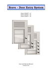
1.1.23
When using the PO reflector model, the 3 dB
contours of the computed component beams do not lie directly
on top of the beamlets.
An offset reflector produces beam squint perpendicular to the offset plane when excited with CP.
This is what you are observing. The algorithm SATSOFT uses to compute the feed locations
does not compensate for this. Thus, change the polarization to left hand, and the beams will
squint the opposite direction. Change to linear, and there is no beam squint. Also, the 3 db
contours will not lie exactly on top of the beamlets, because of the limitations of the placement
algorithm.
SATSOFT
2.00
-3
1.00
-3
-3
32.51
0.00
1
-1.00
-3
-3
-2.00
-2.00
8
-1.00
0.00
1.00
2.00
8
SATSOFT FAQ Version 2.3
www.satsoft.com
1.1.24
I have created an elliptical beam using the Gaussian
model. I can easily change the boresight by dragging the beam
around, but how can I rotate the beam about its axis?
In Antenna View, select Display | Boresight, and enter the boresight rotation in degrees into the
rotation field and click OK.
1.1.25
Shouldn't the contours look the same when the
Polarization field in Display | Contours is set to RSS or P1, if P1
is the copol component?
This is usually the case. However, if the antenna is circularly polarized, but was measured with a
linear source antenna (and vice-versa), P1 and P2 will be nearly equal in magnitude, and the
RSS will be 3 dB higher than either P1 or P2.
Another common problem occurs in ASCII pattern files when IUNIT=1, which means that the field
values should be specified in dB and degrees. Sometimes one of the field components is set to 0
dB when the field was really intended to be zero. If the component is really zero, it should be set
to -200 dB. Alternately, NCOMP could be set to 1, indicating a scalar pattern, and the component
omitted completely.
1.1.26
I want to generate a single circular beam with the
Physical-Optics Reflector Model. How should I set the parameter
"Beam Spacing" as there is only one beam? It seems to me that
the generated beam parameters, such as the peak gain, do
depend on the setting of "Beam Spacing.
Select the Focal Length radio button to manually specify the focal length of the antenna. Then,
increase the beam spacing until the directivity is maximized. This reduces the spillover loss. The
reason is that when the check box to the left of Feed Diameter is checked, that parameter is
computed automatically. Clear the checkbox if you wish to specify feed diameter manually.
Optimum aperture efficiency is obtained when the size of the feed is adjusted such that the
illumination at the edge of the reflector is about 10 dB down from that at the center. This produces
an aperture efficiency in the 72 to 75% range.
You may notice that rather low aperture efficiency is obtained at -3 dB crossover levels (when
Beam Spacing=Beamwidth), due to high spillover loss. However, the computed values reported
here are for a single component beam. When multiple beams are used, the feed-array factor
narrows the primary radiation pattern, reducing the edge illumination and the spillover loss. If only
a small number of beams is needed, increase their spacing to reduce the spillover loss.
Aperture efficiency is defined as antenna directivity divided by the quantity 4 pi A/lmbda**2 times
100%. This ratio is a figure of merit which compares the reflector's directivity to the directivity of a
uniformly illuminated aperture. This ratio includes the effect of feed spillover loss, but not ohmic
losses.
9
9
SATSOFT FAQ Version 2.3
www.satsoft.com
1.1.27
Is it possible to see a 1-D "cut" of a 2-D pattern using
SATSOFT? I have an antenna (theta, phi) plot and I want to see a
plot of the -10º<theta<10º cut for phi=0º. Is it feasible? If yes,
how?
SATSOFT does not have a pattern-cut plotting capability. This is on the wish list, however.
1.1.28
As far as I understand SATSOFT seems to be pretty
suitable for spacecraft reflector antenna design. Can it
successfully be used for design of satellite end user terminals
with a small dish antenna (diameter is less than 1m )? If yes,
would you give your guidelines. Can your software be compared
to TICRA's with respect to the above-mentioned problem
("Satellite End User Terminal" with a small Antenna)?
SATSOFT is oriented to spacecraft antenna design. However, you can turn off the maps, plot
patterns in (u,v) or angle space, and make the program look more like a general purpose antenna
program. SATSOFT/PO is certainly accurate for any type of reflector analysis. However, there
currently is no corrugated feed model, and you are limited to a single reflector (ie, you cannot
model a subreflector). There is no GTD option, which could be useful for far-out sidelobes and
back radiation. If you don't need this type of analysis, perhaps SATSOFT would work for you. We
are always looking for ways to improve our software to meet the needs of our customers. If there
are specific features that you require, please let us know.
Although there is some overlap in features, SATSOFT is complementary to Ticra's software.
Which is best for you depends upon your needs. You may find that SATSOFT is very useful even
if you already have the entire suite of Ticra's programs. If you are designing reflector antennas at
a satellite manufacturer, you will want to purchase GRASP. SATSOFT does not have as many
features as GRASP for defining reflector geometry. But you will find that SATSOFT is superb at
plotting GRASP patterns on maps of the earth, synthesizing shaped beams from component
beams sets computed with GRASP, defining synthesis station grids, coverage polygons, etc.
The SATSOFT/PO option is a vector reflector modeling program integrated into SATSOFT that
uses the physical optics method to predict the performance of the antenna. It is a very accurate
program but does not yet offer the flexibility that GRASP has for defining the reflector's geometry.
However, it is much easier to use. All of the inputs to the reflector model are accessed from the
Reflector Model Dialog.
SATSOFT has many of the tools you will need for spacecraft antenna design integrated into one
program. Antenna modeling, shaped pattern optimization, contour plotting, world maps and cities,
coverage polygon creation and analysis, performance tables, and many other features.
SATSOFT provides extensive context sensitive help making the program easier to learn how to
use.
SATSOFT/PRO adds the ability to shape multiple beams simultaneously, an invaluable feature if
you are creating constant flux beam sets. SATSOFT/PRO also has tools for pointing error
expansion of polygons, plotting of pointing error loci at polygon vertices, and conversion of
polygon viewpoint to multiple spacecraft locations.
If you are doing a lot of trade studies you can get them done very quickly with SATSOFT. Please
consult the online help for more information on SATSOFT and how to use it.
10
10
SATSOFT FAQ Version 2.3
www.satsoft.com
Reflector geometry can be written to a file in GRASP7 format by selecting File | Export Files |
Reflector Geometry. This facilitates comparison of antenna patterns computed with
SATSOFT/PO and GRASP7. Also, if you have not purchased SATSOFT/PO but have GRASP7,
this makes it easy to use GRASP7 with SATSOFT, since GRASP (u,v) pattern files can be
imported to SATSOFT when the antenna model is set to Pattern File. For more information on
exporting reflector geometry, please see Export Reflector Geometry Files.
Please click on Help | Help Topics after downloading and installing SATSOFT for an overview of
the software.
1.1.29
Is the SATSOFT earth model elliptical or spherical ?
As of v 2.2, a WGS84 ellipsoidal earth model is used.
1.1.30
Boresight is set for each antenna, but is it also
possible to set the satellite attitude (satellite depointing) with the
consequence of changing the antenna boresights?
No. However, S/C attitude is on the wishlist.
1.1.31
Is there documentation available that describes the
data format of the workspace file?
No. The SATSOFT work file is a Microsoft compound document file, which is essentially a file
system within a file. Many Windows programs use this type of file. However, the streams inside
the SATSOFT compound document are quite complex, and will change to accommodate new
features in the program.
1.1.32
What's the data format of the antenna pattern?
Please see the chapter "File Formats" in the online help system.
1.1.33
I have an ASCII antenna pattern file containing
E_theta and E_phi components. How do I import the pattern and
display the contours on an earth map?
Please see Help | Help Topics, and review the section Introducing SATSOFT. Briefly, the process
is as follows: Click on the New Satellite Toolbar Button to add a satellite, and then on the New
Antenna Button to add an antenna object. Double-click on the antenna object just created to
switch to the Antenna View for that object. Antenna pattern files can be imported from Antenna |
Properties. Contour levels are changed from Display | Contours.
1.1.34
How do you export pattern files to STK/COM?
From Antenna View, select File | Export Files | Pattern Files, select STK ASCII Directivity from the
File Format combo box. Note that STK currently only reads a single pattern from the file, so you
may wish to export only a single beam.
1.1.35
What is the best format for the radiation pattern files?
I suggest CPLAN type 20 ASCII, or type 520 binary pattern file format that is described in detail in
the File Import and Export section of the online help and printed docs. This format is used by
many spacecraft manufacturers to deliver antenna pattern data to their customers, and has
11
11
SATSOFT FAQ Version 2.3
www.satsoft.com
remained stable since it was first established in 1993. Thus, I am confident that you will find it to
be a suitable format for your data as well.
Please see UVGRID1.PAT, a sample pattern file installed to the Program files\satsoft\samples
directory.
1.1.36
I have two CPLAN ASCII (type 20) formatted files. The
pattern is identical in both files except that one of the files
contains two vector components, and the other only one. If I plot
the files in CPLAN, they overlay perfectly. However, if I plot both
with SATSOFT and overlay them, I get a 0.25 deg AZ offset. Have
you heard of anyone else having a similar problem when using
SATSOFT?
The beam center data on line 6 in your file is delimited with commas. CPLAN has no problem with
this, but SATSOFT v 2.06 reads the file incorrectly. This is also a problem with the frequency data
on line 7. This has been corrected in v 2.07 and later. Now, any of the values in the file can be
delimited with commas or spaces.
1.1.37
The data from our antenna measurements is not on a
regularly spaced grid. Can irregularly spaced antenna pattern
data be read by SATSOFT?
Yes, as of v 2.1, irregular grids are supported. Please see "SATSOFT Irregular Grid Pattern File
Format" under "File Import and Export."
1.1.38
The size of the .ssw work file seems to stay large
even after deleting the beams.
A new feature was added in v 2.1 to delete internally generated patterns from the file. Please see
"Reduce Workfile Size" under "Object Editing Views"
1.1.39
Only part of the diagram is shown in the "Print
Preview" function.
There is a known bug in the Print Preview feature - only part of the drawing is shown. However, it
is still useful to see how the plot will fit onto the printed page, so we have left this feature in. It
does not affect printing to the hardcopy device.
1.1.40
I cannot print out an antenna coverage over a NOVEL
network. What kind of trouble-shooting can I do? Can you give
me any suggestions and advice?
I do not know why you cannot print to a Novel network printer. Can you do so from other
Windows apps? So long as the printer has a working windows driver, SATSOFT should be able
to print to it. We do not have a Novel network, nor do we have access to one. We are running a
Windows network. Thus, we cannot be of much assistance in troubleshooting.
You might also try printing to a file, then copying that file to the network printer using copy file lpt1
/b
12
12
SATSOFT FAQ Version 2.3
www.satsoft.com
1.1.41
Do you have a means of converting the old CPLAN
.WRK files to the new SatSoft format? I have a client who has
sent me these old formatted files and I need to work with them in
SatSoft.
Select File | Open Workspace, or just drag the .wrk file from the Windows Explorer and drop it on
SATSOFT. Conversion is automatic.
1.1.42
When I try to import the attached CPLAN files (that
one of my clientscreated) I just get maps with no beams. Can
you help out? We are really trying to get the beams exported in
GXT format for use in ITU GIMS. I can no longer run CPLAN
because of Windows 2000.
SATSOFT only imports the main data block from a CPLAN workfile. It does not import the Beam
Designer data which is created in CPLAN when you select Tools | Beam Designer. Ask your
client to save the antenna pattern to a file using Beams | Files | Save Composite Beam or Save
Component Beams as the case may be. Then exit Beam Designer, and enter the filename of the
file just created in the Pattern File field of Display Contours. Have him provide the work file and
the pattern file to you. You will then be able to open the file in SATSOFT and view the contours.
1.1.43
Is there a shaped reflector model available for
SATSOFT?
No, we do not currently have a shaped reflector model for SATSOFT, but this is on the wish list.
1.1.44
When I start SATSOFT, no window appears, but there
is a SATSOFT button in the Windows quick-launch toolbar. Also,
Alt-F, etc, bring up SATSOFT menus, but again the GUI is not
visible.
The registry entries for SATSOFT have become corrupt. Select Start | Run, type "regedit,"
navigate to HKEY_CURRENT_USER | Software | Satellite Software, then delete the SATSOFT
key and all of its subkeys. Close regedit and restart SATSOFT.
1.1.45
pattern?
How do I invert the u axis when importing an antenna
Select Antenna | Model Properties when the "Pattern File" model is active, then click on Import.
The rotation matrix settings are at the bottom of the dialog box. This feature was added in v 2.1
Also, if you are importing a SATSOFT (CPLAN) type 20 pattern file, you can set IMAT to 2 in the
header. Please see "Antenna Pattern File Format" in the online help. \
13
13
SATSOFT FAQ Version 2.3
www.satsoft.com
1.1.46
I am trying to use Satsoft to create a synthesis station
file for POS. I have 10 stations and two frequency bands to
optimize directivity (Tx and Rx). I want to optimize at 3
frequencies in each band, for a total of 6 frequencies. The
directivity requirement varies from station to station, but is the
same for each of the 3 frequencies in the band. 3 of the stations
are not used to define the coverage in the Rx band. How do I
set the station type as "Exclude" in the Rx band for those 3
stations, but still have them as "Contour" for the Tx band?
When I set it to "Exclude", it excludes the station at all
frequencies, even though I've set the active layer to only the Rx
band.
Synthesis stations contain arrays of StationGoal objects for each composite beam and
polarization. The StationGoal objects have arrays of weights and db goals for each frequency, but
the Exclude property is scalar, that is, is not stored for each frequency. However, you could set
Rel Weight to zero for the frequencies you would like to exclude. POS will then ignore the station.
1.1.47
How can I digitize contours for export to STK?
Follow the instructions in the help file to digitize the contours. There is a tutorial video on this
subject at http://www.satsoft.com/downloads/tutorial5.wmv Export the contours as a GXT file (File
| Export Files | ITU GXT File). This can be imported with STK/COMM.
1.1.48
SATSOFT caused an exception 10h in module
satsoft.exe under Windows 95 or Windows 98
This problem may occur when the following conditions are true:
Your computer's operating system is Microsoft Windows 95 or Microsoft Windows 98.
You have a Hewlett-Packard or HP-compatible printer that uses the Hewlett-Packard PCL printer
language.
The printer uses a printer driver supplied by Hewlett-Packard or another third-party, rather than
the driver that is included with Microsoft Windows.
This problem occurs because some third-party PCL printer drivers are incompatible with
SATSOFT. The problem is more likely to occur when the PCL printer is set as your default printer,
but may occur any time you use the printer with SATSOFT.
See Microsoft KB Q273860. This can occur when opening a workfile or adding objects to the
satellite tree. SATSOFT accesses the printer driver to determine the page size and other
properties.
To see if the printer driver is causing the problem, change the default printer to a different printer
and see if the problem still occurs.
Delete and then reinstall the printer driver from the Microsoft Windows CD to rectify the problem.
14
14
SATSOFT FAQ Version 2.3
www.satsoft.com
1.1.49
I am using Satsoft to verify ITU sidelobe and crosspol requirements for a satellite antenna I'm designing. In order
to do this, I need to project onto the map a set of concentric
ellipses. The ellipses are defined by a center point in AZ/EL,
major/minor axes defined as angles subtended from the satellite,
and a tilt angle w.r.t. the equator. I need to plot these on top of
my antenna patterns and make assessments. Can you suggest
a way to do this?
Add an antenna object for each ellipse in the Satellite Tree. In each, create a Gaussian beam
with the proper major and minor axes. Use boresight rotation to achieve the proper tilt. Then plot
only the 3 db contour.
All of the beams will be visible in composite view, as well as the antenna pattern that you are
designing.
1.1.50
When Map Rotation is checked (Display | Maps) In
Antenna View, antenna boresight is always at (0,0). This rotates
the polygon (and map) through the inverse of the boresight
angles. How can I obtain the coordinates of the rotated polygon?
In v 2.1 and later, copy the polygon object to a new one directly beneath the satellite - click and
drag the polygon object in the Satellite Tree with the cntrl key pressed, and drop directly onto the
satellite object.
In v 2.07 and prior, switch to the Polygon View containing the polygon. Export the polygon to a
file. Create a new polygon object beneath the satellite object and then import the polygon.
Double-click on the new polygon object, and select Polygon | Contour to change it to a contour
type object. Select Display | Boresight and set the boresight angles to the same values as in the
Antenna View. Select Polygon | Coverage to change back to a coverage type polygon, then
Display | Maps and change to Equirectangular projection. Then select Polygon | Contour. All
polygon points will be rotated thru the inverse boresight angles and converted to (u,v).
1.1.51
I always use the equation that antenna -3 dB
beamwidth = 70*lambda/D. This would lead to a 6 meter
antenna at 12 GHz giving a 0.3 degree beamwidth. However,
when I run Satsoft with the analytic reflector model with a 6
meter at 12 GHz I get a beamwidth of 0.25. Why is this?
A more accurate approximation is
beamwidth = 1.029f*(1.0 - 0.212*log10(edgil))/refdial;
With .7 for the edge illumination edgil, this works out to 60.8/refdial. This is the approximation
that SATSOFT uses in the reflector dialog. The actual pattern computations are more rigorous.
The PO reflector model is the real proof, but the analytic model you are using is very close to the
PO model for these canonical cases.
In short, use 60.8/refdial for back of the envelope calculations.
15
15
SATSOFT FAQ Version 2.3
www.satsoft.com
1.1.52
How do I convert polygons contained in a coverage
polygon file (*.cov) to a map database file compatible with
SATSOFT
Just drag and drop the .cov file onto a polygon view, select the polygons you wish to export, then
Select File | Export Polygons, select "Map Database (*.dat)" as type, and call the file
wmap4.dat. Then move this file to your SATSOFT directory (rename the existing wmap4.dat to
something else) and restart SATSOFT.
1.1.53
Is there a way to have multiple maps with different
projections?
In Composite View, select Display | Maps, clear the "copy map and city settings to child objects"
checkbox. Then you can select different map projections in different views from Display | Maps.
1.1.54
How do I move the satellite without having the
station grid move also.
You can't. The station grid is fixed to the antenna, since it is used to define the shape of the
antenna pattern. However, if the stations are located on the earth, you can easily create a city
table matching the locations of the stations. Cities are fixed to the earth and do not move with the
satellite or antenna. Here is the procedure:
Add the desired synthesis stations in Antenna View
Select Tools | Performance Table
Select Tools | Options (in Performance Table View), make sure the following boxes are checked:
Country, City, Desig, Lon, Lat. Under "Record Type" check "Synthesis Stations" but clear "Cities"
checkboxes. Under "Beam Type" check either component or composite as appropriate. Then
click OK.
In the performance table grid, click in the first cell in the "Country" column, then drag the mouse
to the last row in the "Lat" column and press cntrl-c to copy the highlighted cells to the clipboard.
Go back to Antenna View, select Display | Maps, click on the "Cities" tab, click on "Add City",
select the cell underneath "Country" and press cntrl-v to paste the copied cells. This adds the
latitude and longitude of each station to the city table.
1.1.55
Does moving the boresight cause the feeds to move
appropriately?
Changing the boresight rotates the entire antenna. It does not change the positions of the feeds
in the coordinate system of the antenna.
To change the positions of the feeds, move the corresponding beamlets by first highlighting those
you wish to move. Then click on the move beamlet toolbar button and click and drag the
beamlets with the mouse.
16
16
SATSOFT FAQ Version 2.3
1.1.56
map(s)?
www.satsoft.com
How do I make the polygon not appear on the
Double-click on the polygon object in the Satellite Tree that is beneath the antenna object you
are working with. This opens a Polygon View for that object. Highlight the polygon(s), select
Properties, then clear the "Show in Parent View" checkbox.
1.1.57
How do I change the contour labels to show EIRP for
an imported GXT pattern?
Is there any way that I can plot EIRP contour levels, instead of the gain contour values (e.g., 53
dBW vs. -2 dBi) for an imported GXT file?
It is easy to compute and display absolute EIRP contours for a pattern grid. However, since GXT
files actually contain polygons rather than a grid of gain values, the only thing you can do is edit
the polygon labels. Thus, in Polygon View, you would select all of the -2 dB contours, click on the
Properties toolbar button, check the Label box, enter 53 and click OK.
To quickly deselect all selected contours, click on Delete and then immediately on Restore.
Repeat the procedure for the rest of the contours.
Note also that the polygon object should be a child of a Satellite rather than Antenna object.
Then, when you drag and drop the gxt file onto the view of the polygon object, the polygons will
automatically be drawn as contours rather than coverages, ie, the labels will be embedded in the
contours, and the contours will be drawn in color.
1.1.58
I exported the antenna pattern I created, but when I
show it in STK, the contours aren't as smooth as I'd like.
I think it is due to the interpolation of the pattern file. Is there a way for me to export more points
in the Composite beam? Essentially, I'd like to get the .pat file to be bigger, with more detail.
From Antenna | Beamlet & Station Grids, increase the resolution field from the default of 2 to say,
5 or 10. Then recompute the pattern & export it. With higher resolution, you won’t need whittaker
interpolation when contouring, so select Display | Contours, and set the whittaker field to 1.
1.1.59
How are polygons used?
Polygons have many uses in SATSOFT. They can be used to define coverage areas, for which
automated pattern synthesis can then be used to create antenna designs. Polygons also can
hold antenna contours; either imported from gxt files, or from digitized antenna pattern plots.
Please do a search on "polygon" in the online help. Also, see the tutorial videos on the SATSOFT
cd.
1.1.60
What is the best way to determine the centroid of a
polygon in satellite coordinates?
Import the polygons to a Polygon View. If the polygons are defined in geographic coordinates (lat,
lon), then change the map projection to satellite coordinates (e.g., az/el), which converts the
coordinates of all polygons in the view. This conversion depends upon the satellite position, so it
is important to set this first.
17
17
SATSOFT FAQ Version 2.3
www.satsoft.com
After conversion, select all the polygons (use the toolbar button "Invert Selected State"), then
click on the Analyze toolbar button. The centroids of each of the polygons will be listed in the log
window.
1.1.61
How do specify the coordinate system of a pattern
file, when exporting or importing in GRASP format?
When you export the pattern, from File | Export Files | Pattern File, select "GRASP ASCII." The
pattern is always written in (u,v) coordinates. There is no way to change this. When importing
files, the coordinate system of the pattern is read automatically from the file header. Please see
"GRASP Pattern Files" in the File Import and Export chapter of the online help.
1.1.62
We are having problems with installing SATSOFT.
After we select workstation install, accept the license agreement, enter user information and
select typical installation, a dialog box with the following message appears: "Please insert
SATSOFT CD-ROM to continue." The installation will not proceed past this point. Are we
missing files from the CD?
Probably not. Clean out your Windows temp directories. The location of these is OS dependent.
On W2000, it might be something like "D:\WINNT\profiles\username.JANUS\Local
Settings\Temp" Note that when you run setup.exe from the CD, the install files are unpacked and
placed into your temp directory. Old versions of these can cause the problem you are having.
1.1.63
When using the analytic phased array model, the
directivity of the main beam does not change even if I increase
the element spacing enough to bring grating lobes into real
space.
The directivity of the analytic array model is only accurate when the radiators are closely spaced
enough to avoid grating lobes. Note that increasing the element spacing generally implies a larger
element size, which produces a narrower pattern that helps to filter out grating lobes. To simulate
r
this effect, enter a value for the element factor cos to achieve particular 3 dB beamwidth. Use
r=
− 0 .3
log(cos(0.5θ 3 )) , where θ 3 is the desired 3 dB beamwidth of the element pattern. This is
approximately the reciprocal of the radiator spacing in wavelengths. For example, a 3.5λ element
will produce a beamwidth of 16.4°.
1.1.64
When I try to paste an antenna object from the
clipboard, I get the error message, Failed to create stream xxxxx,
STG_E_INVALIDNAME
SATSOFT stores imported antenna pattern files in a stream inside the workfile. When an antenna
object is copied to the clipboard, any pattern streams that it refers to are copied to the clipboard
as well. When the object is subsequently pasted back into satsoft, a new stream is created to
store the pattern. This new stream is created with the same name. However, if you are pasting
back into the same workfile, there is a name collision. In this case, satsoft appends the filename
with an integer in order to create a uniquely named stream. However, if the original stream name
was 31 characters long, the new name will be 32 characters long, which exceeds the maximum
for streams, producing this error message.
18
18
SATSOFT FAQ Version 2.3
www.satsoft.com
To avoid this problem, if the object is to be copied back to the same instance of satsoft, copy the
file by holding down the Ctrl key and dragging the antenna object to the new location in the
satellite tree. Copying an object this way is faster and does not use the clipboard at all. It also
does not bloat the workfile by making unnecessary copies of antenna patterns.
Keep pattern file names to 30 characters or fewer.
1.1.65
I need to draw a composite of several satellites in
composite view. However, in the equirectangular projection,
SATSOFT truncates the map. How can I draw the map beyond
this point?
SATSOFT won't plot more than 360 deg of map in the equirectangular projection. The map
central longitude is set in Display | Maps. By default, this is locked to the position of the first
satellite, which may not always be appropriate, especially when there is more than one satellite
position. From Composite View, select Display | Maps and set the map longitude to whatever the
center of the map should be. SATSOFT will display the map 180 degrees on either side of the
central longitude.
19
19